JPX Battery Pack User Guide 3
Introduction
Welcome to the JPX Battery Pack User Guide—a comprehensive resource designed to
empoweryouwiththeknowledgeandcondencetomakethemostofyourportable
power solution.
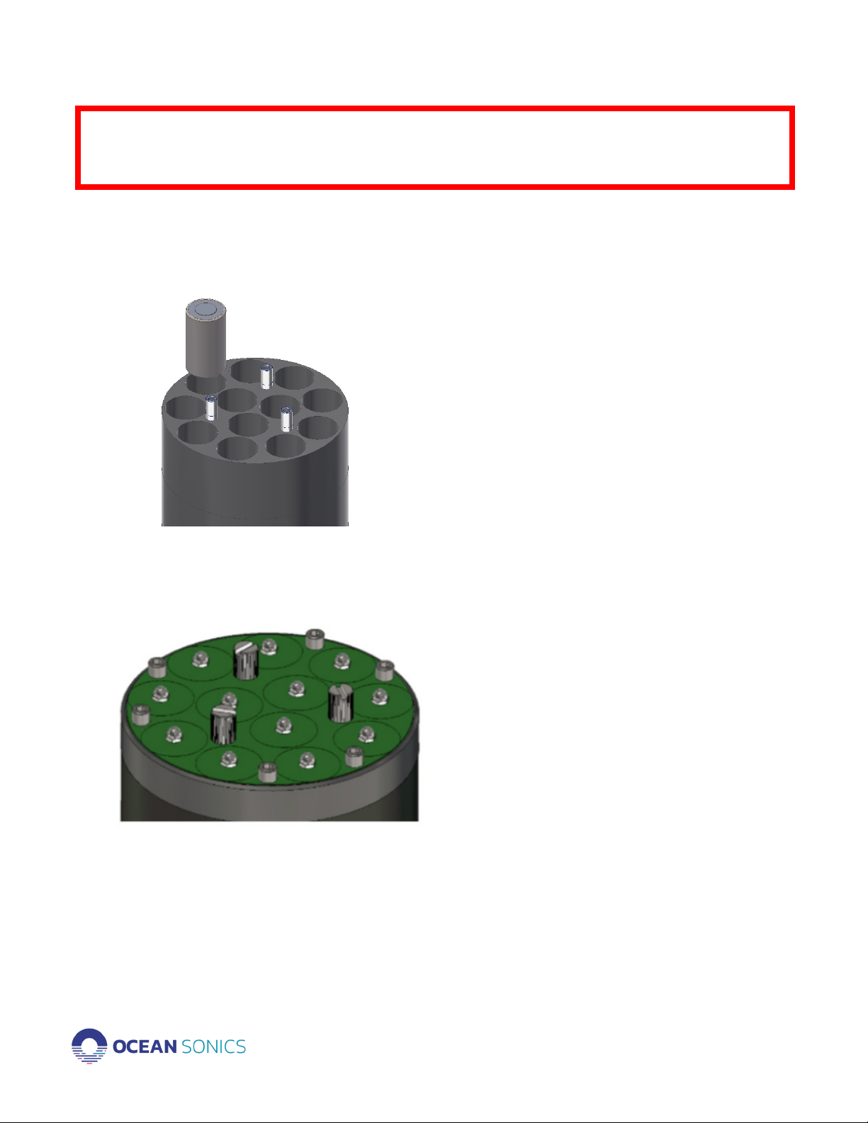
The Ocean Sonics JPX Battery Pack is a submersible unit that provides additional power
to one or more hydrophones for long-term deployments. The pack uses a maximum of 72
D-cellbatteriesthatareeld-changeableandcanprovidepowerforonehydrophonefor
30-90days*.Allbatterypacksaremadeoflightweightglassbercompositecase.There
are 3 types of end cap materials for varying depth ratings for 200m (Engineered Plastic),
900m (Anodized Aluminum) and 3500m (Titanium).
In this guide, you will be provided with a breakdown of the essential features,
functionalities, and safety measures that our battery pack offers. Whether you’re a
seasoned hydrophone and battery pack user, or new to Ocean Sonics equipment this guide
is tailored to meet your needs. We understand that in a world increasingly dependent on
technology, a dependable and well-understood power source is paramount. With clear
instructions, insightful tips, and a focus on safety, this Battery Pack User Guide aims to
enhance your experience, extend the life of your hydrophones, and ensure your interactions
withourproductareasefcientandenjoyableaspossible.So,let’sdelveintotheworldof
portable power and unlock the full potential of your battery pack.
*Varies depending on differing brands of batteries / Value based on typical cells
Safety
1. Always open pressurized vessels with additional care
2. After use in water, ensure battery pack unit is dry before opening
3. After use in water, ensure users hands are dry when securing contact plate
4. Always use PPE safety gear when working with electrical equipment
5. Please follow all safety and danger guidelines of personally purchased batteries
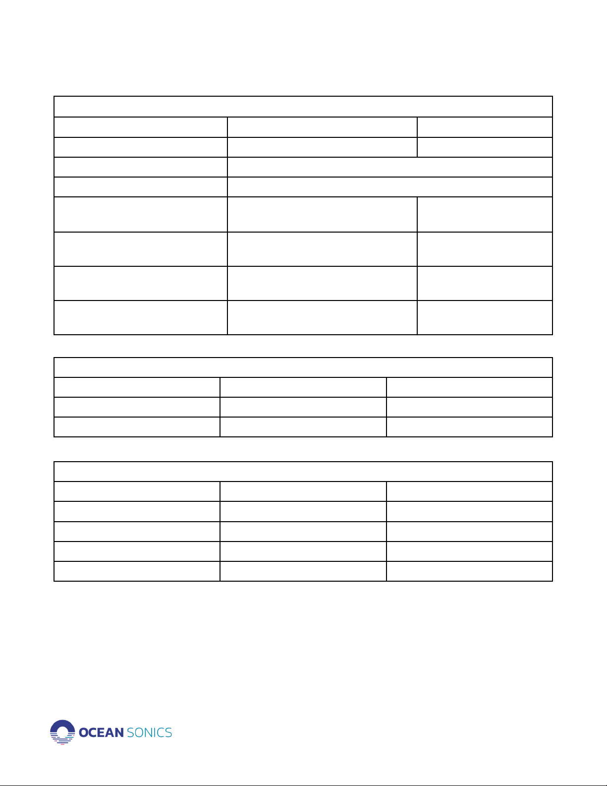
Included tools and spare parts
JP2-BX
1. Included Tools/Spares
2. 1 x 4mm Hex Key
3. 2 x 02-255 O-Rings
4. 10mL Molykote 44 Grease
5. 2 x M8x50 Soft Point Set Screws
JP9-BX
1. Included Tools/Spares
2. 1 x 4mm Hex Key
3. 1 x 3mm Hex Key
4. 2 x Can Anode
5. 1 x Endcap Anode
6. 2 x 02-255 O-Rings
7. 10mL Molykote 44 Grease
8. 2 x M8x50 Soft Point Set Screws