Ogden BCH610 User manual

M
Mo
od
de
el
l
B
BC
CH
H6
61
10
0
M
MO
OW
WE
ER
R
C
CA
AR
RR
RI
IE
ER
R
I
In
ns
st
tr
ru
uc
ct
ti
io
on
n
M
Ma
an
nu
ua
al
l
a
an
nd
d
P
Pa
ar
rt
ts
s
L
Li
is
st
t
Use this Manual for Safety Instructions and Operating Instructions.
Make sure everyone who operates this machine has read the manual completely.
Save for future reference.
I
IM
MP
PO
OR
RT
TA
AN
NT
T:
:The Mower Carrier is designed to operate with Disc Mowers up to
10 ½’ in size. In order to insure safe operation it may be necessary to install the
optional Weight Box for additional counter balance.
W
WA
AR
RN
NI
IN
NG
G:
:DO NOT DISCONNECT MOWER CARRIER FROM
TRACTOR UNLESS MOWER CUTTERBAR IS LOWERED TO THE
GROUND
O
Og
gd
de
en
n
M
Me
et
ta
al
lw
wo
or
rk
ks
s
I
In
nc
c.
.
301 N. Marilyn Ave.
PO Box 128
Ogden, IL 61859
217-582-2552
Fax 217-582-2746
email: ogdenmetalworks@ogdenmetalworks.com
www.ogdenmetalworks.com
5-19


1
Mower Carrier
Table of Contents
Page 2 Introduction
Page 3 Safety
Page 4 Decals
Page 5 Assembly Instructions
Page 8 Attaching Mower
Page 9 Operation
Page 10 Transport
Page 11 Maintenance
Page 12 Mower Carrier Parts List
Page 15 Warranty Card

2
I
In
nt
tr
ro
od
du
uc
ct
ti
io
on
n
It is important that you thoroughly understand the operation of the Mower Carrier before
use. Read through this manual completely, watching especially for safety symbols (see
illustration below). This safety alert symbol is used throughout this manual to identify
possible safety hazards.
It is the user’s responsibility to read the operator’s manual and comply with all the
instructions pertaining to operation and maintenance. It is also the user’s responsibility to
inspect the machine at regular intervals and repair or replace worn or damaged parts
when continued use would cause damage or excessive wear to other parts.
The manufacturer reserves the right to make improvements, discontinue or change
specifications, models or design without notice and without incurring obligation.
When ordering parts for your Mower Carrier, please specify the part number and the part
description as shown in the parts listing in this manual. Please give the serial number of
the Disc Mower Carrier in all correspondence when referring to the Disc Mower Carrier.
Record the serial number and purchase date here for future use.
Serial Number ________________________
Model __________________ Purchase date___________________________
IMPORTANT: When this machine is traded or sold, make sure this manual
accompanies the machine so future operators will have complete operating instructions
and safety warnings available to them.

3
S
Sa
af
fe
et
ty
y
I
In
ns
st
tr
ru
uc
ct
ti
io
on
ns
s
CAUTION: This machine should never be operated
by anyone who is not familiar with the product and
has not read the instruction manual. Do not allow
children to operate the Mower Carrier.
All persons operating this machine
should read and understand the
Instruction Manual.
Read and understand all safety decals
located on the machine.
Keep Safety Decals clean and legible at
all times.
Replace Safety Decals that are missing
or become illegible.
Do not allow anyone to ride on the
machine.
Be sure machine is attached securely to
the tractor before operating or
transporting.
Inspect the Mower Carrier daily.
Lubricate and repair or replace parts as
needed.
Maintain and keep all Safety Shields in
place.
Before operating the machine inspect for
loose or damaged bolts or parts and
make necessary repairs before starting.
All bystanders should be a safe distance
from the machine when in operation.
High-pressure oil leaks can penetrate
skin causing serious injury. Do not use
your finger or other skin to check for
leaks.
Disengage PTO, apply parking brake
and stop tractor engine before
dismounting tractor.
Keep hands, feet and clothing away from
moving parts.
Never transport faster than surface
conditions allow.
Display the SMV Emblem when
transporting with a tractor.
Make sure you are in compliance with
all local regulations regarding
transporting agriculture equipment on
public roads and highways. Consult
your local law enforcement agency for
further details.
Ensure that the Slow Moving Emblem
(SMV) and all reflectors and lights
required by the local highway and
transport authorities are in place and are
clean and visible by overtaking and
oncoming traffic.
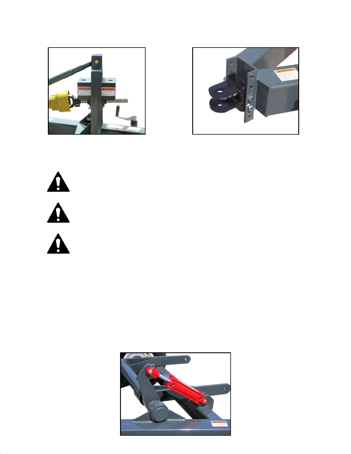
Be sure the Drivelines are properly
connected and that any quick
disconnects are locked before operation.
Do not disconnect Disc Mower Carrier
from tractor unless cutterbar is lowered
all the way to the ground.

4
D
De
ec
ca
al
ls
s
Important: Many of the following Decals are located on your Disc Mower Carrier.
Before you operate the Disc Mower Carrier, read and understand the purpose for each
Decal. Replace any damaged Decals. Keep all Decals clear and readable.

5
B
BC
CH
H6
61
10
0
M
Mo
ow
we
er
r
C
Ca
ar
rr
ri
ie
er
r
A
As
ss
se
em
mb
bl
ly
y
I
In
ns
st
tr
ru
uc
ct
ti
io
on
ns
s
CAUTION: Wear proper protective equipment such as Safety
Glasses and protective shoes when assembling.
Lay out all parts so location and verification will be easier. Make sure all parts were received
before proceeding with the assembly.
Install the two Tire and Wheel Assemblies onto the Hub Assemblies and properly tighten Lug
Bolts or Lug Nuts.
Attach the Tongue Jack to the Main Frame Weldment and secure in place with the Locking Pin.
Attach the Driveshaft Support Weldment to the Main Frame using six 1/2” x 1 ½”” Capscrews,
Lockwashers and Hex Nuts. If the Spline Shaft and Flange Bearings are not installed in the
Driveshaft Support, do so at this time using four ½” x 4 1/2” Hex Capscrews, Lockwashers and
Hex Nuts. Mount the Flange Bearings with the Grease Zerks toward the bottom. Install the
Spline Shaft with 5” of shaft between the bearing flange and the end of the shaft protruding on
the backside. After inserting the Spline Shaft into the Flange Bearings, be sure to lock the
eccentric lock collars on both Flange Bearings. Standing at the rear of the Mower Carrier and
facing forward, lock both collars in a clockwise direction and tighten the setcrews.
Install the two Driveline Shields using eight 3/8” x 1” Hex Capscrews, Lockwashers and Hex
Nuts.

6
Attach the Top Link using Pin and Hairpin.
Attach the Tongue Clevis using two 5/8” x 6” Capscrews and Nylock Nuts.
WARNING:Always wear protective eye goggles and use a magnifying
Glass or hold a piece of wood on suspected leaks. Pinhole hydraulic leaks
can penetrate skin. Do not touch.
CAUTION: Make sure a restrictor is installed in one of the hydraulic lines.
Failure to use a restrictor will allow the machine to raise and lower rapidly
and could result in damage to the machine and injury to bystanders.
CAUTION: Operate the cylinder through the cycle a few times to
expel air from the system. Failure to fully charge the hydraulic system
could result in injury when the mower falls abruptly.
Mount the Hydraulic Cylinder on the Carrier and install two ½” NPT Male x 3/8” JIC Male
Elbows in the Hydraulic Cylinder. Note: Do not use Teflon tape, only use liquid type thread
sealant. Attach the 114” Hose with ½” NPT Male - 3/8” JIC Swivel ends to the front port of the
Hydraulic Cylinder. Attach the 122” Hose with ½” NPT Male – 3/8” JIC Swivel ends to the rear
port of the Hydraulic Cylinder. Install the Restrictor on one of the Hydraulic Hoses before
installing a Hydraulic Coupler. Route the Hydraulic Hoses through the loop on the side of Drive
Shaft Support Weldment and then to the tractor. Before attaching a Mower to the Mower Carrier
operate the Hydraulic Cylinder several times to purge the air out of the system to prevent any
sudden drop.
A
AT
TT
TA
AC
CH
HI
IN
NG
G
M
MO
OW
WE
ER
R

7
CAUTION: The Mower Carrier is designed to operate with Disc
Mowers up to 10’ 6” in size. However in order to insure safe
operation it may be necessary to install the optional Weight Box for
additional counter balance.
T
Tr
ra
ac
ct
to
or
r
D
Dr
ra
aw
wb
ba
ar
r
a
an
nd
d
A
Ad
dj
ju
us
st
ta
ab
bl
le
e
C
Cl
le
ev
vi
is
s
H
Hi
it
tc
ch
h
Before attaching the Mower Carrier to a Tractor, it is very important to adjust the Tractor
Drawbar and Clevis Hitch on the Mower Carrier. The Mower Carrier is designed to operate with
a 540-RPM PTO Drive. The Tractor Drawbar must be set at the standard distance for 540-RPM
PTO Drives which is 14 inches from the end of the PTO Shaft on the Tractor to the Hitch Pin
hole. The Tractor Drawbar can be adjusted to obtain this measurement. The Clevis Hitch on the
Mower Carrier is designed to provide four different height positions. Select the proper position
to keep the Main Frame and Mower Carrier parallel with the ground. After the Tractor Drawbar
and the Mower Carrier Clevis Hitch are properly adjusted, the Tractor and Mower Carrier can be
hitched together.
WARNING: Do not disconnect Mower Carrier from Tractor
unless Cutterbar is lowered to the ground.
D
Dr
ri
iv
ve
el
li
in
ne
e
When attaching a Mower to the Mower Carrier, the original Mower Driveline will be used
between the Tractor and the input on the Mower Carrier. Due to variations in the length of PTO
Drivelines it may be necessary to shorten the Mower Driveline to fit between the Mower and the
input on the Mower Carrier. Consult your Mower’s Operating Manual for proper cutting
procedure. Be sure to allow a 1” safety margin at the Driveline’s closest collapsed length. Do
not shorten more than necessary. The Driveline halves should have an overlap of 4” to 6” after
shortening. The PTO Driveline that was furnished with the Mower Carrier will connect from the
Mower Carrier to the Mower.
CAUTION: PTO Drivelines must not bottom out or Damage will
occur.
CAUTION: Grease Drivelines Daily. Failure to do so may cause
severe damage.

8
CAUTION: When attaching the PTO Driveline make sure the yoke is
properly locked on the shaft.
Always have the Mower in the working position when attaching to the Mower Carrier and
always have the Mower Carrier attached to a Tractor.
Attach the Mower to the lift arms on the Mower Carrier. Be sure to install and tighten the 3/4” x
6 ½” Hex Capscrew and ¾” Nylock Nut.
Attach the Top Link between the Mower and Mower Carrier. To adjust the Mower angle, screw
the Top Link in or out. Consult the Mower Operator’s Manual for the most efficient angle.
Lengthen any Mower Locking Mechanism cords so they reach the tractor cab.
B
Be
ef
fo
or
re
e
O
Op
pe
er
ra
at
ti
in
ng
g
Attach the Mower PTO Driveline between the Tractor and Mower Carrier.
Attach the PTO Driveline that came with the Mower Carrier between the Mower Carrier and the
Mower.
CAUTION: When attaching the PTO Driveline make sure that the
Yoke is properly locked on the shaft.
WARNING: Operate only with 540 RPM PTO
Connect the Hydraulic Hoses for the Mower Carrier to the Tractor.
Connect the Hydraulic Hose for the Mower to the tractor.
Start the Tractor and engage the Hydraulics to check for proper operation.
CAUTION: Always attach the Mower Carrier to a Tractor before
folding or unfolding the Cutter Bar. Failure to do so could result
in damage to the implement and or possible personal injury.

9
Make sure all Bolts and Nuts are tight. Recheck after a few hours of operation.
Check Tires and inflate to proper pressure.
Grease Drivelines, Bearings and Grease Zerks on Pivot Assembly.
O
Op
pt
ti
io
on
na
al
l
W
We
ei
ig
gh
ht
t
B
Bo
ox
x
To insure safe operation with heavy or larger Disc Mowers a bolt-on Weight Box is available to
add counter balance. It may be necessary to install this Weight Box for additional counter
balance when using a large or heavy Disc Mower.
CAUTION: Do not operate the Mower Carrier without sufficient
counter balance to prevent a rollover.
O
Op
pe
er
ra
at
ti
io
on
n
O
Op
pe
er
ra
at
ti
in
ng
g
I
In
ns
st
tr
ru
uc
ct
ti
io
on
ns
s
The PTO Operating Speed for the Mower Carrier is 540 RPM. Do not over speed.
Many factors can determine the proper ground speed such as ground conditions, density,
humidity and type of forage to be cut. Consult the Mower Operator’s Manual for determining
the proper ground speed.
Always operate the Mower Carrier in a safe manner.
DANGER: Never allow children to operate, ride on or come close
to the Mower Carrier and Tractor while in operation.

10
T
Tr
ra
an
ns
sp
po
or
rt
t
Make sure you are in compliance with all local regulations regarding the transporting of
agriculture equipment on public roads and highways. Consult your local law enforcement
agency for further details.
Ensure that the Slow Moving Emblem (SMV) and all reflectors and lights required by the local
highway and transport authorities are in place and are clean and visible by overtaking and
oncoming traffic.
When transporting the Mower Carrier, with a Mower attached, be aware that on the right side of
the Tractor the Mower may extend beyond the Tractor tires.
Make sure the Cutter Bar is locked and secured for transporting.
WARNING: Always use the Tractor Warning Lights, SMV
Emblem and Reflectors for adequate warning to operators of other
vehicles.
M
Ma
ai
in
nt
te
en
na
an
nc
ce
e
Grease all Drivelines, Bearings and Grease Zerks daily to ensure proper operation.
Periodically check all Bolts and Nuts for tightness.
Periodically check Tire pressure and inflate to recommended pressure.
Check Hydraulic Hoses periodically for cracks, abrasions or leaks. Replace defective hose
immediately.
Repack wheel bearings every six months.
Caution: Never make adjustments or perform maintenance while
the Tractor is running. Allow all mechanisms to fully stop before
cleaning, adjusting, or doing maintenance.

11
Notes

12

13
BCH610 Parts List
Item No.
Part No.
Description
Qty.
1
BCH102
Tongue Clevis
1
2
BCH107
Drive Shaft Support Weldment
1
3
BCH100
Main Frame Weldment
1
4
MC109
Flange Bearing, 1 3/8”
2
5
MC138
Bearing Spacer *See note below
1
6
MC108L
Spline Shaft
1
7
BCH111
Driveline Shield
2
8
BCH112
Top Link
1
9
K-202
Top Link Pin
1
10
K-232
Hairpin
1
11
0-51
Tongue Jack
1
12
K-211
Hydraulic Cylinder, 3” x 8”
1
13
MC133
Cylinder Pin
2
14
MC134
Clip Pin
2
15
BCH114
Hydraulic Hose, ½” MP x 3/8” JIC, 122”
1
16
BCH115
Hydraulic Hose, ½”MP x 3/8” JIC, 114”
1
17
BCH123
Hydraulic Hose, ½” MP x ½” MP, 122”
1
18
MC122
Elbow, 3/8” JIC M x ½” MP
2
19
OE-302
Pipe Coupler, ½” Female
1
20
0-57
Flow Restrictor, ½” NPT, 1/32”
1
21
MC124
Grease Seal
1
22
MC125
Inner Bearing
2
23
MC126
Wheel Hub
2
24
MC127
Outer Bearing
2
25
MC128
Flatwasher
2
26
MC129
Castle Nut
2
27
MC130
Cotter Pin
2
28
MC131
Hub Cap
2
29
MC135
Lug Bolt
12
30
MC103
Tire & Wheel Assembly
2
31
0-157
Hex Capscrew, 3/8” x 1 ½” GR5
2
32
MCH38F
Flatwasher, 3/8”
4
33
NL38
Nylock Nut, 3/8”
2
34
0-172
Hex Capscrew, ½” x 1 ½” GR5
6
35
H12-412
Hex Capscrew, ½” x 4 1/2” GR5
4
36
0-173
Lockwasher, ½”
10
37
0-153
Hex Nut, ½”
10
38
BCH587
Hex Capscrew, 5/8” x 7” GR5
2
39
MCH580
Nylock Nut, 5/8”
2
40
BCH3465
Hex Capscrew, ¾” x 6 ½” GR8
1
41
0-170
Hex Nut, ¾”
1
42
K-324
Lockwasher, ¾”
1
Not shown
MC110
Drive Shaft
1
*After serial #8004 Bearing Spacer was welded to Drive Shaft Support Weldment

14
Notes

15
Warranty Policy
Ogden Metalworks, Inc. warrants this product to be free from defects in material and or workmanship
under normal use and service, when set up and operated as intended and under normal service and
conditions and in accordance with the instruction manual, for one year from the date of delivery by the
dealer to the original purchaser. Ogden Metalworks, Inc.’s obligation under this warranty is limited to the
replacement of any part or parts which are determined defective by Ogden Metalworks, Inc. due to
factory workmanship and or material. This warranty does not cover common wear items. Credit for
required labor will be issued at the company’s discretion.
This warranty is void on any unit which has been modified or which has been subject to misuse,
negligence or accident. Ogden Metalworks, Inc., reserves the right to request the return of any part in
question to be sent to the factory for inspection. All returned parts must be sent to the factory freight
prepaid.
This warranty is extended solely to the original purchaser and is not transferable. This warranty is not
valid unless the warranty card has been returned to Ogden Metalworks, Inc. within 30 days from the date
of purchase by the end user. O
Og
gd
de
en
n
M
Me
et
ta
al
lw
wo
or
rk
ks
s,
,
I
In
nc
c.
.
Ogden Metalworks, Inc. reserves the right to change
specifications and dimensions without notice.
WARRANTY CARD
Ogden BCH610 Mower Carrier
Please Print Date Purchased ______________
Name __________________________________________Phone #__________________
Address __________________________________________________________________
Serial No. _________________ Model No. _________________________
Dealer Purchased From: ____________________________________________________
Address __________________________________________________________________


Other Ogden Farm Equipment manuals
Popular Farm Equipment manuals by other brands

Gronomics
Gronomics CCPC 45-45 Assembly instruction

KUHN
KUHN HRB 122 Operator's manual

Digga
Digga DOZER BLADE Operator's & parts manual

Dion-Ag
Dion-Ag Scorpion 300 Setup / PDI Guide

Titan Attachments
Titan Attachments ROTIL48 Operator's manual

Big Dutchman
Big Dutchman Dry Rapid DR 1500 Mounting and operating instructions