OHAUS Defender i-DT61PW User manual

Defender 6000 Indicators
Instruction Manual
5 Commonwealth Ave
Woburn, MA 01801
Phone 781-665-1400
Toll Free 1-800-517-8431
Visit us at www.TestEquipmentDepot.com


Defender 6000 Indicators EN-1
Table of Contents
1. INTRODUCTION ................................................................................................................................................3
1.1. SAFETY PRECAUTIONS ................................................................................................................................................... 3
1.2. INTENDED USE ............................................................................................................................................................ 3
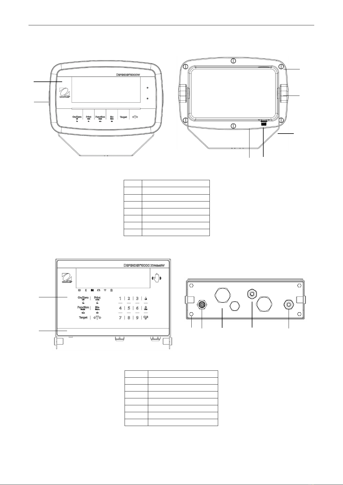
1.3. OVERVIEW OF PARTS AND CONTROLS .............................................................................................................................. 4
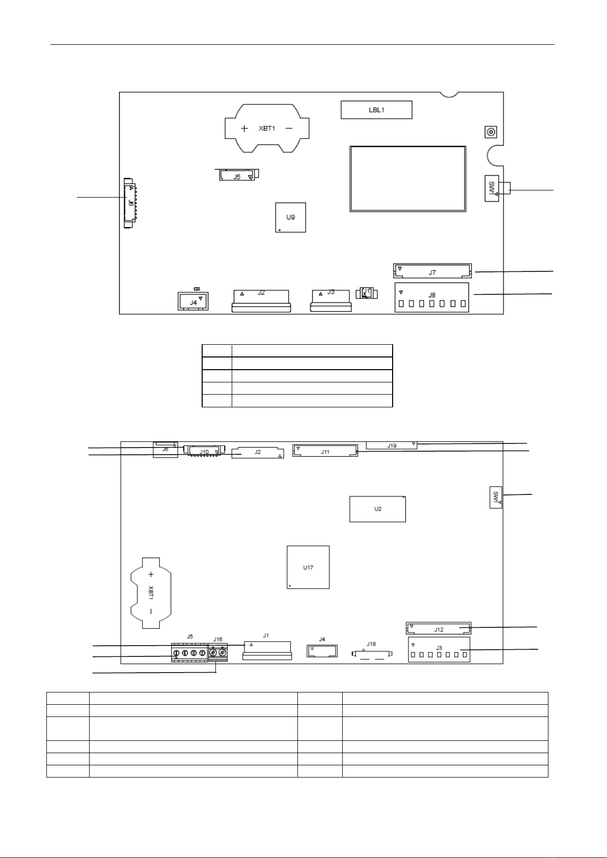
1.4. MAINBOARD ............................................................................................................................................................... 5
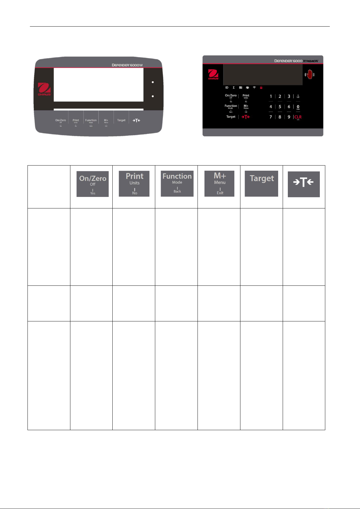
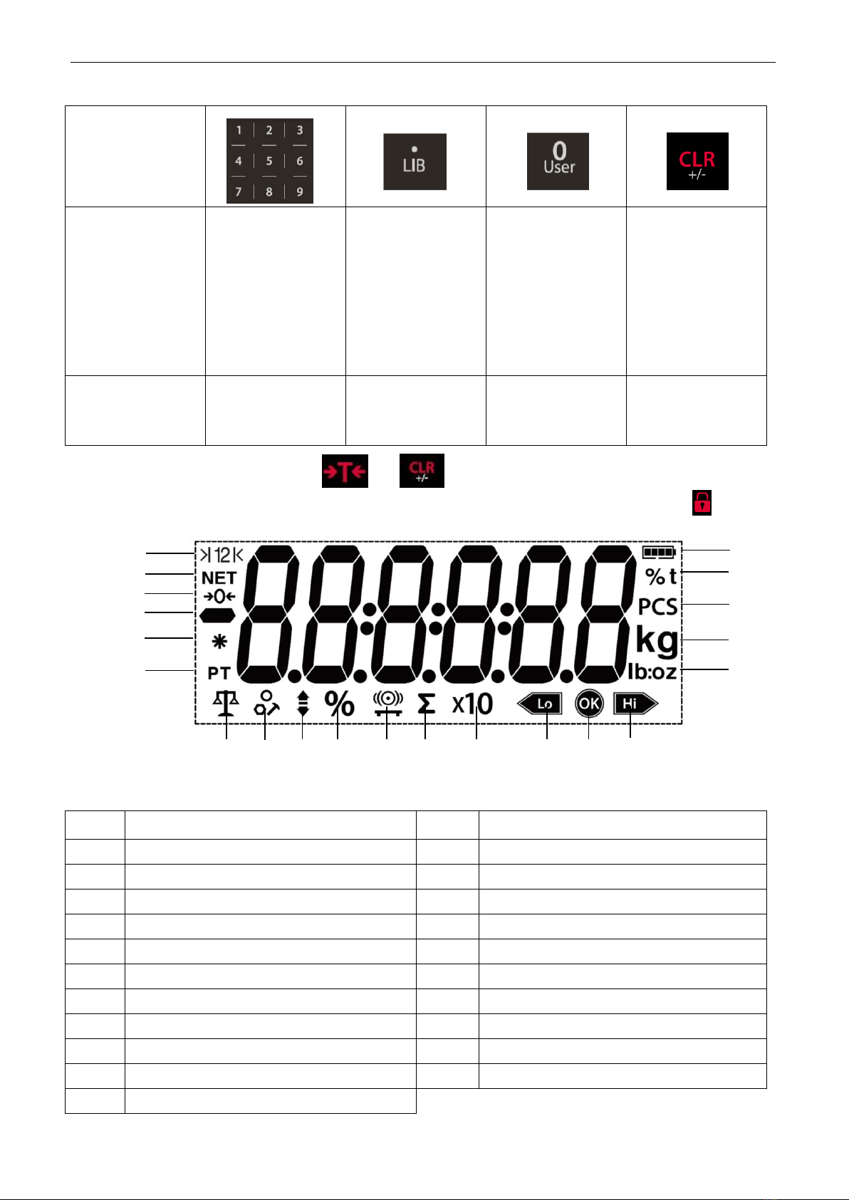
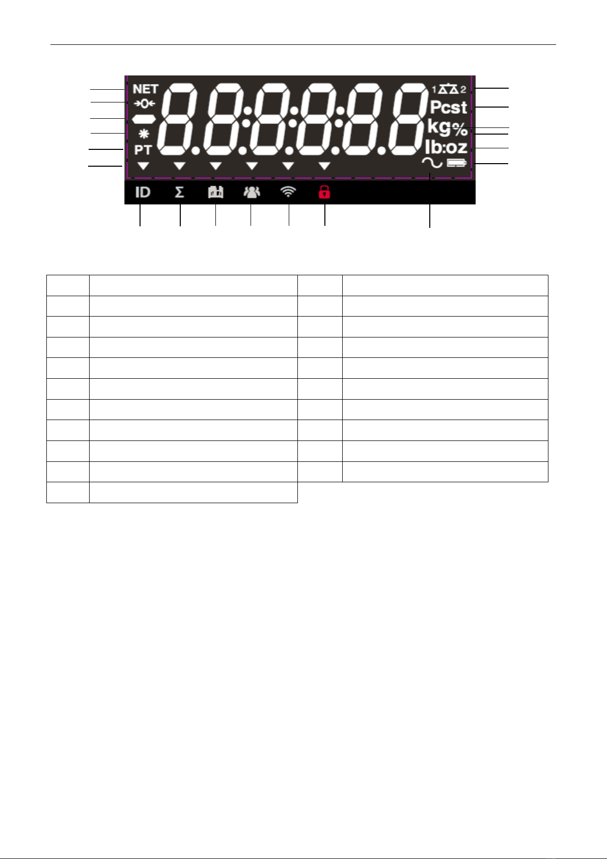
1.5. CONTROL FUNCTIONS ................................................................................................................................................... 6
2. INSTALLATION ..................................................................................................................................................9
2.1 UNPACKING ................................................................................................................................................................ 9
2.2 EXTERNAL CONNECTIONS............................................................................................................................................... 9
2.2.1 Scale Base with EasyConnectTM Connector...................................................................................................... 9
2.2.2 Power input to i-DT61PW................................................................................................................................ 9
2.2.3 AC Power to i-DT61XWE.................................................................................................................................. 9
2.3 INTERNAL CONNECTIONS ............................................................................................................................................... 9
2.3.1 Opening the Housing....................................................................................................................................... 9
2.3.2 Scale Base without EasyConnectTM Connector .............................................................................................. 11
2.3.3 Communication Interface Cable to i-DT61PW............................................................................................... 14
2.3.4 RS232 Interface Cable to i-DT61XWE ............................................................................................................ 15
2.4 MOUNTING BRACKET.................................................................................................................................................. 15
3. OPERATION .................................................................................................................................................... 16
3.1 TURNING THE SCALE ON/OFF....................................................................................................................................... 16
3.2 WEIGHING MODE...................................................................................................................................................... 16
3.2.1 Enter the Mode and Start Weighing ............................................................................................................. 16
3.2.2 Accumulation and Statistics .......................................................................................................................... 16
3.2.3 Check............................................................................................................................................................. 17
3.2.4 Application Settings ...................................................................................................................................... 18
3.3 COUNTING MODE ...................................................................................................................................................... 19
3.3.1 Enter the Mode ............................................................................................................................................. 19
3.3.2 Establish an APW .......................................................................................................................................... 19
3.3.3 Start Counting ............................................................................................................................................... 19
3.3.4 Application Settings ...................................................................................................................................... 19
3.4 PERCENT MODE ........................................................................................................................................................ 20
3.4.1 Enter the Mode ............................................................................................................................................. 20
3.4.2 Establish a Reference Weight........................................................................................................................ 20
3.4.3 Start Percent Weighing ................................................................................................................................. 20
3.4.4 Application Settings ...................................................................................................................................... 20
3.5 DYNAMIC MODE........................................................................................................................................................ 21
3.5.1 Enter the Mode ............................................................................................................................................. 21
3.5.2 Start Dynamic Weighing ............................................................................................................................... 21
3.5.3 Application Settings ...................................................................................................................................... 21
3.6 FILLING MODE........................................................................................................................................................... 22
3.6.1 Enter the Mode ............................................................................................................................................. 22
3.6.2 Start Filling .................................................................................................................................................... 22
3.6.3 Resume and Pause Filling.............................................................................................................................. 22
3.6.4 Display of the Dot Matrix Screen................................................................................................................... 22
3.6.5 Application Settings ...................................................................................................................................... 23
4. MENU SETTINGS............................................................................................................................................. 24
4.1 MENU NAVIGATION ................................................................................................................................................... 24
4.1.1 User Menu..................................................................................................................................................... 24
4.1.2 Button Navigation......................................................................................................................................... 25
4.2 CALIBRATION MENU................................................................................................................................................... 26
4.2.1 Initial Calibration........................................................................................................................................... 26
4.2.2 Zero Calibration [
ZErO
].................................................................................................................................. 26
4.2.3 Span Calibration [
SpaN
]................................................................................................................................. 26
4.2.4 Linearity Calibration [
LIN
]............................................................................................................................. 27
4.2.5 GEO Adjustment [
GEO
]................................................................................................................................... 27
4.2.6 Calibration Test [
C.test
] ............................................................................................................................... 28

EN-2 Defender 6000 Indicators
4.2.7 End Cal [End] ................................................................................................................................................. 28
4.3 SETUP MENU ............................................................................................................................................................ 29
4.4 READOUT MENU ....................................................................................................................................................... 33
4.5 UNIT MENU.............................................................................................................................................................. 35
4.6 GLP/GMP MENU..................................................................................................................................................... 35
4.7 COMMUNICATION...................................................................................................................................................... 36
4.7.1 RS232 Menu .................................................................................................................................................. 36
4.7.2 Print Menu .................................................................................................................................................... 37
4.7.3 RS485 Configuration ..................................................................................................................................... 40
4.7.4 Ethernet Configuration.................................................................................................................................. 40
4.7.5 Analog Configuration .................................................................................................................................... 40
4.8 MEMORY ................................................................................................................................................................. 40
4.8.1 Memory menu (for i-DT61PW model)........................................................................................................... 40
4.8.2 USB memory (for i-DT61XWE model)............................................................................................................ 40
4.8.3 Alibi Memory (for i-DT61XWE model) ........................................................................................................... 41
4.9 DISCRETE I/O (FOR I-DT61XWE MODEL) ...................................................................................................................... 46
4.9.1 I/O Type......................................................................................................................................................... 46
4.9.2 Input.............................................................................................................................................................. 47
4.9.3 Output ........................................................................................................................................................... 47
4.10 LOCK KEY CONFIGURATION .......................................................................................................................................... 47
4.11 LIBRARY (FOR I-DT61XWE MODEL).............................................................................................................................. 48
4.12 USER (FOR I-DT61XWE MODEL).................................................................................................................................. 50
4.13 USB (FOR I-DT61XWE MODEL) .................................................................................................................................. 52
4.13.1 USB Flash Drive ............................................................................................................................................. 52
4.13.2 RFID ............................................................................................................................................................... 52
4.13.3 Barcode ......................................................................................................................................................... 52
4.13.4 Keyboard ....................................................................................................................................................... 52
4.13.5 Wi-Fi/Bluetooth Dongle (Optional) ............................................................................................................... 53
5. LEGAL FOR TRADE........................................................................................................................................... 55
5.1 SETTINGS.................................................................................................................................................................. 55
5.2 VERIFICATION............................................................................................................................................................ 55
5.3 SEALING ................................................................................................................................................................... 55
6. MAINTENANCE ............................................................................................................................................... 57
6.1 CLEANING................................................................................................................................................................. 57
6.1.1 Cleaning for i-DT61PW Model....................................................................................................................... 57
6.1.2 Cleaning for i-DT61XWE Model..................................................................................................................... 57
6.2 TROUBLESHOOTING .................................................................................................................................................... 58
6.3 SERVICE INFORMATION ............................................................................................................................................... 58
7. TECHNICAL DATA............................................................................................................................................ 59
7.1 SPECIFICATIONS ......................................................................................................................................................... 59
7.2 TABLE OF GEO VALUES................................................................................................................................................ 61
8. COMPLIANCE.................................................................................................................................................. 62
9. APPENDICES ................................................................................................................................................... 64
9.1 APPENDIX A.............................................................................................................................................................. 64
9.2 APPENDIX B.............................................................................................................................................................. 66

Defender 6000 Indicators EN-3
1. INTRODUCTION
This manual contains installation, operation and maintenance instructions for i-DT61PW and i-DT61XWE
indicators. Please read it completely before installation and operation.
1.1. Safety Precautions
Definition of Signal Warnings and Symbols
Safety notes are marked with signal words and warning symbols. These show safety issues and warnings.
Ignoring the safety notes may lead to personal injury, damage to the instrument, malfunctions and false results.
WARNING
For a hazardous situation with medium risk, possibly resulting in severe injuries or
death if not avoided.
CAUTION
For a hazardous situation with low risk, resulting in damage to the device or the
property or in loss of data, or minor or medium injuries if not avoided.
ATTENTION
For important information about the product. May lead to equipment damage if not
avoided.
NOTE
For useful information about the product.
Warning Symbols
General hazard
Explosion hazard
Electrical shock hazard
Safety Precautions
CAUTION: Read all safety warnings before installing, making connections, or servicing this equipment.
Failure to comply with these warnings could result in personal injury and/or property damage. Retain
all instructions for future reference.
Before connecting power, verify that the AC adapter’s input voltage range and plug type are
compatible with the local AC mains power supply.
Do not position the equipment such that it is difficult to reach the power connection.
Only connect the power cord to a compatible grounded electrical outlet.
Make sure that the power cord does not pose a potential obstacle or tripping hazard.
Operate the equipment only under ambient conditions specified in these instructions.
The equipment is for indoor use only.
Do not operate the equipment in hazardous or unstable environments.
Do not place the equipment upside down on the platform.
Use only approved accessories and peripherals.
Disconnect the equipment from the power supply when cleaning.
Service should only be performed by authorized personnel.
WARNING: Never work in an environment subject to explosion hazards! The housing of the instrument
is not gas tight. (Explosion hazard due to spark formation, corrosion caused by the ingress of gases).
WARNING: Electrical shock hazards exist within the housing. The housing should only be opened by
authorized and qualified personnel. Remove all power connections to the unit before opening.
1.2. Intended Use
This instrument is intended for use in light industry. It must only be used for measuring the parameters
described in these operating instructions. Any other type of use and operation beyond the limits of technical
specifications, without written consent from OHAUS, is considered as not intended. This instrument complies
with current industry standards and the recognized safety regulations; however, it can constitute a hazard in
use. If the instrument is not used according to these operating instructions, the intended protection provided by
the instrument may be impaired.

EN-4 Defender 6000 Indicators
1.3. Overview of Parts and Controls
Figure 1-1 i-DT61PW Indicator
Figure 1-2 i-DT61XWE Indicator
Item
Description
1
Control Panel
2
Front Housing
3
Screws (4)
4
Load Cell Connector
5
Bottom Housing
6
Strain Relief for Option
7
Power cord
Item
Description
1
Control Panel
2
Front Housing
3
Screws (6)
4
Adjusting Knobs (2)
5
Mounting Bracket
6
Load Cell Connector
7
Rear Housing
1
2
3
4
5
6
7
1
v
2
3
4
5
6
7

Defender 6000 Indicators EN-5
1.4. Mainboard
.Figure 1-3 i-DT61PW Mainboard
Item
Description
1
IR Communication connector (J6)
2
Security Switch (SW1)
3
Load Cell connector (J7)
4
Load Cell Terminal Block (J8)
Figure 1-4 i-DT61XWE Mainboard
Item
Description
Item
Description
1
Alibi Memory Board connector (J19)
6
Keyboard connector (J1)
2
Discrete I/O/Analog/RS232-RS485-USB
Device connector (J11)
7
Load Cell connector (J12)
3
Display Board connector (J2)
8
Load Cell Terminal Block (J3)
4
Ethernet connector (J10)
9
Security Switch connector (SW1)
5
RS232 connector (J5)
10
Discrete Input0 (J16)
1
2
3
4
1
2
3
4
5
6
9
7
8
10

EN-6 Defender 6000 Indicators
1.5. Control Functions
i-DT61PW Control Panel i-DT61XWE Control Panel
Button
Primary
Function
(Short Press)
On/Zero
If the
terminal is
Off, press to
power on;
If the
terminal is
On, press to
set the zero
point.
Print
Sends the
current value
to the
selected
COM ports if
AUTOPRINT
is disabled.
Function
Initiates an
application
mode.
M+
Accumulates
the weight or
displays the
accumulated
information
with no load
on the pan.
Target
Sets
under/over
limit value for
Check.
Tare
Enters/clears
a tare value;
When the
accumulation
data is
displayed,
press to
clear them.
Secondary
Function
(Long Press)
Off
If the
terminal is
On, press to
power off.
Units
Changes the
weighing
unit.
Mode
Allows
changing the
application
mode.
Menu
Enters the
user menu.
Target
Shows
under/over
limit value for
Check.
Tare
Displays the
tare weight.
Menu
Function
(Short Press)
Yes
Accepts the
current
setting on
the display.
No
Advances to
the next
menu or
menu item.
Rejects the
current
setting on
the display
and
advances to
the next
available
one.
Back
Moves back
to the
previous
menu item.
Exit
Exits the
user menu.
Aborts the
calibration in
progress.
Notes:
Short Press: press less than 1 second.
Long Press: press and hold for more than 2 seconds.

Defender 6000 Indicators EN-7
Numeric keyboard (i-DT61XWE)
Primary Function
(Short Press)
1-9
Enters numeric
values.
.
Enters decimal
point (.).
0
Enters numeric
values 0.
CLR
Clears the entered
value.
Clears an existing
APW.
When the
accumulation data
is displayed, press
to clear them.
Secondary
Function
(Long Press)
LIB
Searches library
items with numeric
keys.
User
Searches users
with numeric keys.
+/-
Switches between
positive and
negative values.
Note: for i-DT61XWE model, press the and button together for three seconds can lock all
buttons. Perform the same procedure again to unlock all buttons. When all buttons are locked, the icon will
be lighted.
Figure 1-5 i-DT61PW Display
Item
Description
Item
Description
1
Range symbol(not used)
12
Accumulation symbol
2
NET symbol
13
Resolution extension symbol(not used)
3
Center of Zero symbol
14
Check weighing lower symbol
4
Negative symbol
15
Acceptable symbol
5
Stable weight symbol
16
Check weighing higher symbol
6
Preset Tare, Tare symbols
17
Pound, Ounce, Pound:Ounce symbols
7
Weighing mode symbol
18
Kilogram, gram symbols
8
Counting mode symbol
19
Pieces symbol
9
Check weighing mode symbol
20
Percent symbol, tonne symbol (not used)
10
Percentage weighing mode symbol
21
Battery symbol
11
Dynamic weighing mode symbol
1
2
3
4
5
6
7
8
9
10
11
12
13
14
15
16
17
18
19
20
21

EN-8 Defender 6000 Indicators
Figure 1-6 i-DT61XWE Display
Item
Description
Item
Description
1
NET symbol
11
Wi-Fi symbol
2
Center of Zero symbol
12
Lock symbol
3
Negative symbol
13
Dynamic (tilde) symbol
4
Stable weight symbol
14
Battery symbol (not use)
5
Preset Tare, Tare symbols
15
Pound, Ounce, Pound:Ounce symbols
6
Pointer symbols
16
Percent symbol
7
ID symbol
17
Kilogram, gram symbols
8
Accumulation symbol
18
Pieces symbol, tonne symbol (not used)
9
Library symbol
19
Scale symbol (not used)
10
User symbol
1
2
3
4
5
6
7
8
9
10
11
12
13
14
15
16
17
18
19

Defender 6000 Indicators EN-9
2. INSTALLATION
2.1 Unpacking
Unpack the following items:
i-DT61PW or i-DT61XWE indicator
6 cells of D size dry batteries (i-DT61PW only)
Mounting bracket
Knobs (2)
Quick installation guide
Instruction manual
2.2 External Connections
2.2.1 Scale Base with EasyConnectTM Connector
To connect the OHAUS scale base with EasyConnectTM connector to the terminal, plug the base's connector
onto the external load cell connector located at the bottom of the terminal. Then rotate the base connector’s
locking ring clockwise. Check the following illustration for details.
2.2.2 Power input to i-DT61PW
Use 6 cells of D size dry batteries. During battery operation, the battery symbol indicates the battery status.
Battery 5%~25% remaining
Battery 25%~50% remaining
Battery 50%~75% remaining
Battery 75%~100% remaining
2.2.3 AC Power to i-DT61XWE
Connect the AC plug to an electrical outlet.
2.3 Internal Connections
Some connections require the housing to be opened.
2.3.1 Opening the Housing
CAUTION: ELECTRICAL SHOCK HAZARD. REMOVE ALL POWER CONNECTIONS TO THE
INDICATOR BEFORE SERVICING OR MAKING INTERNAL CONNECTIONS. THE HOUSING
SHOULD ONLY BE OPENED BY AUTHORIZED AND QUALIFIED PERSONNEL, SUCH AS
AN ELECTRICAL TECHNICIAN.
i-DT61PW
1. Remove the six Phillips head screws from the rear housing.
2. Remove the front housing. Be careful not to disturb the internal connections.
i-DT61XWE
i-DT61PW

EN-10 Defender 6000 Indicators
3. Once all connections are made, re-attach the front housing.
i-DT61XWE
1. Remove the four hex head screws from the bottom housing.
2. Open the housing by carefully pulling the bottom housing backward.
3. Once all connections are made, re-attach the bottom housing.
Note: The screws should be tightened to 2.5 N•m (20-25 in-lb) torque to ensure a watertight seal.

Defender 6000 Indicators EN-11
2.3.2 Scale Base without EasyConnectTM Connector
For connecting bases (which do not have the EasyConnectTM connector) to an i-DT61PW or an i-DT61XWE, a
load cell cable gland kit (P/N 30379716) is available as an accessory.
Removing the pre-installed Load Cell connector and wiring harness.
Before making the connections, remove the pre-installed load cell connector and wiring harness by following
the following steps.
i-DT61PW
1. Remove the 6 Phillips head screws, and open the rear housing by carefully pulling the front housing
forward.
2. Unplug the white load cell connectors from the main housing (two circles).
3. Open the front housing by removing the 12 Phillips head screws.
4. Unplug the white load cell connectors from the main PCBA board.

EN-12 Defender 6000 Indicators
i-DT61XWE
1. Place the terminal down, and unscrew the screws marked in the following graphic.
2. Pull out the bottom of the terminal.
3. Use a screw driver to unscrew the sealing cover.

Defender 6000 Indicators EN-13
4. Pull the protruding part of the sealing cover a little forward to release it.
5. Remove the sealing cover and then unplug the white load cell connectors.
Installing Load Cell Cable and Connectors
In order to meet certain electrical noise emission limits and to protect i-DT61PW and i-DT61XWE from external
influences, it is necessary to install a ferrite core on the load cell cable connected to the terminal. The ferrite
core is included with the terminal.
To install the ferrite, simply route the cable through the center of the core and then take one wrap around the
outside of the core and route the cable through the center again. Either the complete cable or the individual
wires can be wrapped through the ferrite. This should be done as close to the enclosure as possible. See
Figure 2-1.
Figure 2-1

EN-14 Defender 6000 Indicators
Load Cell
Terminal
Blocks
Main Board Wiring Connections
Once the i-DT61PW and i-DT61XWE enclosure is opened, connections can be made to the terminal blocks on
the main board as shown in Figure 2-2.
i-DT61PW
i-DT61XWE
Figure 2-2
Jumper Connections
The i-DT61PW and i-DT61XWE indicators are designed to support both 2mV/V and 3mV/V load cells from the
same circuitry. A load cell output rating selection jumper is not required.
Figure 2-3 shows the terminal definitions for the analog load cell terminal blocks. Note that when using four
-wire load cells, jumpers must be placed between the +Excitation and +Sense terminals and between the
-Excitation and -Sense terminals.
Figure 2-3 Jumper Connections
After wiring is completed, replace the indicator housing screws. Make sure the water-proof cable gland is
properly tightened.
2.3.3 Communication Interface Cable to i-DT61PW
Attach the IR Communication cable (P/N: 30572910) to the indicator front panel, make sure the two holes in the
interface cable module match the two bolts which located in the front panel.
Pin
Connection
J3-1
+EXC
J3-2
+SEN
J3-3
+SIN
J3-4
GND
J3-5
-SIN
J3-6
-SEN
J3-7
-EXC
Figure 2-4
J3-1
J3-2
J3-3
J3-4
J3-5
J3-6
J3-7

Defender 6000 Indicators EN-15
2.3.4 RS232 Interface Cable to i-DT61XWE
Pass the optional RS232 cable through the strain relief and attach it to the RS232 connector on the mainboard.
Tighten the strain relief to maintain a watertight seal. Please refer to Figure 2-7 for the postion of the
serial port connector RXD TXD and GND.
Note:
Please refer to Opeing the Housing section for how to open the case of the terminal.
For details about Discrete Input0 function, please refer to the Discrete I/O (for i-DT61XWE) section for
details.
2.4 Mounting Bracket
Attach the bracket to a wall or table using fasteners (not supplied) that are appropriate for the type of mounting
surface. The bracket will accommodate up to 6 mm (1/4”) diameter screws. Locate the mounting holes as
shown in Figure 2-8 and 2-9.
Figure 2-8 i-DT61PW
Mounting Bracket Dimensions
RS232
connector
Figure 2-5
Strain Relief for Option
Figure 2-6 RS232 connector on the
mainboard
Figure 2-9 i-DT61XWE
Mounting Bracket Dimensions
Figure 2-7
RS232 connector
Discrete Input0

EN-16 Defender 6000 Indicators
3. OPERATION
3.1 Turning the Scale On/Off
To turn the scale on, press and hold the On/Zero Off button for 1 second. The scale performs a display test,
momentarily displays the software version, and then enters the active weighing mode.
To turn the scale off, press and hold the On/Zero Off button until OFF is displayed.
3.2 Weighing Mode
Use this application to determine the weight of items in the selected unit of measure. This mode is the factory
default setting.
3.2.1 Enter the Mode and Start Weighing
To enter the weighing mode from any application mode:
1. Press and hold the Mode button until wWeIGH is displayed.
2. If needed, place an empty container on the pan and press the button to tare.
3. Add sample to the pan or container. The display shows the weight of the sample.
Note: Please refer to the Check section for how to use Check in the Weighing mode.
3.2.2 Accumulation and Statistics
The Accumulation feature enables manual or automatic totalizing of displayed values. Statistical data (total
accumulated weight, min/max weights, pieces, percent, and total number of samples) is stored in memory for
review and printing. Accumulation works together with each application mode except Filling, but the
accumulation data will be cleared when change to another mode.
3.2.2.1 Settings
There are four accumulation options:
Off (OFF): disable accumulation function.
Manual (mMANU): press the M+ button to do acuumulation manually.
Auto (AUtO): the scale will perform accumulation automatically.
Accept (ACCEPt): the scale will perform accumulation automatically in the Check mode when the weight
on the pan is acceptable between the under and over value you set.
To set accumulation options:
1. Long press the Menu button until you see C.A.L.
2. Short Press the No button one time. When you see S.E.t.U.P, press the Yes button.
3. Short Press the No button several times to navigate until you see ACCUmM. Press the Yes button.
4. Short Press the No button several times to select the accumulation option you want. The four options have
been introduced above. Then press the Yes button to confirm.
5. Press the Exit button to exit.
3.2.2.2 Accumulation
Manual
Place the item on the scale and press the M+ button to add the weight to accumulation. The ∑ pointer will keep
flashing until the weight is removed and the platform is stable.
Auto
Place the item on the scale. The displayed value is accumulated automatically. The ∑ pointer will keep flashing
until the weight is removed and the platform is stable.
Accept
Place the item on the scale in check mode. The displayed value is accumulated automatically when the weight
is acceptable between the under and over value you set.
3.2.2.3 Viewing and Clearing Statistical Data
When the pan is cleared, press the M+ button to view the accumulation and statistics results.
To clear the accumulation data, press the CLR button on i-DT61XWE terminal or the button on i-
DT61PW terminal while the statistical information is displayed. When the display shows Clr.aCC, press the

Defender 6000 Indicators EN-17
Yes button to clear the stored data and return to current mode.
Notes:
The item must be removed from the pan before the next item can be accumulated.
Only stable weights are stored.
Changing modes will clear the stored accumulation data.
When Legal for Trade is turned ON, for NTEP, gross and net weight cannot be added to the same total.
If the first weight is recorded in gross, the future ones should be recorded in the same way. It is the same
for net weight.
3.2.3 Check
Use this application to compare the weight of items to a target weight range. This mode is available for
Weighing, Counting, Percent, and Dynamic.
3.2.3.1 Set Check Limits
i-DT61PW
1. Press the Target button from Weighing, Counting, Percent or Dynamic mode to set check limits.
2. The display shows UNDEr.
3. Press the Yes button to edit the under value.
4. If there is a stored under value of the last time, the display will show it. For example: 1.0kg.
Press the Yes button if you want to use this value. Then the display shows OuEr.
Press the No button if you do not want to use this value, and skip to step 6.
5. If there is no stored value, the display shows 000000.
6. To set a new under value, short press the No button several times until the desired number appears. Short
press the Yes button to accept the number and move to the next digit. Repeat the process until all the
digits are correct. Press the Yes button to accept the value. Then the display shows OuEr.
7. Repeat step 2 to 6 to set the over value.
8. If the values you set are invalid, the display will show --NO-- and go back to reset.
9. If the values you set are valid, the display will go to check weighing screen.
i-DT61XWE
1. Press the Target button from Weighing, Counting, Percent or Dynamic mode to set check limits.
2. The display shows UNDEr.
3. Press the Yes button to edit the under value.
4. If there is a stored under value of the last time, the display will show it.
Press the Yes button if you want to use this value.
Press the No button if you do not want to use this value or do not have a stored value. Input the
needed one with the numeric keypad. Press the Yes button to accept the under value.
5. The display will show OuEr.
6. Repeat step 2 and 3 to set the over value.
7. If the values you set are invalid, the display will show --NO-- and go back to reset.
8. If the values you set are valid, the display will go to check weighing screen.
3.2.3.2 Positive Check
Positive check is used to determine when the material added to the scale is within the target range. In this case
the under and over values must be positive values. (The over value must be greater than the under value.)
Add material to the scale platform until the display shows it is within the Accept (green) range.
3.2.3.3 Negative Check
Negative check is used to determine when the material removed from the scale is within the target range. In
this case the under and over values are both negative values. The under value must be greater than the over
value. (For example: the under value is -10; the over value is -15).
Place the item to be weighed on the scale and press the button.
Remove a portion of the item until it is within the acceptable range.
3.2.3.4 Zero Check
Zero check is used when comparing subsequent samples to an initial reference sample. In this case, the under
value must be a negative value and the over value must be a positive one.
Place the reference item on the scale and press the button.
Remove material from the scale platform until the display shows it is within the Accept (green) range.

EN-18 Defender 6000 Indicators
3.2.3.5 Clear Check Limits
Long press the Target button until the display shows the under and over values.
Press the CLR button of i-DT61XWE indicator or the button of i-DT61PW indicator, the display shows
Clr.CHk. Press the Yes button to clear both the under and over values.
3.2.4 Application Settings
The application can be customized for user preferences.
To enter application settings:
1. Long press the Menu button until you see C.A.L. Short press the No button several times until you see
mM.O.d.E. Press the Yes button to enter the application mode settings.
2. Short press the No button several times to navigate until you see the selection you want.
3. Press the Yes button to select.
4. Repeat step 2 and 3 several times until you finish all settings.
5. Press the Exit button to exit.
The Weighing Configurations are defined below (defaults in Bold).
Item
Available Settings
Comments
Weighing (wWeIGH)
On, Off
To enable Weighing
Note: you cannot disable Weighing if you are in the mode currently.
This manual suits for next models
1
Table of contents
Other OHAUS Measuring Instrument manuals

OHAUS
OHAUS STARTER 300C User manual

OHAUS
OHAUS Defender T24PE User manual

OHAUS
OHAUS ST Series User manual

OHAUS
OHAUS MB45 User manual

OHAUS
OHAUS MB25 User manual

OHAUS
OHAUS MB90 User manual

OHAUS
OHAUS STARTER 3100M User manual

OHAUS
OHAUS TD52 User manual

OHAUS
OHAUS MB120 User manual

OHAUS
OHAUS MB120 User manual

OHAUS
OHAUS i-DT33XW User manual

OHAUS
OHAUS ST20C-A User manual

OHAUS
OHAUS starter 3100 User manual

OHAUS
OHAUS STARTER 5000 User manual

OHAUS
OHAUS TD32PE User manual

OHAUS
OHAUS STARTER 5000 User manual

OHAUS
OHAUS MB27 User manual

OHAUS
OHAUS STARTER 2100 User manual

OHAUS
OHAUS T51 Use and care manual

OHAUS
OHAUS CD-1 User manual