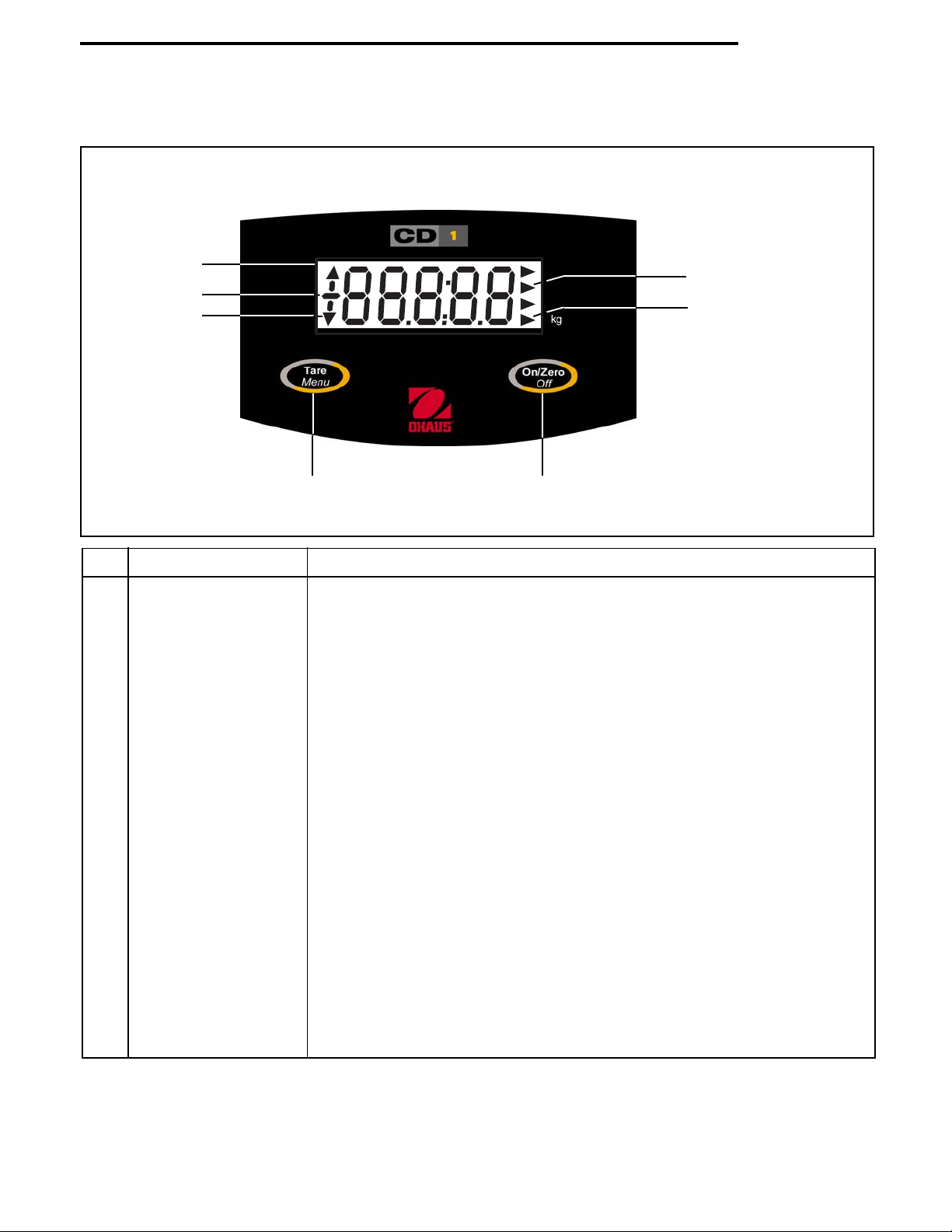
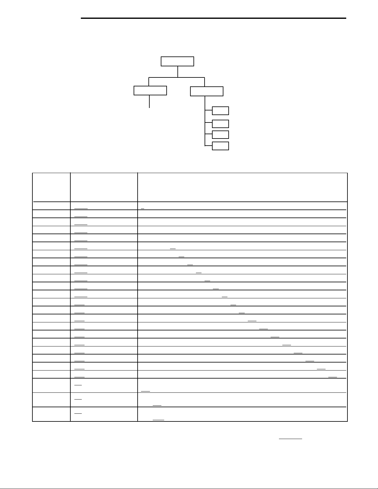
OHAUS CD-1 User manual

INSTRUCTION MANUAL
Model CD-1 Indicator
MANUAL DE INSTRUCCIONES
Indicador modelo CD-1
MANUEL DE LUTILISATEUR
Indicateur modèle CD-1


Ohaus Corporation, 19A Chapin Road, P.O. Box 2033, Pine Brook, NJ, 07058, U A
Declaration of Conformit We, Ohaus Corporation, declare under our sole responsibility that the indicator model listed below marked
with "CE" are in conformity with the directives and standards mentioned.
Indicator model CD-1
Marked with: EC Directive (Including applicable amendments) Standard
73/23/EC EN60950:1992
Electrical equipment for use within specified voltage limits afety of Information Technology Equipment
89/336/EC EN61326:1997 + A1:1998
Electromagnetic compatibility Electrical Equipment for Measurement, Control and Laboratory Use -
EMC requirements
ISO 9001 Registration for Ohaus Corporation.
Ohaus Corporation, U A, was examined and evaluated in 1994 by the Bureau Veritas Quality
International (BVQI) and was awarded I O 9001 registration. This certifies that Ohaus Corporation, U A, has a quality system that conforms with the
international standards for quality management and quality assurance (I O 9000 series). Repeat audits are carried out by BVQI at intervals to check
that the quality system is operated in the proper manner.
FCC NOTE: THI EQUIPMENT HA BEEN TE TED AND FOUND TO COMPLY WITH THE LIMIT FOR A CLA A DIGITAL DEVICE, PUR UANT
TO PART 15 OF THE FCC RULE .
THE E LIMIT ARE DE IGNED TO PROVIDE REA ONABLE PROTECTION AGAIN T HARMFUL INTERFERENCE WHEN THE EQUIPMENT I
OPERATED IN A COMMERCIAL ENVIRONMENT. THI EQUIPMENT GENERATE , U E , AND CAN RADIATE RADIO FREQUENCY ENERGY
AND, IF NOT IN TALLED AND U ED IN ACCORDANCE WITH THE IN TRUCTION MANUAL, MAY CAU E HARMFUL INTERFERENCE TO
RADIO COMMUNICATION . OPERATION OF THI EQUIPMENT IN A RE IDENTIAL AREA I LIKELY TO CAU E HARMFUL INTERFERENCE IN
WHICH CA E THE U ER WILL BE REQUIRED TO CORRECT THE INTERFERENCE AT HI OWN EXPEN E.
Ted Xia
President
Ohaus Corporation, Pine Brook, NJ U An
THI DIGITAL APPARATU DOE NOT EXCEED THE CLA A LIMIT FOR RADIO NOI E EMI ION FROM DIGITAL APPARATU A ET OUT IN
THE INTERFERENCE-CAU ING EQUIPMENT TANDARD ENTITLED DIGITAL APPARATU , ICE -003 OF THE DEPARTMENT OF COMMUNICA-
TION CANADA.
CET APPAREIL NUMERIQUE RE PECTE LE LIMITE DE BRUIT RADIOELECTRIQUE APPLICABLE AUX APPAREIL NUMERIQUE DE CLA E
A PRE CRITE DAN LA NORME UR LE MATERIEL BROUILLEUR: APPAREIL NUMERIQUE , NMB-003 EDICTEE PAR LE MINI TRE DE
Unauthorized changes or modifications to this equipment are not permitted.
Last two digits of the year which the CE marking was affixed: 02

TABLE OF CONTENTS
1. GETTING TO KNOW YOUR CD-1 INDICATOR ................................................................................................................ 1
1.1 Introduction .............................................................................................................................................................. 1
1.1.1 Features ......................................................................................................................................................... 1
2. INSTALLATION .......................................................................................................................................................... 1
2.1 Unpacking and Checking............................................................................................................................................ 1
2.2 electing the Location ................................................................................................................................................ 2
2.3 Cautionary Notes ....................................................................................................................................................... 2
2.4 Connecting the CD-1 Indicator to a cale Base ............................................................................................................. 2
2.5 Connecting Power ..................................................................................................................................................... 2
2.5.1 AC Adapter....................................................................................................................................................... 2
2.5.2 Battery Installation ............................................................................................................................................ 2
3. SETUP...................................................................................................................................................................... 3
3.1 Overview of Controls and Display Functions ................................................................................................................. 3
3.2 Menu tructure .......................................................................................................................................................... 4
3.3 Available ettings ...................................................................................................................................................... 4
3.4 etup Procedure ........................................................................................................................................................ 5
3.5 Calibration Procedure ................................................................................................................................................. 6
4. OPERATION .............................................................................................................................................................. 7
4.1 Turning the CD-1 Indicator On/Off ................................................................................................................................ 7
4.2 Weighing .................................................................................................................................................................. 7
4.3 Zero Operation .......................................................................................................................................................... 7
4.4 Tare Operation .......................................................................................................................................................... 7
4.5 Clear Tare Operation .................................................................................................................................................. 8
5. CARE AND MAINTENANCE ......................................................................................................................................... 8
5.1 Troubleshooting ........................................................................................................................................................ 8
5.2 Error Codes List ......................................................................................................................................................... 8
5.3 ervice Information .................................................................................................................................................... 9
5.4 Accessories .............................................................................................................................................................. 9
6. TECHNICAL DATA...................................................................................................................................................... 9

1
CD-1 Indicator
1. GETTING TO KNOW YOUR CD-1 INDICATOR
1.1 Introduction
Thank you for deciding to purchase a CD-1 Indicator from Ohaus. The Ohaus CD-1 Indicator is a rugged, reliable,
electronic weight indicator designed for easy operation. The CD-1 Indicator can drive one analog load cell and provide
capacity selections up to 1,000kg.
The CD-1 Indicator operates from six Alkaline AA batteries and can also be powered externally using the supplied AC
adapter. A 0.9 inch / 2.3 centimeters high LCD provides easy visibility when working at distances from the indicator.
Two membrane switches are mounted on the front panel that enable simple set up procedures. A metal bracket with
hardware is included that permits mounting the indicator to a wall or table.
Behind your instrument stands OHAU , a leading manufacturer of precision Indicators, cales and Balances. An
Aftermarket Department with trained instrument technicians is dedicated to providing you with the fastest service pos-
sible in the event your instrument requires servicing. OHAU also has a Customer ervice Department to answer any
inquiries regarding applications and accessories.
To ensure you make full use of the possibilities offered by your CD-1 Indicator, please read the manual completely
before installation and operation.
1.1.1 Features
Major features include:
1:10,000 maximum displayed resolution
Durable AB plastic housing in a compact industrial design
imple 2 function raised membrane buttons with Tare
5-digit, 7-segment, 0.9 inch / 2.3 centimeter high LCD display
Kilogram weight unit
AC or battery power
Load Cell Connector
Wall mount hardware
Battery saving Auto hut-off after five minutes of inactivity (when operated on batteries)
2. INSTALLATION
2.1 Unpacking and Checking
Open the package and remove the instrument and the accessories. Check the instrument for transport damage. Imme-
diately inform your Ohaus dealer if you have complaints or if parts are missing. Your CD-1 Indicator package should
contain:
CD-1 Indicator Instruction Manual Mounting Bracket
Mounting crews (2) AC power adapter Warranty card
crew anchors (2) Load Cell Connector
tore all parts of the packaging. This packaging ensures the best possible protection for the transport of your instrument.

2
CD-1 Indicator
2.2 Selecting the Location
The CD-1 Indicator should be used in an environment which is free from vibration, temperature or humidity extremes.
These factors will affect displayed weight readings. cale bases used with the CD-1 Indicator should be located on a
stable, level surface and kept away from vibrating sources such as large machinery. Maximum accuracy will be
achieved when the working area is clean and vibration free.
2.3 Cautionar Notes
The CD-1 Indicator must not be operated in wet or hazardous areas.
Before connecting the AC adapter, verify that the indicated voltage corresponds to the local mains voltage.
2.4 Connecting the CD-1 Indicator to a Scale Base
The scale base is connected to the round, 4-pin connector located on the right side of the CD-1 Indicator. The mating
connector supplied in the packaging must be attached to the load cell cable. lide the connector shell over the load cell
cable. Orient as shown in the illustration. Refer to the scale base manufacturer's information to determine the proper
load cell connections. older the load cell cable to the connector contacts according to table 2-1 and refer to the the
connector illustration.
NOTE: Any extra load cell connection wires should be isolated and insulated.
TABLE 2-1. LOAD CELL CONNECTION .
Connector Pin No. Connection
1 - Excitation
2 - ignal
3 + ignal
4 + Excitation
2.5 Connecting Power
The CD-1 Indicator may be operated using the supplied AC Adapter, or with 6 Alkaline "AA" batteries (not supplied).
2.5.1 AC Adapter
Connect the AC Adapter connector to the receptacle located at the right-hand side of the CD-1 Indicator and
plug the adapter into a convenient outlet.
NOTICE:
The socket/outlet must be installed near
the equipment and shall be easil accessible.
2.5.2 Batter Installation
Open the battery cover on the bottom of the housing.
Insert 6 Alkaline "AA" batteries into position. Orient the batteries so that the positive (+) ends rest against the
reeds and the negative (-) ends against the springs.
NOTE: When the CD-1 Indicator is operated from batteries, the Auto hut-Off feature is automatically enabled to
extend battery life. When no activity occurs within a 5 minute period, the CD-1 Indicator shuts off. This
feature cannot be disabled.
AC ADAPTER CORD
4
3
1
2
CONNECTOR REAR VIEW
After soldering the wires to the contacts, thread the shell onto the receptacle. Tighten the strain relief clamp over the
load cell cable. Plug the connector into the mating connector on the Indicator and tighten the knurled nut.
STRAIN RELIEF
CLAMP KNURLED
NUT
SHELL CABLE RECEPTACLE
CONTACTS
CONNECTOR A EMBLY

3
CD-1 Indicator
No. Designation Function
1 Weight Display Displays current weight on scale.
2 Minus sign When displayed, indicates a negative value.
3 Down arrow When displayed, indicates reading is stable.
4Tare Menu button A short press enters the tare weight into memory.
A long press (2 seconds) enters the menu mode.
When in the menu mode, a short press changes the displayed menu or setting.
If a tare has been entered, a short press clears the tare when the platform is empty.
5 On/Zero Off button A short press turns the Indicator on when the Indicator is off.
A short press zeros the display when the Indicator is on. (If a Tare has been
entered, the tare is cleared and the display is zeroed).
A long press (2 seconds) turns the Indicator off.
When in the menu mode, a short press selects the displayed menu or setting.
6 kg arrow When displayed, indicates unit of measure (kilograms).
7 NET arrow When displayed, indicates reading is net weight.
3.1 Overview of Controls and Displa Functions
1
3
45
6
7
3. SETUP
2NET

4
CD-1 Indicator
3.2 Menu Structure
The following table illustrates the menu structure in the CD-1 Indicator.
CAL EtuP
Perform F (Full cale Capacity) submenu
g (Graduation size) submenu
CP (Calibration Point) submenu
CAL ? (Calibration ?)
MENU
3.3 Available Settings
Table 3-1 shown below indicates the available settings that can be made in the EtuP menu.
TABLE 3-1 ETUP.
Full Scale Graduation Size1,2,3 Calibration Point 1,2
Capacit 1(gxxxx) (CPxxxx)
(FSxxxx)
10.001 1
20.001, 0.002 1,2
30.001, 0.002 1, 2, 3
50.001, 0.002, 0.005 1, 2, 3, 5
60.001, 0.002, 0.005 1, 2, 3, 5, 6
10 0.001, 0.002, 0.005, 0.01 1, 2, 3, 5, 6, 10
15 0.002, 0.005, 0.01 1, 2, 3, 5, 6, 10, 15
20 0.002, 0.005, 0.01, 0.02 1, 2, 3, 5, 6, 10, 15, 20
25 0.005, 0.01, 0.02 1, 2, 3, 5, 6, 10, 15, 20, 25
30 0.005, 0.01, 0.02 1, 2, 3, 5, 6, 10, 15, 20, 25, 30
40 0.005, 0.01, 0.02 1, 2, 3, 5, 6, 10, 15, 20, 25, 30, 40
50 0.005, 0.01, 0.02, 0.05 1, 2, 3, 5, 6, 10, 15, 20, 25, 30, 40, 50
60 0.01, 0.02, 0.05 1, 2, 3, 5, 6, 10, 15, 20, 25, 30, 40, 50, 60
75 0.01, 0.02, 0.05 1, 2, 3, 5, 6, 10, 15, 20, 25, 30, 40, 50, 60, 75
100 0.01, 0.02, 0.05, 0.1 1, 2, 3, 5, 6, 10, 15, 20, 25, 30, 40, 50, 60, 75, 100
120 0.02, 0.05, 0.1 1, 2, 3, 5, 6, 10, 15, 20, 25, 30, 40, 50, 60, 75, 100, 120
150 0.02, 0.05, 0.1 1, 2, 3, 5, 6, 10, 15, 20, 25, 30, 40, 50, 60, 75, 100, 120, 150
200 0.02, 0.05, 0.1, 0.2 1, 2, 3, 5, 6, 10, 15, 20, 25, 30, 40, 50, 60, 75, 100, 120, 150, 200
250 0.05, 0.1, 0.2 1, 2, 3, 5, 6, 10, 15, 20, 25, 30, 40, 50, 60, 75, 100, 120, 150, 200, 250
300 0.05, 0.1, 0.2 1, 2, 3, 5, 6, 10, 15, 20, 25, 30, 40, 50, 60, 75, 100, 120, 150, 200, 250, 300
400 0.05, 0.1, 0.2 1, 2, 3, 5, 6, 10, 15, 20, 25, 30, 40, 50, 60, 75, 100, 120, 150, 200, 250, 300, 400
500 0.05, 0.1, 0.2, 0.5 1, 2, 3, 5, 6, 10, 15, 20, 25, 30, 40, 50, 60, 75, 100, 120, 150, 200, 250, 300, 400, 500
600 0.1, 0.2, 0.5 1, 2, 3, 5, 6, 10, 15, 20, 25, 30, 40, 50, 60, 75, 100, 120, 150, 200, 250, 300, 400, 500,
600
750 0.1, 0.2, 0.5 1, 2, 3, 5, 6, 10, 15, 20, 25, 30, 40, 50, 60, 75, 100, 120, 150, 200, 250, 300, 400, 500,
600, 750
1000 0.1, 0.2, 0.5, 1 1, 2, 3, 5, 6, 10, 20, 25, 30, 40, 50, 60, 75, 100, 120, 150, 200, 250, 300, 400, 500, 600,
750, 1000
Notes:
1 Full cale Capacity, Graduation ize and Calibration Point initial factory default settings are shown in bold.
2 Graduation ize and Calibration Point default settings for corresponding Full cale Capacity are shown underlined.
3 Graduation ize selections are limited to resolutions from 1:1000 to 1:10000.

5
CD-1 Indicator
3.4 Setup Procedure
The EtuP menu must be entered the first time the CD-1 Indicator is used to establish the scale base parameters.
Do not calibrate the Indicator prior to establishing parameters in the SEtuP menu.
This procedure sets up the operating parameters for the CD-1 Indicator to match the scale base.
Press and hold the Tare Menu button. MENU is displayed
while the button is pressed and indicates CAL when released.
Press the Tare Menu button again. EtUP is displayed.
Press the On/Zero Off button to enter the EtUP menu. The display shows the Full cale
sub-menu F xxxx, where xxxx is the rated capacity of the scale base in kilograms. The last
selection is shown. The initial factory default setting F 1 is shown as an example.
If the displayed setting is not the desired value, press the Tare Menu button to change to a
different setting. If the displayed setting is the desired value, press the On/Zero Off button
to store and move to the next sub-menu.
The display shows the Graduation ize sub-menu gxxxx, where xxxx is the readability in
kilograms. The initial factory default setting is g0.001. When the Full cale value is
changed, the graduation value is automatically changed to the corresponding default value
(Refer to Table 3-1).
If the displayed setting is not the desired value, press the Tare Menu button to change to a
different setting. If the displayed setting is the desired value, press the On/Zero Off button
to store and move to the next sub-menu.
The display shows the Calibration Point sub-menu CPxxxx, where xxxx is the calibration
point in kilograms. The default setting is CP 1. When the Full cale value is changed, the
calibration point value is automatically changed to match the full scale value.
If the displayed setting is not the desired value, press the Tare Menu button to change to a
different setting. If the displayed setting is the desired value, press the On/Zero Off button
to store and move to the next sub-menu. The display shows CAL ? (calibrate ?).
After the Indicator has been properly set up to match the scale base parameters, calibrate
the unit before using. To enter calibration, press the On/Zero Off button and start at step
3 in the Calibration Procedure.
If the menu settings were not changed, press the Tare Menu button to return to the weigh-
ing mode.

6
CD-1 Indicator
3.5 Calibration Procedure
The calibration procedure can be performed as often as necessary.
1. Make sure the scale base platform is empty, stable and level before starting calibration.
2. Press and hold the Tare Menu button. MENU is displayed while the
button is pressed and indicates CAL when released.
NOTE: The calibration process can be terminated at any time by pressing and holding the
On/Zero Off button until OFF is displayed.
3. Press the On/Zero Off button. -C- is displayed momentarily
(Indicator stores the zero load signal) followed by the calibration
weight value. CP 1 (1kg) is shown as an example.
4. Place the indicated calibration weight on the platform, then press the
On/Zero Off button. -C- is displayed (indicator stores the Cal point
load signal), followed momentarily by the indicated calibration
weight on the platform.
5. Remove the calibration weight from the scale base platform. The Indicator is now ready for
use.

7
CD-1 Indicator
4. OPERATION
Before using the CD-1 Indicator, make sure it has been properly set up and calibrated. Refer to ection 3 and review
settings.
4.1 Turning the CD-1 Indicator On/Off
With the CD-1 Indicator off, press the On/Zero Off button. All
segments of the display are displayed followed by the software
revision r x.x. The CD-1 Indicator then goes into the weighing mode.
The decimal point position may be different depending on the setup of the CD-1 Indicator.
To turn the CD-1 Indicator off, press and hold the On/Zero Off button until OFF is dis-
played.
4.2 Weighing
Once the CD-1 Indicator has been properly calibrated and zeroed, place the object to be
weighed on the platform.
4.3 Zero Operation
Press the On/Zero Off button to zero the CD-1 Indicator. If a tare has been entered, the tare
is cleared and the display is zeroed.
Auto-Zero Tracking - The automatic zero setting mechanism is permanently set to capture
changes of 1 d. No operator actions are required.
NOTE: The stable cursor must be lit to accept zero operation.
TABLE CUR OR
4.4 Tare Operation
When weighing objects that must be held in a container, taring stores the container weight in the CD-1 Indicators
memory. Taring is possible up to the full scale capacity where the tare value is subtracted from the available capacity.
The symbol is lit adjacent to NET on the front panel. To store the container weight, proceed as follows:
Place the container on the platform. ample shown is 50g.
Press the Tare Menu button. The scale is tared and shows Net weight.
NOTE: table cursor must be lit to accept tare operation.
If the tare weight is removed from the scale, the Net weight is displayed as a negative value.
TABLE CUR OR

8
CD-1 Indicator
4.5 Clear Tare Operation
To clear the tared weight stored in memory, press the Tare Menu button with no load on the scale base.
5. CARE AND MAINTENANCE
To keep the CD-1 Indicator operating properly, the housing should be kept clean and free from foreign material. If
necessary, a cloth dampened with water and a mild detergent may be used. Do not allow liquids to enter inside the
housing.
5.1 Troubleshooting
SYMPTOM
Unit will not turn on.
Will not zero when turned on.
Cannot zero indicator
Unable to calibrate unit.
REMEDY
Check power cord connections.
Make sure adapter connector is
plugged all the way into the Indi-
cator.
Check battery connector.
Check orientation of the batteries.
Replace batteries.
Remove excessive load on scale
base to less than 20% of scale ca-
pacity.
Remove disturbances.
Use correct calibration mass.
PROBABLE CAUSE(S)
Adapter not plugged in or properly
connected.
Batteries dead or not properly in-
stalled.
Load on scale base exceeds allow-
able 20 % of scale capacity.
cale base disturbances.
Incorrect value for calibration mass.
5.2 Error Codes List
The following list describes the various error codes and that can appear on the display.
Err 1 Over-range error is displayed when capacity plus 9d is reached.
Err 2 Under-range error is displayed when reading exceeds 9d below zero.
Err 21 Calibration data checksum error, calibration required.
CAL E Calibration error, indicating that the weights were placed in the wrong order, or an incorrect
weight was placed on the scale base platform.
Lo Low battery indication is displayed when approximately 20 minutes of battery operation
remains.

9
CD-1 Indicator
5.3 Service Information
For ervice assistance in the United tates, please call Aftermarket, Ohaus Corporation, toll-free at (800) 526-0659.
An Ohaus Product ervice pecialist will be available to help you.
For ervice assistance outside of the United tates, call your local dealer.
5.4 Accessories
No accessories are available for this product.
6. TECHNICAL DATA
General Specifications
Capacity 1 to 1,000 kg
Graduation 0.001 to 1 kg
Indicator Dimensions (w x d x h) (in/mm) 9.8 x 5.5 x 2.7 / 250 x 140 x 70
hipping Dimensions (w x d x h) (in/mm) 12.5 x 9 x 5.3 / 320 x 230 x 135
Indicator Weight (lb/kg) 1.1 / 0.5
hipping Weight (lb/kg) 2.7 / 1.2
Maximum Displayed Resolution 1:10,000
tabilization time Within 3 seconds
Weighing units kg only
Over Range Capacity Maximum Capacity +9d
Display (in/mm) 5- digit, 7-segment 0.9 / 23 digit height ...........
1.06 / 27 High x 3.4 / 87 Wide LCD display
Keyboard tactile raised membrane switches
Power AC Adapter 9V dc, 100mA or 6 alkaline "AA" batteries (not included)
Typical Battery Life Up to 40 hours
Auto hut-Off 5 minutes with no activity (battery operation)
pan Calibration User selectable from 1kg to 100% of capacity
Load Cell Excitation Voltage 5V dc
Load Cell Input ensitivity up to 3mV/V
Load Cell Drive 1 x 350 Ohm Load Cell
Auto-Zero Tracking Capture Range 1 Division (fixed)
Zeroing Range 100% of capacity
Operating Temperature 41°F to 95°F / 5°C to 35°C at 10% to 80% relative humidity
torage temperature -4°F to 140°F / -20°C to 60°C at 10% to 95% relative humidity, non-condensing
Construction Gray AB housing with black thermoplastic elastomer end caps

10
CD-1 Indicator
LIMITED WARRANTY
Ohaus products are warranted against defects in materials and workmanship from the date of delivery through the duration of the
warranty period. During the warranty period Ohaus will repair, or, at its option, replace any component(s) that proves to be defective
at no charge, provided that the product is returned, freight prepaid, to Ohaus.
This warranty does not apply if the product has been damaged by accident or misuse, exposed to radioactive or corrosive materi-
als, has foreign material penetrating to the inside of the product, or as a result of service or modification by other than Ohaus. In lieu
of a properly returned warranty registration card, the warranty period shall begin on the date of shipment to the authorized dealer.
No other express or implied warranty is given by Ohaus Corporation. Ohaus Corporation shall not be liable for any consequential
damages.
As warranty legislation differs from state to state and country to country, please contact Ohaus or your local Ohaus dealer for further
details.


P/N 71144412 Printed in China © Ohaus Corporation 2002, all rights reserved.
Ohaus Corporation
19A Chapin Road,
P.O. Box 2033
Pine Brook, NJ 07058, U A
Tel: (973) 377-9000
Fax: (973) 593-0359
www.ohaus.com
With offices worldwide.

MANUAL DE INSTRUCCIONES
Indicador modelo CD-1


Ohaus Corporation, 19A Chapin Road, P.O. Box 2033, Pine Brook, NJ, 07058, U A
Declaración de conformidad Nosotros, Ohaus Corporation, declaramos bajo responsabilidad exclusiva, que el modelo de indicador
señalado a continuación marcado con CE cumple con las directivas y normas mencionadas.
Indicador modelo CD-1
Marcado con: Directiva EC (incluidas las enmiendas correspondientes) Norma
73/23/EC EN60950:1992
Equipos eléctricos para usar con unos límites de eguridad de equipos de tecnología de información
voltaje especificados
89/336/EC EN61326:1997 + A1:1998
Compatibilidad electromagnética Equipos eléctricos para medición, control y aplicaciones de
laboratorio - Requisitos de EMC
Registro ISO 9001 para Ohaus Corporation. Ohaus Corporation, U A, fue examinada y evaluada en 1994 por el Bureau Veritas Quality
International (BVQI) y le fue concedida el registro I O 9001. Esto certifica que Ohaus Corporation, U A, dispone de un sistema de calidad que
cumple con las normas internacionales para la gestión y control de calidad (serie I O 9000). BBVQI lleva a cabo auditorías repetidas a
intervalos para comprobar si el sistema de calidad se opera de la manera apropiada.
NOTA DE LA FCC: E HA PROBADO E TE EQUIPO Y E HA ENCONTRADO QUE CUMPLE CON LO LÍMITE PARA UN DI PO ITIVO DIGITAL DE
LA CLA E A, EGÚN LA PARTE 15 DE LA REGLA DE LA FCC.
E TO LÍMITE E TÁN DI EÑADO PARA PROTEGER DE FORMA RAZONABLE CONTRA LA INTERFERENCIA PERJUDICIALE CUANDO E
OPERA EL EQUIPO EN UN AMBIENTE COMERCIAL. E TE EQUIPO GENERA, U A, Y PUEDE RADIAR ENERGÍA DE RADIOFRECUENCIA Y, I
NO E TÁ IN TALADO Y E U A EGÚN EL MANUAL DE IN TRUCCIONE , PUEDE CAU AR INTERFERENCIA PERJUDICIALE EN LA
COMUNICACIONE DE RADIO. E PROBABLE QUE LA OPERACIÓN DE E TE EQUIPO EN UN ÁREA RE IDENCIAL CAU E INTERFERENCIA
PERJUDICIALE , EN CUYO CA O ERÁ NECE ARIO QUE EL U UARIO CORRIJA LA INTERFERENCIA POR CUENTA PROPIA.
E TE APARATO DIGITAL NO EXCEDE LO LÍMITE DE LA CLA E A PARA EMI IONE DE RUIDO DE RADIO DE APARATO DIGITALE EGÚN
E EXPONE EN LA NORMA DE EQUIPO QUE CAU AN INTERFERENCIA TITULADA APARATO DIGITAL. ICE -003 DEL DEPARTAMENTO DE
COMUNICACIONE DE CANADÁ.
CET APPAREIL NUMERIQUE RE PECTE LE LIMITE DE BRUIT RADIOELECTRIQUE APPLICABLE AUX APPAREIL NUMERIQUE DE CLA E
A PRE CRITE DAN LA NORME UR LE MATERIEL BROUILLEUR: APPAREIL NUMERIQUE , NMB-003 EDICTEE PAR LE MINI TRE DE
No se permite efectuar cambios ni modificaciones no autorizados en este equipo.
Dos últimos dígitos del año en que se puso la marca CE: 02
Ted Xia
Presidente
Ohaus Corporation, Pine Brook, NJ U An

CONTENIDO
1. FAMILIARIZACIÓN CON EL INDICADOR CD-1............................................................................................................... 1
1.1 Introducción ............................................................................................................................................................. 1
1.1.1 Características ................................................................................................................................................ 1
2. INSTALACIÓN ........................................................................................................................................................... 1
2.1 Desembalaje y comprobación ................................................................................................................................... 1
2.2 elección de la ubicación ......................................................................................................................................... 2
2.3 Notas de precaución ................................................................................................................................................. 2
2.4 Conexión del indicador CD-1 a la base de la báscula ................................................................................................. 2
2.5 Conexión de la corriente ............................................................................................................................................ 2
2.5.1 Adaptador de CA .............................................................................................................................................. 2
2.5.2 Instalación de las pilas .................................................................................................................................... 2
3. CONFIGURACIÓN ...................................................................................................................................................... 3
3.1 Generalidades de los controles y funciones de visualización ....................................................................................... 3
3.2 Estructura del menú .................................................................................................................................................. 4
3.3 Ajustes disponibles ................................................................................................................................................... 4
3.4 Procedimiento de configuración ................................................................................................................................. 5
3.5 Procedimiento de calibración ..................................................................................................................................... 6
4. OPERACIÓN .............................................................................................................................................................. 7
4.1 Encendido/Apagado del indicador CD-1 ..................................................................................................................... 7
4.2 Pesaje ...................................................................................................................................................................... 7
4.3 Operación de puesta a cero ...................................................................................................................................... 7
4.4 Operación de tara ..................................................................................................................................................... 7
4.5 Operación de borrado de la tara ................................................................................................................................ 8
5. CUIDADO Y MANTENIMIENTO .................................................................................................................................... 8
5.1 Localización y resolución de problemas..................................................................................................................... 8
5.2 Lista de códigos de error .......................................................................................................................................... 8
5.3 Información de servicio ............................................................................................................................................. 9
5.4 Accesorios ............................................................................................................................................................... 9
6. DATOS TÉCNICOS ..................................................................................................................................................... 9
Table of contents
Languages:
Other OHAUS Measuring Instrument manuals

OHAUS
OHAUS i-DT61XWE User manual

OHAUS
OHAUS ST20C-A User manual

OHAUS
OHAUS MB35 User manual

OHAUS
OHAUS TD52 User manual

OHAUS
OHAUS STARTER 3100C User manual

OHAUS
OHAUS i-DT33P User manual

OHAUS
OHAUS TD52 User manual

OHAUS
OHAUS ST400D-B User manual

OHAUS
OHAUS 7000 Series User manual

OHAUS
OHAUS Defender i-DT61PW User manual