OHAUS STARTER 2100 User manual

STARTER 2100
Bench pH Meter
Instruction Manual


Table of Contents
1Introduction..........................................................................1
1.1 Safety measures.............................................................................. 1
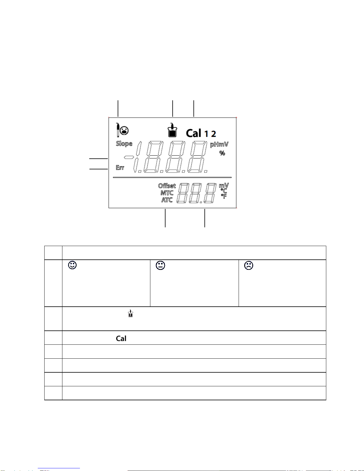
1.2 Display and controls....................................................................... 3
2Installation............................................................................5
2.1 Package contents............................................................................ 5
2.2 Installing the built-in electrode arm .............................................. 6
2.3 Installing power adapter................................................................. 6
2.4 Installing the electrodes................................................................. 7
3STARTER 2100 operation....................................................8
3.1 Calibration........................................................................................ 8
3.1.1 Buffer group................................................................................... 8
3.1.2 Performing 1-point calibration ....................................................... 9
3.1.3 Performing 2-point calibration....................................................... 9
3.2 Sample measurement................................................................... 10
3.2.1 pH measurement......................................................................... 10
3.2.2 mV measurement........................................................................ 10
3.3 Temperature measurement .......................................................... 10
4Setup...................................................................................10
4.1 Set MTC temperature.................................................................... 10
5Maintenance.......................................................................11
5.1 Error message................................................................................11
5.2 Meter maintenance.........................................................................11
5.3 Electrode maintenance..................................................................11
5.4 Self-diagnosis.................................................................................11
5.5 Recover factory settings .............................................................. 12
6Specifications ....................................................................13
7Buffer groups.....................................................................14


1
1 Introduction
Thank you for choosing OHAUS product.
Please read the manual completely before using the STARTER 2100 bench pH meter to avoid
incorrect operation.
STARTER 2100 has an excellent performance/price ratio and is designed for customers who want a
simple and easy-to-use bench pH meter with 0.01pH accuracy. Many accessories and optional
such as different electrodes for different applications, bottle buffer solutions are also available
from OHAUS.
You will find much helpful functionality in the meter. A few of the many existing features are:
Large liquid crystal screen with well-organized display
Electrode condition icon on the display to show the pH electrode performance
Can recall last calibration data
Quick Guide attached in the meter to help user operate
1.1 Safety measures
Measures for your protection
Never work in an environment subject to explosion hazards! The housing of
the instrument is not gas tight. (explosion hazard due to spark formation,
corrosion caused by the ingress of gases)
When using chemicals and solvents, comply with the instructions of the
producer and the general lab safety rules.
Measures for operational safety
Do not unscrew the two halves of the housing
Dry off any liquid spills immediately! The instrument is not watertight
Exclude the following environmental influences:
oPowerful vibrations
oDirect sunlight
oAtmospheric humidity greater than 80%
oCorrosive gases present
oTemperatures below 5 °C and above 40 °C
oPowerful electric or magnetic fields

2
FCC Note: This equipment has been tested and found to comply with the limits for a Class A
digital device, pursuant to part 15 of the FCC Rules. These limits are designed to provide
reasonable protection against harmful interference when the equipment is operated in a
commercial environment. This equipment generates, uses, and can radiate radio frequency
energy and, if not installed and used in accordance with the instruction manual, may cause
harmful interference to radio communications. Operation of this equipment in a residential area is
likely to cause harmful interference in which case the user will be required to correct the
interference at his own expense.

3
1.2 Display and controls
Displays
1
Electrode condition
Slope: more than 95%
and offset: ±(0-15) mV
Electrode condition is good
Slope: 90-95%
or offset: ±(15-35) mV
Electrode condition is
acceptable
Slope: less than 90%
or offset: ±(35-60) mV
Electrode condition is not
good or needs cleaning
2
Measurement icon - , measurement or calibration is running; disappear means the
reading is locked, no matter measurement
3
Calibration icon - , 1point or 2point calibration in progress
4
pH/mV reading or slope(%)in calibration
5
Error message - Err
6
Auto temperature compensation - ATC ; Manual temperature compensation - MTC
7
Temperature during measurement or Offset (mV) in calibration
2
3
1
4
6
7
5

4
Controls
Button
Press & release
Press & hold
for 3 seconds
- Start measurement or lock
current reading
- Confirm temp setting
- Start calibration
- Review the latest calibration
data (slope, offset)
- Meter turn on
- Exit, return to measurement
screen
- Meter turn off
- Entered temperature setup mode
- Increase temp. value when in
temp. setup mode
- Switch between pH and mV
measuring modes
- Decrease temp. value when in
temp. setup mode
- Start self-diagnosis

5
2 Installation
Carefully unpack the box.
2.1 Package contents
The model ST2100-B (basic model) has the following items:
In addition to ST2100-B content, the model ST2100-E package also includes the following:
In addition to ST2100-E content, the model ST2100-F package also includes the following:
You also could order other Ohaus pH electrodes for different applications.
Each pH buffer powder should be dissolved in 250ml pure water or deionized water in volumetric
flask. You also can order the bottle buffer solution from Ohaus.
Accessories:
Model
Description
Item NO
ST310
3-in-1 plastic refillable pH Electrode
83033965
ST210
2-in-1 plastic refillable pH Electrode
83033966
ST320
3-in-1 plastic gel pH Electrode(no need to refill)
83033967
ST230
2-in 1 glass muddy sample pH Electrode
83033968
STPURE
2-in-1 glass pure water sample pH Electrode
83033969
STTEMP30
Temperature Electrode
83033970
STORP1
Gel plastic ORP electrode
30038555
STORP2
Refillable glass ORP electrode
30038553
STREF01
Ag/AgCl reference electrode
30059253
Buffer powder set (4.01; 7.00; 10.0)
83033971
Buffer pH4.01 250ml
30065083
Buffer pH7.00 250ml
30065084
Buffer pH10.00 250ml
30065086
pH electrode Reference Electrolyte
30059255
ST2100-B
Units
STARTER 2100
1
Built-in electrode arm
1
12V Power supply
1 set
ST210 2-in-1 pH electrode
1
pH Buffer Power Set (4.01, 7.00, 10.01)
1 set
STTEMP30 temperature electrode
1

6
pH electrode protection solution
30059256
pH sensor protect bottle(10 in bag)
30064800
Electrode holder attached (2100)
30058732
Electrode holder stand alone (3100/3100C)
30058733
2.2 Installing the built-in electrode arm
Install the built-in electrode arm on the left or right sight of the STARTER 2100 meter.
Remove the arm hole rubber cover from the meter, Insert the metal stick into the hole and
screw to fasten it.
Install the upper electrode arm upon the metal stick from above; adjust it to a moderate
height.
2.3 Installing power adapter
Choose the right adapter clip, insert into the power adapter slot. Ohaus balance power supply is
also 12V which could also be used for the pH meter.

7
2.4 Installing the electrodes
Connect the pH electrode with the meter. There are 3 Socket for pH electrode. The BNC (pH),
Cinch (Temp.) and banana (REF) socket.
For ST210, we only need to connect the pH electrode with the pH socket (BNC);
For STTEMP30, connect with Temp. Socket (Cinch).
For ST310, connect both the BNC and Cinch socket.
Banana (REF) socket is only for separate Reference Electrode. (e.g. STREF01)

8
3 STARTER 2100 operation
Normally the procedure of pH measurement is the following;
a) pH electrode connect to the meter and rinsing
b) buffer preparation
c) pH electrode calibration
d) sample preparation and pH measurement
e) Measurement result record
f) pH electrode rinsing and storage
pH electrode should be rinsed with pure water before and after using. Check if the electrode is
physically damaged. (Be careful of the glass bulb which is fragile)
The pH electrode should be stored in the storage bottle.
After the pH electrode put into the sample or buffer solution, user should stir several seconds then
wait 30 to 60 seconds for the signal to be stable, and then press the button to operate (do
Calibration or measurement).
3.1 Calibration
3.1.1 Buffer group
STARTER 2100 can perform 1 or 2-point calibrations.
There are 1 buffer group (the US group) in the meter. The US buffer group is (at 25°C):
STARTER 2100 automatically corrects for the temperature dependence of the buffer pH values
given in the following table.
1.68
4.01
7.00
10.01
5°C
1.67
4.01
7.09
10.25
10 °C
1.67
4.00
7.06
10.18
15 °C
1.67
4.00
7.04
10.12
20 °C
1.68
4.00
7.02
10.06
25 °C
1.68
4.01
7.00
10.01
30 °C
1.68
4.01
6.99
9.97
35 °C
1.69
4.02
6.98
9.93
40 °C
1.69
4.03
6.97
9.89
45 °C
1.70
4.05
6.97
9.86
50 °C
1.71
4.06
6.96
9.83

9
3.1.2 Performing 1-point calibration
Calibration: pH electrode need to be calibrated with pH standard buffer solution before a proper
pH measurement. Calibration is to display the right pH value when meter receive the mV value
signal from the pH electrode.
Slope: the linear coefficient between mV and pH according to theoretical value (e.g. -
59.16mV/pH @ 25°C which means 100% slope);
Offset: the mV value when pH value is 7.00. (Theoretical value is 0 mV);
When STARTER 2100 is in pH measurement mode (see 3.2), we can do the pH electrode
calibration; place the pH electrode in a calibration buffer:
Press button-Cal, “Cal 1”displays on the top right of the screen and is blinking. Measurement
icon appear on the top of the screen, is blinking during calibration.
If the reading is stable, press button-Read to lock the reading and finish 1 point calibration.
The buffer value (e.g. pH 7.00) with the temperature display on the screen, the meter can
recognize the buffer automatically (auto buffer recognition).
The 1-point calibration is finished; now we have 3 choices to do next:
Press button-Read to store the 1-point calibration data and exit, the offset and the slope are
shown on the display for 3 seconds then return to the measurement screen.
Press button-Exit to reject the calibration, return to the measurement screen.
Press button-Cal to do the 2-point calibration.
Note: With the 1-point calibration only the offset is adjusted. If the pH electrode was previously
calibrated with multi-point calibration the previously stored slope will remain. Otherwise
theoretical 100% slope (-59.16 mV / pH @25°C) will be used.
3.1.3 Performing 2-point calibration
Perform 1-point calibration as described above.
Rinse the pH electrode with pure water and wipe off water with tissue.
Place the electrode in the next calibration buffer and press button-Cal,“Cal 2”displays on the
left bottom of the screen and “Cal ”is blinking. and appear on the top of the screen,
is blinking during calibration.
When reading is stable, press button-Read to lock the reading and finish 2-point calibration,
disappear. The buffer pH value (e.g. 7.00 pH) with the temperature display on the screen.
The 2-point calibration is finished, and then we have 2 choices to do next:
Press button-Read to store the 2-point calibration, the offset and slope are shown on the
display for 3 seconds then return to the measurement screen.
Press button-Exit to reject the calibration, return to the measurement screen.
Note: The use of a temperature electrode (e.g. STTEMP30) or a pH electrode with a built-in
temperature sensor (3-in-1 pH electrode) is recommended. If you use the MTC mode, you should
enter the correct temperature value and keep all buffer and sample solutions at the set
temperature. (See 4.1)

10
3.2 Sample measurement
3.2.1 pH measurement
Place the electrode in the sample.
Press button-Read to start the pH measurement, appears on the display. is blinking
during measurement.
When the reading is stable, press button-Read to lock the reading, disappear, the pH
value with the temperature display on the screen, you can record the measurement result. If
you want to do another measurement, press button-Read.
3.2.2 mV measurement
Press button-Mode to switch between pH measurement mode and mV measurement
mode.
Follow the same procedure as for pH measurement to perform an mV measurement.
3.3 Temperature measurement
For better accuracy, we recommend to use temperature electrode.
If a temperature electrode is used, ATC (Auto Temperature Compensation) and the sample
temperature are displayed.
If the meter does not detect a temperature electrode, it automatically switches to the Manual
Temperature Compensation mode and MTC appears. MTC temperature should be set (4.1).
Note: STARTER 2100 accepts NTC 30 kΩ temperature sensor.
4 Setup
4.1 Set MTC temperature
Press button-Temp the MTC temperature value appears on the display. Then use button-up or
button-down to increase or decrease the value to the temperature of your sample. Press button-
Read to confirm the setting then return to the measurement screen; or press button-Exit to reject
the setting and return to the measurement screen.
The default MTC temperature value setting is 25 °C (77°F).
Note: °C = 5/9 (°F -32)

11
5 Maintenance
5.1 Error message
If the measurement out of range, pH: < 0.00 or > 14.00;mV: < -1999 or > 1999; the buffer
temperature T[°C] < 5 or > 40, then the meter will display “- - -“.
If meter display “Err”, it means
Err
Self-diagnosis failure
Or Calibration failure
Repeat the self-diagnosis. (See 5.4)
Calibration failure (slope < 85%, offset > 60mV);
you need to use fresh buffer to do calibration
again properly; if still not good, need to replace
the pH electrode.
Any more problems, you can contact Ohaus sales rep or email pH@ohaus.com.
5.2 Meter maintenance
Never unscrew the two halves of the housing!
The STARTER 2100 series instruments do not require any maintenance other than occasional wipe
with a damp cloth and the replacement of depleted batteries.
The housing is made of acrylonitrile butadiene styrene (ABS). This material is attacked by some
organic solvents, such as toluene, xylene and methyl ethyl ketone (MEK). Any spillage should be
immediately wiped off.
5.3 Electrode maintenance
Make sure the electrode is filled with electrolyte solution. Always store the electrode according to
the electrode instruction manuals and do not allow it to dry out.
If the electrode response becomes sluggish or the slope is not good enough, try:
oSoak the electrode in 0.1M HCl for more than 8 hours.
oFor fat or oil contaminant, degrease the membrane with cotton wool soaked in either
acetone or a soap solution.
After electrode treatment, a new calibration should be performed. If the electrode slope is still not
good, the electrode might need to be replaced.
5.4 Self-diagnosis
Press and hold button-Read and button-Cal simultaneously until the meter display the full
screen. Each icon blinks one after the other.
This way you may check whether all icons are correctly shown. The next step is to check that the
keys are functioning correctly. This requires user interaction.

12
When bblinks, five icons are displayed.
Press the five keys in any order. Each time you press a key an icon disappears from the
screen, continue to press the other keys until all the icons have disappeared.
When the self-diagnosis has been completed successfully, appears, means “pass”. If self-
diagnosis fails, error message Err appears.
Note: You have to finish pressing all five keys within 2 minutes, otherwise Err appears and you
will have to repeat the procedure.
5.5 Recover factory settings
When the meter is off, press and hold button-Read & button-Cal & button-Exit together for 3
seconds, the screen displays and blinks, means “Reset”. Then we have 2 choice:
Press button-Read to reset factory settings (MTC, slope and offset, etc.), display
then restart the meter.
Or press button-Exit to quit the setting, display then turn off the meter.

13
6 Specifications
STARTER 2100
Measuring range
0.00…14.00 pH
–1999…1999 mV
0 °C…100 °C
Resolution
0.01 pH
1 mV
0.1 °C
Error limits
±0.01 pH
±1 mV
±0.5 °C
Calibration
1 or 2 points
1 predefined buffer group (4.01, 7.00, 10.01)
Memory
Recall last calibration data
Power supply
110-240V/50Hz, DC 12V
Size/weight
Approximately 220 W x 175 D x 78 H mm / 0.75 kg
Display
Liquid crystal
Input
BNC, impedance > 10e+12 Ω
Cinch, NTC 30 kΩ
Reference input
2mm banana socket
Temperature-compensation
ATC & MTC
Housing
ABS

14
7 Buffer groups
You can find US standard in 3.1.1, other standards for your reference.
Buffer group Europe standard
Temp℃pH2.00 pH4.01 pH7.00 pH9.21 pH11.00
5 2.02 4.01 7.09 9.45 11.72
10 2.01 4.00 7.06 9.38 11.54
15 2.00 4.00 7.04 9.32 11.36
20 2.00 4.00 7.02 9.26 11.18
25 2.00 4.01 7.00 9.21 11.00
30 1.99 4.01 6.99 9.16 10.82
35 1.99 4.02 6.98 9.11 10.64
40 1.98 4.03 6.97 9.06 10.46
45 1.98 4.04 6.97 9.03 10.28
50 1.98 4.06 6.97 8.99 10.10
Buffer group JJG119
Temp℃pH1.68 pH4.00 pH6.86 pH9.18 pH12.46
5 1.67 4.00 6.95 9.39 13.21
10 1.67 4.00 6.92 9.33 13.01
15 1.67 4.00 6.90 9.28 12.82
20 1.68 4.00 6.88 9.23 12.64
25 1.68 4.00 6.86 9.18 12.46
30 1.68 4.01 6.85 9.14 12.29
35 1.69 4.02 6.84 9.11 12.13
40 1.69 4.03 6.84 9.07 11.98
45 1.70 4.04 6.83 9.04 11.83
50 1.71 4.06 6.83 9.02 11.70
Buffer group JIS Z 8802
Temp℃pH1.68 pH4.01 pH6.86 pH9.18
5 1.67 4.00 6.95 9.40
10 1.67 4.00 6.92 9.33
15 1.67 4.00 6.90 9.28
20 1.68 4.00 6.88 9.23
25 1.68 4.01 6.86 9.18
30 1.68 4.02 6.85 9.14
35 1.69 4.02 6.84 9.10
40 1.69 4.04 6.84 9.07
45 1.70 4.05 6.83 9.04
50 1.70 4.06 6.83 9.01

Ohaus Corporation
7 Campus Drive
Suite 310
Parsippany, NJ 07054 USA
Tel: (973) 377-9000
Fax: (973) 944-7177
With offices worldwide
www.ohaus.com
PN 30031622 A© Ohaus Corporation 2013, all rights reserved
*30031622*
Other manuals for STARTER 2100
3
Table of contents
Other OHAUS Measuring Instrument manuals

OHAUS
OHAUS ST300 User manual

OHAUS
OHAUS STARTER 3100C User manual

OHAUS
OHAUS i-DT33P User manual

OHAUS
OHAUS TD52 User manual

OHAUS
OHAUS Ranger 3000 Series User manual

OHAUS
OHAUS CKW-55 User manual

OHAUS
OHAUS Defender 5000 TD52XW User manual

OHAUS
OHAUS STARTER 5000 User manual

OHAUS
OHAUS MB120 User manual

OHAUS
OHAUS TD52 User manual

OHAUS
OHAUS MB45 User manual

OHAUS
OHAUS MB90 User manual

OHAUS
OHAUS Ranger 3000 Series User manual

OHAUS
OHAUS STARTER 2100 User manual

OHAUS
OHAUS i-DT33XW User manual

OHAUS
OHAUS Defender I-D33P15B1R1 User manual

OHAUS
OHAUS STARTER 3100C User manual

OHAUS
OHAUS ST Series User manual

OHAUS
OHAUS MC2000 User manual

OHAUS
OHAUS MB120 User manual