OHAUS Defender 2200 User manual

Defender™2200 Bench Scale
Instruction Manual


Defender 2200 Bench Scale EN-1
TABLE OF CONTENTS
1. INTRODUCTION............................................................................................................... 3
1.1 Safety Precautions..................................................................................................................................3
1.2 Overview of Parts and Controls ..............................................................................................................4
1.3 Control Functions....................................................................................................................................7
2. INSTALLATION ................................................................................................................ 8
2.1 Unpacking ...............................................................................................................................................8
2.2 External Connections..............................................................................................................................8
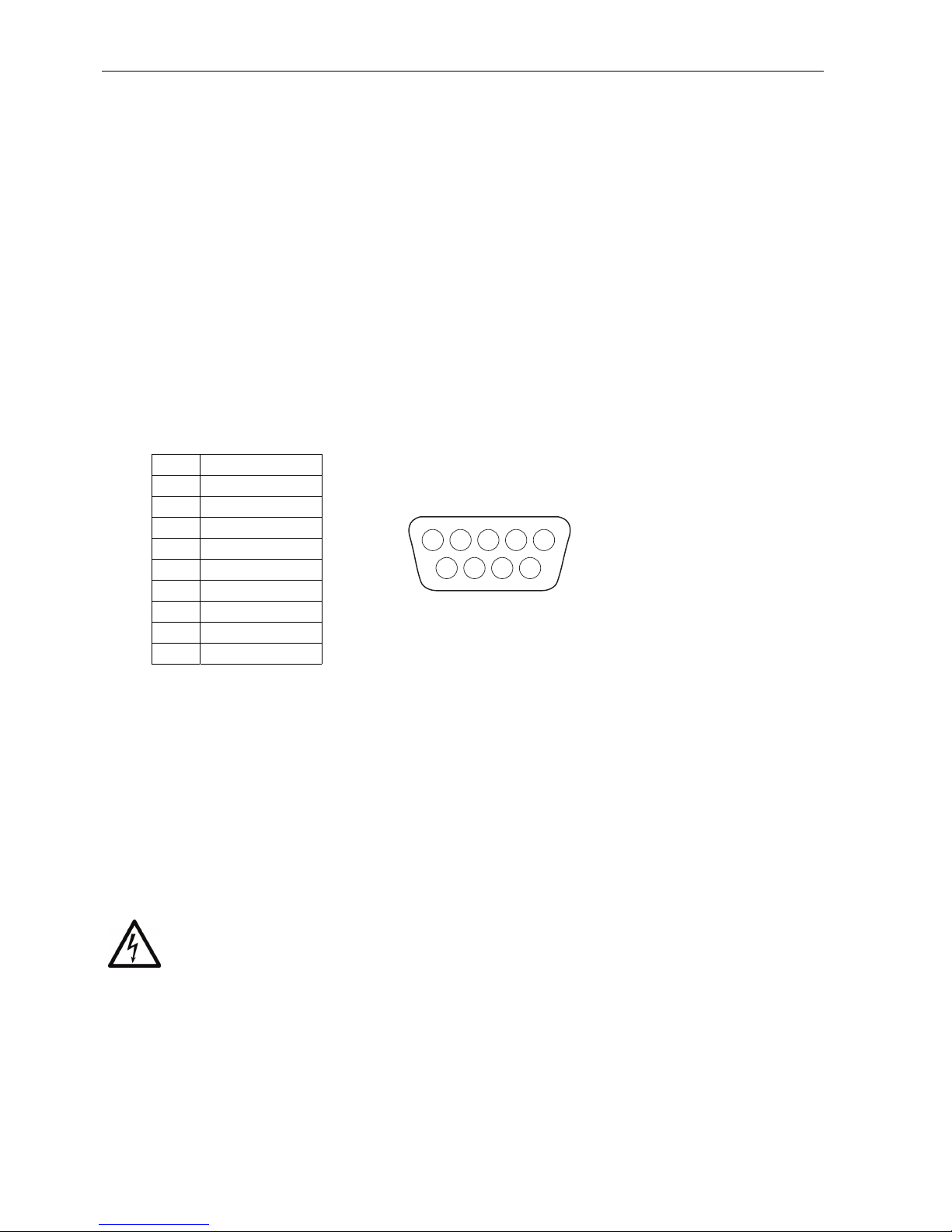
2.2.1 RS232 Inerface Cable to the Indicator ......................................................................................8
2.2.2 AC Power ..................................................................................................................................8
2.2.3 Mounting Bracket to the Indicator .............................................................................................8
2.3 Internal Connections ...............................................................................................................................8
2.3.1 Opening the Housing ................................................................................................................8
2.3.2 Scale Base to the Indicator .......................................................................................................9
2.4 Mounting the Column to the Base and Indicator ....................................................................................9
2.5 Selecting the Location...........................................................................................................................10
3. SETTINGS ...................................................................................................................... 10
3.1 Menu Structure .....................................................................................................................................10
3.2 Menu Navigation ..................................................................................................................................11
3.3 Calibration Menu...................................................................................................................................11
3.3.1 Span Calibration......................................................................................................................12
3.3.2 Linearity Calibration ................................................................................................................12
3.3.3 Geographical Adjustment Factor.............................................................................................13
3.3.4 End Calibration........................................................................................................................13
3.4 Setup Menu...........................................................................................................................................14
3.4.1 Reset .......................................................................................................................................14
3.4.2 Legal for Trade ........................................................................................................................14
3.4.3 Calibration Unit........................................................................................................................14
3.4.4 Capacity ..................................................................................................................................14
3.4.5 Graduation...............................................................................................................................15
3.4.6 Power On Unit .........................................................................................................................15
3.4.7 Zero Range .............................................................................................................................15
3.4.8 Retain Zero Data.....................................................................................................................15
3.4.9 End Setup................................................................................................................................15
3.5 Readout Menu ......................................................................................................................................18
3.5.1 Reset .......................................................................................................................................18
3.5.2 Stable ......................................................................................................................................18
3.5.3 Filter ........................................................................................................................................18
3.5.4 Auto-Zero Tracking .................................................................................................................18
3.5.5 Sleep .......................................................................................................................................19
3.5.6 Light.........................................................................................................................................19
3.5.7 Auto Off Timer .........................................................................................................................19
3.5.8 Expand Mode (for testing purposes only) ...............................................................................19
3.5.9 End Readout ...........................................................................................................................19
3.6 Mode Menu ...........................................................................................................................................20
3.6.1 Reset .......................................................................................................................................20
3.6.2 Parts Counting Mode ..............................................................................................................20
3.6.3 Display Hold Mode ..................................................................................................................20
3.6.4 Checkweigh Mode...................................................................................................................20
3.6.5 Totalize Mode..........................................................................................................................20
3.6.6 End Mode ................................................................................................................................20
3.7 Unit Menu..............................................................................................................................................21
3.7.1 Reset .......................................................................................................................................21
3.7.2 Kilogram Unit...........................................................................................................................21
3.7.3 Pound Unit...............................................................................................................................21
3.7.4 Gram Unit ................................................................................................................................21
3.7.5 Ounce Unit ..............................................................................................................................21
3.7.6 Pound Ounce Unit...................................................................................................................21
3.7.7 End Unit...................................................................................................................................21

Defender 2200 Bench ScaleEN-2
TABLE OF CONTENTS continued
3.8 Print Menu.............................................................................................................................................22
3.8.1 Reset .......................................................................................................................................22
3.8.2 Baud ........................................................................................................................................22
3.8.3 Parity .......................................................................................................................................22
3.8.4 Stop Bit....................................................................................................................................23
3.8.5 Handshake ..............................................................................................................................23
3.8.6 Print Stable Data Only.............................................................................................................23
3.8.7 Auto Print.................................................................................................................................23
3.8.8 Content....................................................................................................................................23
3.8.9 End Print..................................................................................................................................23
3.9 Lock Menu ............................................................................................................................................24
3.9.1 Reset............................................................................................................................................. 24
3.9.2 Lock Calibration.......................................................................................................................24
3.9.3 Lock Setup ..............................................................................................................................24
3.9.4 Lock Readout ..........................................................................................................................24
3.9.5 Lock Mode...............................................................................................................................24
3.9.6 Lock Unit .................................................................................................................................24
3.9.7 Lock Print ................................................................................................................................25
3.9.8 End Lock .................................................................................................................................25
3.9.9 End Menu ................................................................................................................................25
3.9.10 Security Switch........................................................................................................................25
4. OPERATION ................................................................................................................... 25
4.1 Turning Indicator On/Off .......................................................................................................................25
4.2 Zero Operation......................................................................................................................................25
4.3 Manual Tare..........................................................................................................................................25
4.4 Changing Units of Measure ..................................................................................................................26
4.5 Printing Data .........................................................................................................................................26
4.6 Application Modes.................................................................................................................................26
4.6.1 Weighing .................................................................................................................................26
4.6.2 Parts Counting.........................................................................................................................26
4.6.3 Display-Hold ............................................................................................................................28
4.6.4 Check Weighing ......................................................................................................................28
4.6.5 Totalize Weighing....................................................................................................................30
5. SERIAL COMMUNICATION ........................................................................................... 31
5.1 Interface Commands.............................................................................................................................31
5.2 Output Format.......................................................................................................................................32
6. LEGAL FOR TRADE ...................................................................................................... 33
6.1 Settings .................................................................................................................................................33
6.2 Verification ............................................................................................................................................33
6.3 Sealing ..................................................................................................................................................34
6.3.1 Physical Seals .........................................................................................................................34
6.3.2 Audit Trail Seal ........................................................................................................................35
7. MAINTENANCE.............................................................................................................. 36
7.1 Indicator Cleaning .................................................................................................................................36
7.2 Troubleshooting ....................................................................................................................................36
7.3 Service Information ...............................................................................................................................37
8. TECHNICAL DATA......................................................................................................... 38
8.1 Specifications........................................................................................................................................39
8.2 Accessories...........................................................................................................................................39
8.3 Drawings and Dimensions ....................................................................................................................39
8.3.1 Defender 2200 Indicator..........................................................................................................39
8.3.2 Defender 2200 Base ...............................................................................................................40
8.3.3 Defender 2200 Base & Indicator .............................................................................................40
8.4 Compliance ...........................................................................................................................................41

Defender 2200 Bench Scale EN-3
1. INTRODUCTION
This manual contains installation, operation and maintenance instructions for the OHAUS Defender TM 2200 Bench
Scales. Please read this manual completely before installation and operation.
1.1 Safety Precautions
For safe and dependable operation of this product, please comply with the following precautions:
•Verify that the input voltage range printed on the data label matches the local AC power.
•Make sure that the power cord does not pose a potential obstacle or tripping hazard.
•Use only approved accessories and peripherals.
•Disconnect the equipment from the power supply before cleaning.
•Operate the equipment only under ambient conditions specified in these instructions
•Ensure that the load cell cable does not pose an obstruction or tripping hazard.
•Do not operate the equipment in hazardous environments or unstable locations.
•Do not drop loads on the base.
•Do not lift the base by the top frame; always lift from the bottom frame when moving the base.
•Service should only be performed by authorized personnel.

Defender 2200 Bench ScaleEN-4
1.2 Overview of Parts and Controls
1TABLE 1-1. INDICATOR PARTS
1 Data Label
2 Front Housing
3 Adjusting Knob (2)
4 Control Panel
5 Mounting Bracket
6 Screw (4)
7 Rear Housing
8 Data Label
9 Power receptacle
10 Strain Relief for Load
Cell Cable
11 RS 232 Connector
Figure 1-1. Defender 2200 Indicator
6
7
8
9 10 11
2
3
4
5

Defender 2200 Bench Scale EN-5
1.2 Overview of Parts and Controls (Cont.)
Figure 1-2. Main PC Board
TABLE 1-2. MAIN PC BOARD
Item Description
1 Line Power Input J1
2 LFT On / Off Switch
3 RS232 Connector J3
4 Sense Jumper W2
5 Load Cell Terminal Block J7
6 Sense Jumper W1

Defender 2200 Bench ScaleEN-6
1.2 Overview of Parts and Controls (Cont.)
lb
oz
kg
Figure 1-3. Controls and Indicators T22MC
TABLE 1-3. CONTROL PANEL..
No. Designation
1 Capacity Label Window
2 Pound indicator
3 Ounce
4 Kilogram, gram indicator
5 TARE Menu button
6 CALIBRATION MODE indicator
7 FUNCTION Mode button
8 NET indicator
9 PCS indicator
10 PRINT Units button
11 Accumulation indicator
12 Hold indicator
13 ON/ZERO Off button
14 Center of Zero indicator
15 Under LED
16 Accept LED
17 Over LED
18 Stable weight indicator

Defender 2200 Bench Scale EN-7
1.3 Control Functions
TABLE 1-2. FUNCTIONS OF DISPLAY CONTROLS
Button
Primary
Function
(Short Press)
ON/ZERO
Turns the
Indicator on.
PRINT
Sends the current
value to the COM
port if AUTOPRINT
is set to Off.
FUNCTION
Initiates an
application mode.
TARE
Performs a tare
operation.
Secondary
Function
(Long Press)
Off
Turns the
Indicator off.
Units
Changes the
weighing unit.
Mode
Allows changing
the application
mode.
Press and hold
allows scrolling
through modes.
Menu
Enter the User
menu.
Extended press:
View the Audit
Trail event
counters.
Menu
Function
(Short Press)
Yes
Accepts the
current setting
on the display.
No
Advances to the
next menu or
menu item.
Rejects the current
setting on display,
advances to next
available setting.
Increments value.
Back
Moves back
to previous
menu item.
Decrements
the value.
Exit
Exits User menu.
Aborts calibration.

Defender 2200 Bench ScaleEN-8
2. INSTALLATION
2.1 Unpacking
Unpack and inspect the product to make sure that all components have been included.
The package includes the following:
• 2200 Series Indicator
• Column Assembly
• AC Adapter
• Mounting Bracket
• Knobs (2)
• Base and Weighing Pan
• Warranty Card • Instruction Manual
• LFT Sealing Kit
2.2 External Connections
2.2.1 RS232 interface Cable to the indicator
Connect the optional RS232 cable to the RS232 connector Figure 2-1).
Pin Connection
1 N/C
2 TXD
3 RXD
4 N/C
5 GND
6 N/C
7 N/C
8 N/C
9 N/C
1
2
3
4
5
6
78
9
Figure 2-1. RS232 Pins.
2.2.2 AC Power
Connect the AC Adapter to the power receptacle (Figure 1-1, item 9), then plug the AC Adapter into an electrical
outlet.
2.2.3 Mounting Bracket to the Indicator
Align the mounting bracket over the threaded holes in the side of the indicator and install the knobs.
Adjust the indicator to the desired angle and tighten the knobs.
2.3 Internal Connections
Some connections require the housing to be opened.
2.3.1 Opening the Housing
CAUTION: ELECTRICAL SHOCK HAZARD. REMOVE ALL POWER CONNECTIONS TO THE
INDICATOR BEFORE SERVICING OR MAKING INTERNAL CONNECTIONS. THE HOUSING
SHOULD ONLY BE OPENED BY AUTHORIZED AND QUALIFIED PERSONNEL, SUCH AS AN
ELECTRICAL TECHNICIAN.
Remove the four Phillips head screws from the rear housing.
Open the housing being careful not to disturb the internal connections.
Once all connections are made, reattach the front housing.

Defender 2200 Bench Scale EN-9
2.3.2 Scale Base to the indicator
Pass the load cell cable through the strain relief and attach it to terminal block J7.
Pin Connection WIRE COLOR
J7-1 +EXCITATION Green
J7-2 +SENSE Black
J7-3 +SIGNAL Red
J7-4 GROUND White
J7-5 –SIGNAL Blue
J7-6 –SENSE Brown
J7-7 –EXCITATION Yellow
Jumper Connections
For a 4-wire load cell with no sense wires: Jumpers W1 and W2 must be shorted.
For a 6-wire load cell that includes sense wires, see Figure 2-2. Jumpers W1 and W2 must be opened.
For load cells with an extra ground shield wire: Connect the shield to the center position (GND) of J7.
Figure 2-2. Jumper Connections.
After wiring is completed and jumpers are in place, replace the indicator housing screws. Make sure the strain
relief is properly tightened.
2.4 Mounting the Column to the Base and Indicator
Fasten bottom of bracket to base, thread Load Cell cable through column to indicator, fasten column to indicator
bracket. Mount bracket to indicator and install knobs as shown below.
10mm

Defender 2200 Bench ScaleEN-10
2.5 Selecting the Location
To ensure accuracy, proper performance and safety, locate and operate the base on a stable, level surface. Avoid
locations with rapid temperature changes or excessive dust, air currents, vibrations, electromagnetic fields or heat.
Level the base by adjusting the four leveling feet until the bubble in the level indicator (located at the rear of the
base) is centered. A wrench may be needed to loosen the locking nut above each leveling foot. When the base is
level, retighten the locking nuts up against the base to lock each foot into place.
Note: Ensure that the base is level each time its location is changed.
CORRECTINCORRECT
3. SETTINGS
3.1 Menu Structure
TABLE 3-1 MENU STRUCTURE
CAL (1) READOUT
AZT
OFF
0.5d
1d
3d
LINEARITY
END
END
SPAN
..
.
Y
N
Y
UNITMODE
END
END
NN
YY
RESET
YES
NO
CAPACITY
5...20000
GRADUATION
0.0005...20
CAL
UNIT
kg
lb
ZERO
RANGE
2%
100%
RESET
YES
NO
RESET YES
NO
KILOGRAM
ON
OFF
POUND
ON
OFF
GRAM
ON
OFF
OUNCE
ON
OFF
POUND:
OUNCE
ON
OFF
COUNT
ON
OFF
SETUP
END
RESET
YES
NO
LFT
OFF
ON
N
EXPAND
MODE
ON
OFF
AUTO
OFF
OFF
SET 1
SET 2
SET 5
N
GEO
00
12
19
31
Y
PRINT
AUTO
PRINT
OFF
END
NY
On Stable
Continuous
Gross
Net
Tare
Off/On
Off/On
RESET YES
NO
STABLE
ONLY
OFF
ON
Off/On
MENU LOCK
LOCK CAL
OFF
ON
END
NY
RESET YES
NO
LOCK
SETUP
OFF
ON
LOCK
READOUT
OFF
ON
LOCK
MODE
OFF
ON
LOCK UNIT
OFF
ON
LOCK
PRINT
OFF
ON
BAUD
PARITY
300
?
9600
?
19200
7EVEN
7ODD
7NoP
8NoP
Hand
Shake
OFF
XONXOFF
Unit Off/On
Power
On
UNIT
g
Kg
lb
oz
Auto
Stop
Bits
1
2
BACK
LIGHT
OFF
ON
AUTO
END
Interval
Stability
0.5d
1d
2d
3d
FILTER
LOW
MED.
HIGH
SLEEP
(T22ME)
ON
OFF
LIGHT
(T22ME)
LOW
MED.
HIGH
HOLD
ON
OFF
CHECK
WEIGH
ON
OFF
TOTAL-
IZE
ON
OFF

Defender 2200 Bench Scale EN-11
3.2 Menu Navigation
TO ENTER THE MENU MODE
Press and hold the Menu button until MENU appears on the display. The first upper level menu
appears on the display.
Summary of button navigation functions in menu mode:
Yes Allows entry into the displayed menu.
Accepts the displayed setting and advances to the next menu item.
No Skips by the displayed menu.
Rejects the displayed setting or menu item and advances to the next
available item.
Back Moves backwards through the upper and middle level menus.
Backs out of a list of selectable items to the previous middle level menu.
Exit Exits from menu directly to the active weighing mode.
For Checkweigh under and over targets setup, the current setting is displayed with all digits
flashing. Press the No button to begin editing.
The first digit is displayed flashing.
Press the No button to increment the digit or press the Yes button to accept the digit and move
to the next digit.
Repeat this process for all digits.
Press the Yes button when the last digit has been set.
The new setting is displayed with all digits flashing.
Press the Yes button to accept the setting or press the No button to resume editing.
3.3 Calibration Menu
Span
Linearity
Geographic
Adjustment
End Calibration
Perform
Perform
0…31
End CALIBRATION menu
Two calibration processes are available: Span Calibration and Linearity
Calibration.
NOTES:
1. Make sure that appropriate calibration masses are available before
beginning calibration.
2. Make sure that the scale base is level and stable during the entire
calibration process.
3. Calibration is unavailable with LFT set to On.
4. Allow the Indicator to warm up for approximately 5 minutes after
stabilizing to room temperature.
5. To abort calibration, press the Exit button anytime during the
calibration process.

Defender 2200 Bench ScaleEN-12
3.3.1 Span Calibration
Span Calibration uses two points to adjust the scale. The first point is the zero value where
there is no weight on the scale. The second point is the Span value where a calibration mass is
placed on the scale.
When SPAN is displayed, press the Yes button to access the Span Calibration menu item.
The display flashes 0. With no weight on the scale, press the Yes button to establish the zero
point.
The display shows --C-- while the zero point is established.
The display flashes the span calibration point. Place the specified weight on the scale and press
the Yes button.
To choose a different span point, repeatedly press the No button to increment the selections or
press the Back button to decrement the selections. Refer to Table 3-3 for available span points.
When the desired value is displayed, place the specified weight on the scale and press the Yes
button.
The display shows --C-- while the span point is established.
If span calibration was successful, the scale exits to the active weighing mode and displays the
actual weight value.
3.3.2 Linearity Calibration
Linearity calibration uses 3 calibration points. The first calibration point is established with no
weight on the scale. The second calibration point is established at approximately half capacity.
The third calibration point is established at capacity. The Linearity calibration points are fixed
and cannot be altered by the user during the calibration procedure. Refer to Table 3-3 for the
linearity points.
When LINEAr is displayed, press the Yes button to access the Linearity Calibration menu item.
The display flashes 0. With no weight on the scale, press the Yes button to establish the zero
point.
The display shows --C-- while the zero point is established.
The display flashes the mid calibration point.
Place the specified weight on the scale and press the Yes button.
The display shows --C-- while the mid point is established.
The display flashes the full calibration point.
Place the specified weight on the scale and press the Yes button.
The display shows --C-- while the full point is established.
If linearity calibration was successful, the scale exits to the active weighing mode and displays
the actual weight value.

Defender 2200 Bench Scale EN-13
3.3.3 Geographical Adjustment Factor
The Geographcial Adjustment Factor (GEO) is used to compensate for variations in gravity.
Settings from 0 to 31 are available. Refer to table 3-2 to determine the GEO factor that
corresponds to your location.
Note: Changing the GEO Factor alters the calibration. The GEO value was set at the factory
and should only be changed by an authorized manufacturer’s representative or certified
verirication personnel.
3.3.4 End Calibration
Advance to the next menu.

Defender 2200 Bench ScaleEN-14
TABLE 3-2. GEOGRAPHICAL ADJUSTMENT VALUES
Elevation above sea level in meters
000
325
325
650
650
975
0975
1300
1300
1625
1625
1950
1950
2275
2275
2600
2600
2925
2925
3250
3250
3575
Elevation above sea level in feet
Geographical
latitude away
from the equator
(North or South),
in degrees and
minutes.
0000
1060
1060
2130
2130
3200
3200
4260
4260
5330
5330
6400
6400
7460
7460
8530
8530
9600
09600
10660
10660
11730
0°00′- 5°46′
5°46′- 9°52′
9°52′- 12°44′
12°44′- 15°06
15°06′- 17°10′
17°10′- 19°02′
19°02′- 20°45′
20°45′- 22°22′
22°22′- 23°54′
23°54′- 25°21′
25°21′- 26°45′
26°45′- 28°06′
28°06′- 29°25′
29°25′- 30°41′
30°41′- 31°56′
31°56′- 33°09′
33°09′- 34°21′
34°21′- 35°31′
35°31′- 36°41′
36°41′- 37°50′
37°50′- 38°58′
38°58′- 40°05′
40°05′- 41°12′
41°12′- 42°19′
42°19′- 43°26′
43°26′- 44°32′
44°32′- 45°38′
45°38′- 46°45′
46°45′- 47°51′
47°51′- 48°58′
48°58′- 50°06′
50°06′- 51°13′
51°13′- 52°22′
52°22′- 53°31′
53°31′- 54°41′
54°41′- 55°52′
55°52′- 57°04′
57°04′- 58°17′
58°17′- 59°32′
59°32′- 60°49′
60°49′- 62°09′
62°09′- 63°30′
63°30′- 64°55′
64°55′- 66°24′
66°24′- 67°57′
67°57′- 69°35′
69°35′- 71°21′
71°21′- 73°16′
73°16′- 75°24′
75°24′- 77°52′
77°52′- 80°56′
80°56′- 85°45′
85°45′- 90°00′
05
05
06
06
07
07
08
08
09
09
10
10
11
11
12
12
13
13
14
14
15
15
16
16
17
17
18
18
19
19
20
20
21
21
22
22
23
23
24
24
25
25
26
26
27
27
28
28
29
29
30
30
31
04
05
05
06
06
07
07
08
08
09
09
10
10
11
11
12
12
13
13
14
14
15
15
16
16
17
17
18
18
19
19
20
20
21
21
22
22
23
23
24
24
25
25
26
26
27
27
28
28
29
29
30
30
04
04
05
05
06
06
07
07
08
08
09
09
10
10
11
11
12
12
13
13
14
14
15
15
16
16
17
17
18
18
19
19
20
20
21
21
22
22
23
23
24
24
25
25
26
26
27
27
28
28
29
29
30
03
04
04
05
05
06
06
07
07
08
08
09
09
10
10
11
11
12
12
13
13
14
14
15
15
16
16
17
17
18
18
19
19
20
20
21
21
22
22
23
23
24
24
25
25
26
26
27
27
28
28
29
29
03
03
04
04
05
05
06
06
07
07
08
08
09
09
10
10
11
11
12
12
13
13
14
14
15
15
16
16
17
17
18
18
19
19
20
20
21
21
22
22
23
23
24
24
25
25
26
26
27
27
28
28
29
02
03
03
04
04
05
05
06
06
07
07
08
08
09
09
10
10
11
11
12
12
13
13
14
14
15
15
16
16
17
17
18
18
19
19
20
20
21
21
22
22
23
23
24
24
25
25
26
26
27
27
28
28
02
02
03
03
04
04
05
05
06
06
07
07
08
08
09
09
10
10
11
11
12
12
13
13
14
14
15
15
16
16
17
17
18
18
19
19
20
20
21
21
22
22
23
23
24
24
25
25
26
26
27
27
28
01
02
02
03
03
04
04
05
05
06
06
07
07
08
08
09
09
10
10
11
11
12
12
13
13
14
14
15
15
16
16
17
17
18
18
19
19
20
20
21
21
22
22
23
23
24
24
25
25
26
26
27
27
01
01
02
02
03
03
04
04
05
05
06
06
07
07
08
08
09
09
10
10
11
11
12
12
13
13
14
14
15
15
16
16
17
17
18
18
19
19
20
20
21
21
22
22
23
23
24
24
25
25
26
26
27
00
01
01
02
02
03
03
04
04
05
05
06
06
07
07
08
08
09
09
10
10
11
11
12
12
13
13
14
14
15
15
16
16
17
17
18
18
19
19
20
20
21
21
22
22
23
23
24
24
25
25
26
26
00
00
01
01
02
02
03
03
04
04
05
05
06
06
07
07
08
08
09
09
10
10
11
11
12
12
13
13
14
14
15
15
16
16
17
17
18
18
19
19
20
20
21
21
22
22
23
23
24
24
25
25
26

Defender 2200 Bench Scale EN-15
3.4 Setup Menu
When the Indicator is used for the first time, enter this menu to set the
Capacity and Graduation.
Reset
Legal for Trade
Calibration Unit
Capacity
Graduation
Power On Unit
Zero Range
Retain Zero Data
End Setup
No, Yes
Off, On
kg¸ lb
5…20000
0.0005…20
Auto, kg, lb, g, oz
2%, 100%
Off, On
Exit SETUP menu
3.4.1 Reset
Reset the Setup menu to the factory defaults.
No = not reset.
Yes = reset.
3.4.2 Legal for Trade
Set the legal for trade status.
OFF = off
ON = on
Turning on the “LFT” menu setting has the following effects:
• Zero-range is set and locked on “2”.
• Auto Zero Tracking is set and locked on 0.5d
• The lb:oz unit is not available as a power-on setting.
3.4.3 Calibration Unit
Set the unit during calibration.
CAL UN kg = Calibrate using kg weights
CAL UN lb = Calibrate using pound weights
3.4.4 Capacity
Set the scale capacity from 5 to 20000. Refer to the Setup Table 3.3 for available settings.

Defender 2200 Bench ScaleEN-16
TABLE 3-3. SETUP & CALIBRATION VALUES
Capacity Graduation size with LFT
OFF
Graduation size with
LFT ON Span calibration points
Linearity
calibration
points
5 0.0005, 0.001, 0.002, 0.005 0.001, 0.002, 0.005 5 2, 5
10 0.0005, 0.001, 0.002, 0.005,
0.01
0.002, 0.005, 0.01 5, 10 5, 10
15 0.001, 0.002, 0.005, 0.01 0.005, 0.01 5, 10, 15 5, 15
20 0.001, 0.002, 0.005, 0.01, 0.02 0.005, 0.01, 0.02 5, 10, 15, 20 10, 20
25 0.002, 0.005, 0.01, 0.02 0.005, 0.01, 0.02 5, 10, 15, 20, 25 10, 25
30 0.002, 0.005, 0.01, 0.02 0.005, 0.01, 0.02 5, 10, 15, 20, 25, 30 15, 30
40 0.002, 0.005, 0.01, 0.02 0.01, 0.02 5, 10, 15, 20, 25, 30, 40 20, 40
50 0.005, 0.01, 0.02, 0.05 0.01, 0.02, 0.05 5, 10, 15, 20, 25, 30, 40, 50 25, 50
60 0.005, 0.01, 0.02, 0.05 0.01, 0.02, 0.05 5, 10, 15, 20, 25, 30, 40, 50, 60 30, 60
75 0.005, 0.01, 0.02, 0.05 0.02, 0.05 5, 10, 15, 20, 25, 30, 40, 50, 60, 75 30, 75
100 0.005, 0.01, 0.02, 0.05, 0.1 0.02, 0.05, 0.1 5, 10, 15, 20, 25, 30, 40, 50, 60, 75, 100 50, 100
120 0.01, 0.02, 0.05, 0.1 0.02, 0.05, 0.1 5, 10, 15, 20, 25, 30, 40, 50, 60, 75, 100, 120 60, 120
150 0.01, 0.02, 0.05, 0.1 0.05, 0.1 5, 10, 15, 20, 25, 30, 40, 50, 60, 75, 100, 120, 150 75, 150
200 0.01, 0.02, 0.05, 0.1, 0.2 0.05, 0.1, 0.2 5, 10, 15, 20, 25, 30, 40, 50, 60, 75, 100, 120, 150, 200 100, 200
250 0.05, 0.1, 0.2 0.05, 0.1, 0.2 5, 10, 15, 20, 25, 30, 40, 50, 60, 75, 100, 120, 150, 200, 250 120, 250
300 0.02, 0.05, 0.1, 0.2 0.05, 0.1, 0.2 5, 10, 15, 20, 25, 30, 40, 50, 60, 75, 100, 120, 150, 200, 250, 300 150, 300
400 0.02, 0.05, 0.1, 0.2 0.1, 0.2 5, 10, 15, 20, 25, 30, 40, 50, 60, 75, 100, 120, 150, 200, 250, 300,
400
200, 400
500 0.05, 0.1, 0.2, 0.5 0.1, 0.2, 0.5 5, 10, 15, 20, 25, 30, 40, 50, 60, 75, 100, 120, 150, 200, 250, 300,
400, 500
250, 500
600 0.05, 0.1, 0.2, 0.5 0.1, 0.2, 0.5 5, 10, 15, 20, 25, 30, 40, 50, 60, 75, 100, 120, 150, 200, 250, 300,
400, 500, 600
300, 600
750 0.05, 0.1, 0.2, 0.5 0.2, 0.5 5, 10, 15, 20, 25, 30, 40, 50, 60, 75, 100, 120, 150, 200, 250, 300,
400, 500, 600, 750
300, 750
1000 0.05, 0.1, 0.2, 0.5, 1 0.2, 0.5, 1 5, 10, 15, 20, 25, 30, 40, 50, 60, 75, 100, 120, 150, 200, 250, 300,
400, 500, 600, 750, 1000
500, 1000
1200 0.1, 0.2, 0.5, 1 0.2, 0.5, 1 5, 10, 15, 20, 25, 30, 40, 50, 60, 75, 100, 120, 150, 200, 250, 300,
400, 500, 600, 750, 1000, 1200
600, 1200
1500 0.1, 0.2, 0.5, 1 0.5, 1 5, 10, 15, 20, 25, 30, 40, 50, 60, 75, 100, 120, 150, 200, 250, 300,
400, 500, 600, 750, 1000, 1200, 1500
750, 1500
2000 0.1, 0.2, 0.5, 1, 2 0.5, 1, 2 5, 10, 15, 20, 25, 30, 40, 50, 60, 75, 100, 120, 150, 200, 250, 300,
400, 500, 600, 750, 1000, 1200, 1500, 2000
1000, 2000
2500 0.2, 0.5, 1, 2 0.5, 1, 2 5, 10, 15, 20, 25, 30, 40, 50, 60, 75, 100, 120, 150, 200, 250, 300,
400, 500, 600, 750, 1000, 1200, 1500, 2000, 2500
1200, 2500
3000 0.2, 0.5, 1, 2 0.5, 1, 2 5, 10, 15, 20, 25, 30, 40, 50, 60, 75, 100, 120, 150, 200, 250, 300,
400, 500, 600, 750, 1000, 1200, 1500, 2000, 2500, 3000
1500, 3000
5000 0.5, 1, 2, 5 1, 2, 5 5, 10, 15, 20, 25, 30, 40, 50, 60, 75, 100, 120, 150, 200, 250, 300,
400, 500, 600, 750, 1000, 1200, 1500, 2000, 2500, 3000, 5000
2500, 5000
6000 0.5, 1, 2, 5 1, 2, 5 5, 10, 15, 20, 25, 30, 40, 50, 60, 75, 100, 120, 150, 200, 250, 300,
400, 500, 600, 750, 1000, 1200, 1500, 2000, 2500, 3000, 5000, 6000
2500, 5000
7500 0.5, 1, 2, 5 2, 5 5, 10, 15, 20, 25, 30, 40, 50, 60, 75, 100, 120, 150, 200, 250, 300,
400, 500, 600, 750, 1000, 1200, 1500, 2000, 2500, 3000, 5000, 6000,
7500
3000, 7500
10000 0.5, 1, 2, 5, 10 2, 5, 10 5, 10, 15, 20, 25, 30, 40, 50, 60, 75, 100, 120, 150, 200, 250, 300,
400, 500, 600, 750, 1000, 1200, 1500, 2000, 2500, 3000, 5000, 6000,
7500, 10000
5000, 10000
12000 1, 2, 5, 10, 20 2, 5, 10 5, 10, 15, 20, 25, 30, 40, 50, 60, 75, 100, 120, 150, 200, 250, 300,
400, 500, 600, 750, 1000, 1200, 1500, 2000, 2500, 3000, 5000, 6000,
7500, 10000, 12000
5000, 10000
15000 1, 2, 5, 10 5, 10 5, 10, 15, 20, 25, 30, 40, 50, 60, 75, 100, 120, 150, 200, 250, 300,
400, 500, 600, 750, 1000, 1200, 1500, 2000, 2500, 3000, 5000, 6000,
7500, 10000, 12000, 15000
7500, 15000
20000 2, 5, 10, 20 5, 10, 20 5, 10, 15, 20, 25, 30, 40, 50, 60, 75, 100, 120, 150, 200, 250, 300,
400, 500, 600, 750, 1000, 1200, 1500, 2000, 2500, 3000, 5000, 6000,
7500, 10000, 2000
10000, 20000

Defender 2200 Bench Scale EN-17
3.4.5 Graduation
Set the scale readability.
0.0005, 0.001, 0.002, 0.005, 0.01, 0.02, 0.05, 0.1, 0.2, 0.5, 1, 2, 5, 10, 20.
NOTE: Not all settings are available for each capacity. Refer to the Setup Table 3.3 for
available settings.
3.4.6 Power On Unit
Set the unit of measure displayed at startup.
Auto = last unit in use when the indicator was turned off.
Unit kg = kilograms
Unit lb = pounds
Unit g = grams
Unit oz = ounces
3.4.7 Zero Range
Set the percentage of scale capacity that may be zeroed.
0-2 = zero up to 2 percent of capacity
0-100 = zero up to full capacity
3.4.8 Retain Zero Data
Set the retain zero data status.
OFF = disabled
ON = when power is turned on, the displayed weight is based on the last
stored zero.
3.4.9 End Setup
Advance to the next menu.

Defender 2200 Bench ScaleEN-18
3.5 Readout Menu
Enter this menu to customize display functionality.
Reset
Stable
Filter Level
Auto-Zero Tracking
Sleep (T22ME)
Light (T22ME)
Backlight (T22MC)
Auto Off Timer
Expand
End Readout
No, Yes
0.5d, 1d, 2d, 3d
Lo, Med, Hi
Off, 0.5d, 1d, 3d
Off, On
Lo, Med, Hi
Off, On, Auto
Off, Set 1, Set 2, Set 5
Off, On
Exit Readout menu
3.5.1 Reset
Reset the Setup menu to the factory defaults.
No = not reset.
Yes = reset.
3.5.2 Stable
Set the amount the reading can vary while the stability symbol remains on.
0.5 d = 0.5 divisions
1 d = 1 division
2 d = 2 divisions
3 d = 3 divisions
3.5.3 Filter
Set the amount of signal filtering.
LO = less stability, faster stabilization time
MEd = normal stability, stabilization time
HI = greater stability, slower stabilization time
3.5.4 Auto-Zero Tracking
Set the automatic zero tracking functionality.
OFF = disabled.
0.5 d = the display will maintain zero until a drift of 0.5 divisions per second has
been exceeded.
1 d = the display will maintain zero until a drift of 1 division per second has been
exceeded.
3 d = the display will maintain zero until a drift of 3 divisions per second has been
exceeded.
NOTE: When the LFT menu item is set to ON, the selections are limited to 0.5d. The setting is
locked when the hardware lock switch is set to the ON position.
Table of contents
Other OHAUS Scale manuals

OHAUS
OHAUS 1200-00 User manual

OHAUS
OHAUS skx series User manual

OHAUS
OHAUS CW-11 User manual

OHAUS
OHAUS Courier 7000 User manual

OHAUS
OHAUS CF1000R User manual

OHAUS
OHAUS EXPLORER User manual

OHAUS
OHAUS valor 5000 series User manual

OHAUS
OHAUS Ranger User manual

OHAUS
OHAUS Scout pro User manual

OHAUS
OHAUS 5-0-2 User manual

OHAUS
OHAUS PR Series User manual

OHAUS
OHAUS Defender D30BR User manual

OHAUS
OHAUS BW Series User manual

OHAUS
OHAUS Explorer EX1241 User manual

OHAUS
OHAUS Scout pro User manual

OHAUS
OHAUS PX Series User manual

OHAUS
OHAUS RE-C series User manual

OHAUS
OHAUS ES6R User manual

OHAUS
OHAUS SB1200 User manual

OHAUS
OHAUS Valor 3000 User manual