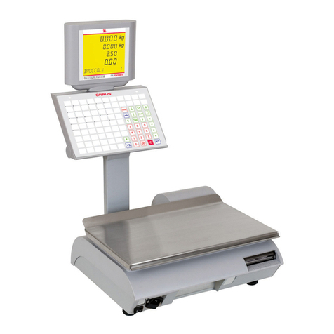
OHAUS SKIPPER 6000 Quick guide

TPLINK WIFI MODULE
INSTALLATION AND CONFIGURATION
ON SKIPPER 6000

INDEX
1. INSTALLATION WIFI MODULE IN SKIPPER 6000 SCALES............................................1
2. CONFIGURATION OF WIFI MODULE.................................................................................9
2.1. INTRODUCTION ............................................................................................9
2.2. ASPECTS TO CONSIDER.................................................................................9
2.3. MODULE DESCRIPTION.................................................................................9
2.4. DEVICE MANUAL CONFIGURATION.............................................................12
2.5. MODULE CONFIGURATION THROUGH SETTINGS FILE.................................16
3. MODULE SPECIFICATIONS................................................................................................17

SKIPPER 6000
TPLINK WIFI MODULE INSTALLATION AND CONFIGURATION
Ref: 30251574 1
1. INSTALLATION WIFI MODULE IN SKIPPER 6000 SCALES
N.
CODE DESCRIPTION QTY
1 4511013150 WIFI POWER BOARD +24v/+5v “500” TP
LINK 1
2 BCT72A WIFI MODULE + RESET 1
3 BH-P5256 ADAPT. WIFI BLACK 1
4 TO-
CL81Z31006B SCREW CL81Z 3,1x6 ZINC 2
5 TO-798504005B SCREW DIN7985 M4x5 BICHROMATED 2
6 BK-5906 ETHERNET DATA CABLE 115mm 1
7 BL-P4560 WIFI RESET STICKER 1

SKIPPER 6000
TPLINK WIFI MODULE INSTALLATION AND CONFIGURATION
Ref: 30251574 2
1. Dissasemble the plate support (allen 6 tool).
2. Dissasemble the housing (phillips screw driver).

SKIPPER 6000
TPLINK WIFI MODULE INSTALLATION AND CONFIGURATION
Ref: 30251574 3
3. Assemble the reset button.

SKIPPER 6000
TPLINK WIFI MODULE INSTALLATION AND CONFIGURATION
Ref: 30251574 4
4. Assemble wifi reset board (1) and wifi module (2) to the support (3) with 2 screws
(4). Connect the indicated cable.
5. Push the cables to let them as flat as possible.

SKIPPER 6000
TPLINK WIFI MODULE INSTALLATION AND CONFIGURATION
Ref: 30251574 5
6. Assemble the module kit with 2 screws (5). Connect the indicated cable.
7. Connect the ethernet cable from communication board to wifi module.
IMPORTANT TO CONNECT IT INTO THE RIGHT PLACE:

SKIPPER 6000
TPLINK WIFI MODULE INSTALLATION AND CONFIGURATION
Ref: 30251574 6
8. Connect the ethernet cable (6) to the CPU.
9. Connect the ethernet cable to the wifi module.

SKIPPER 6000
TPLINK WIFI MODULE INSTALLATION AND CONFIGURATION
Ref: 30251574 7
10.Place the reset sticker (8).
11.Assemble the housing.

SKIPPER 6000
TPLINK WIFI MODULE INSTALLATION AND CONFIGURATION
Ref: 30251574 8
12.Assemble the plate support. Tighten the screws with torque wrench (1,2Nm).

SKIPPER 6000
TPLINK WIFI MODULE INSTALLATION AND CONFIGURATION
Ref: 30251574 9
2. CONFIGURATION OF WIFI MODULE
2.1. Introduction
A power supply, connected to the power supply of the scale is installed together with the
module.
If you want to communicate with the scale by cable, it is necessary set the module as
Client. If the module has the standard configuration there is no connection from the
external ethernet connector and the CPU ethernet connector
2.2. Aspects to consider
The default IP address of the module is 192.168.0.254 and the subnet mask is
255.255.255.0. The PC IP address must be 192.168.0.X where X is a value
between 1 and 254.
Once a device has been configured, to configure a new one it is recommended
to erase PC ARP cache. To do thos , opend a MSDOS window and execute the
command ‘arp-d’.
If the module is configured for connection to an access point, the scale must not
be connected to the same network by cable, because it will be created a
network loop.
To communicate with the scale by cable, the module must be configured as
Client.
To make a static entry use the command "arp -s ABCD MM-MM-MM-SS-SS-SS"
where ABCD is the IP address and MM-MM-MM-SS-SS-SS is the physical
address (MAC) . This will only be necessary if IP allocation Option 3 would be
chosen.
2.3. Module description
The device which is installed in the scale is ‘TP-LINK TL-wr710N’. It is a device with
different operation modes:
Wireless router: Operate as a Router, in addition to creating a wireless network, it
is able to route between different subnets and provides Internet if you connect an
ADSL cable by its WAN port (Wide Area Network)
Access Point: Make a wireless network in which devices are connected to it. It is
not capable of routing or providing Internet access.
Repeater: Repeat the signal created by an Access Point or Router.

SKIPPER 6000
TPLINK WIFI MODULE INSTALLATION AND CONFIGURATION
Ref: 30251574 10
Client: It connects to a network created by an Access Point or Router and acts as
a Bridge. It is used to provide wireless connection to a device without wireless card.
This will be the working mode used in scales wirelesss connection.
WISP Client Router: It is like the first but with the difference that connects to the
ISP (Internet Service Provider) wirelessly and not wired.
It has 2 RJ-45 ports and acts as a switch between these 2 ports when is configured as
client. Both ports are connected to the WLAN interface (Wireless)
LAN connector - Ethernet External Connector.
Connector LAN / WAN - CPU Ethernet Connector.
Only if the device is configured as client, both RJ-45 connectors are internally
linked. So, there is access to the CPU Ethernet Connector by the external Ethernet
connector.
Other
configurations Client
configuration

SKIPPER 6000
TPLINK WIFI MODULE INSTALLATION AND CONFIGURATION
Ref: 30251574 11
IMPORTANT: If the module is configured for being connected to an access
point, never connect the scale to the same network by cable, because it will crete a
network group.
LAN-
External Ethernet
Connector
LAN/WAN-
Scale CPU

SKIPPER 6000
TPLINK WIFI MODULE INSTALLATION AND CONFIGURATION
Ref: 30251574 12
2.4. Device manual configuration
1. Connect the PC to the Scale by cable and reset the wifi module, for that hold the
reset button between 10-15 seconds.
2. Once pressed wait 60-70 seconds while the device is reset and restarted.
3. Open a browser and enter the address 192.168.0.254
4. Enter your username and password to access to device
User: admin
Password: admin.
5. The device as default is configured as ‘Wireless Router’. On the Scale, ‘Client’
operating mode will be used. To change it, we have to access the menu "Working
Mode", select the option ‘Client’ and click ‘Save’.
A window will be shown to accept the change. Click on apply.
6. The module will restart and the changes will be applied automatically. When the
device is ready again, the menu will change, since there are options that are not
applicable in client mode.
7. To set to which network should be connected (SSID), enter to the menu
"Wireless-> Wireless Settings"
WIFINetwork

SKIPPER 6000
TPLINK WIFI MODULE INSTALLATION AND CONFIGURATION
Ref: 30251574 13
Set the values of SSID, Access Point MAC and region.
Wireless Name of Root AP (SSID): Type the name of the wireless network.
MAC Address of Root AP (BSSID): Type the value of the Access Point MAC
address.
It is not obligatory, just enter a valid value.
Region: Select the country.
Click Save, wait until the changes be applied.
8. The next step is configured the security, for that go to the menu “Wireless-
>Wireless Security”.
Choose the encryption type to use and configuration of it.
Example:
Version: WPA-PSK
Encryption: TKIP
Wireless Password: Password to use
Click Save, wait until the changes be applied.
9. LAN interface configuration. The wifi module has its own IP, which does not
necessarily have to be in the scale IP range, it is only to access to the module, to
configure or view the status.
There are three options to IP assignment:
Static: The IP is assigned manually. If this method is used, it can maintain a
correlation between scale IP address and the module. Example: If the scale has
the IP 172.23.227.150, the module can be set with the address 192.168.0.150.
Advantage: you can always know the IP module without consulting the DHCP
server
Drawback: Requires configure IPs one by one.
Dynamic: The IP address is assigned automatically by a DHCP server thus, to
access to the module, you have to view your IP through the own DHCP server.
Advantage: all modules have the same configuration. Therefore it is only
necessary to load the configuration file.
WIFIPASSWORD

SKIPPER 6000
TPLINK WIFI MODULE INSTALLATION AND CONFIGURATION
Ref: 30251574 14
Drawback: To know your IP you must consult the DHCP server and know the
MAC of each device.
Static and leave default: Consist in not change the default IP.
Advantage: You can always know the module IP without consulting the DHCP
server.
Drawback: all modules have the same IP so it can not be chosen to which
module we access unless a static ARP entry is made.
The menu to configure LAN interface is in “Network->LAN”
Type: It is possible choose between static IP or Smart IP(Dynamic)
IP Address: Device IP. Default 192.168.0.254
Subnet mask: Subnet mask.
IGMP Proxy: Select the option “Disable”.
Click “Save” and the device will apply the new LAN interface configuration.
10. If static IP is selected, DHCP server operation mode should be disabled. To do
that, go to the menu “DHCP->DHCP Settings”, select the option “disable” and
click “Save”

SKIPPER 6000
TPLINK WIFI MODULE INSTALLATION AND CONFIGURATION
Ref: 30251574 15
A message is shown below indicating that you must restart device to apply changes. Click
on the link for it (Click here)
11. Create a configuration file
It can be generated a configuration file to apply this configuration to other modules
without doing all steps.
When configuration is done select the menu “System Tools->Backup & Restore” and
click “Backup”.

SKIPPER 6000
TPLINK WIFI MODULE INSTALLATION AND CONFIGURATION
Ref: 30251574 16
A file with settings is created. The default name is ‘Config.bin’ but it can be renamed.
2.5. Module configuration through settings file
Is possible configure the module with all parameters loading a settings file.
Follow next steps:
1. Reset the module.
2. Wait until the module will reset and restart
3. Open a browser and go to address 192.168.0.254
4. Enter user and password to access to module.
5. From the main menu select “System Tools->Backup & Restore” and choose the
option select settings file.
When the file is selected click “Restore” and then in the window that it will be shown, click
OK.
The device will apply changes and will restart it automatically.
6. Wait 60-70 seconds until the module be available again. Then check that the
configuration is loaded correctly in the ‘Status’ menu.
7. If it is required that the IP be static and different in each module, go to menu
“Network->LAN” change the IP and click on “Save”.

SKIPPER 6000
TPLINK WIFI MODULE INSTALLATION AND CONFIGURATION
Ref: 30251574 17
3. MODULE SPECIFICATIONS
HARDWARE FEATURES
Interface 1 10/100Mbps WAN/LAN Port, 1 10/100Mbps LAN Port
1 USB Port
1 Reset Button
Dimensions (W X D X H) 3.3 x 3.0 x 1.1 in. (85 x 75 x28 mm)
Wireless Standards IEEE 802.11n, IEEE 802.11g, IEEE 802.11b
Antenna Type On-Board
WIRELESS FEATURES
Frequency 2.4-2.4835GHz
Signal Rate 11n: Up to 150Mbps(dynamic)
11g: Up to 54Mbps(dynamic)
11b: Up to 11Mbps(dynamic)
Reception Sensitivity 135M:-70dBm@10%PER
65M:-73dBm@10%PER
54M:-76dBm@10%PER
Transmit Power
CE:
<20dBm(2.4GHz)
FCC:
<30dBm
Wireless Modes Router, Access Point, Client, WISP, Repeater
Wireless Functions Enable/Disable Wireless Radio, WDS Bridge,
WMM,Wireless Statistics
Wireless Security 64/128/152-bit WEP, WPA/WPA2, WPA-PSK/WPA2-
PSK

SKIPPER 6000
TPLINK WIFI MODULE INSTALLATION AND CONFIGURATION
Ref: 30251574 18
SOFTWARE FEATURES
WAN Type Dynamic IP/Static IP/PPPoE/PPTP/L2TP
DHCP Server, Client, DHCP Client List,Address Reservation
Quality of
Service WMM, Bandwidth Control
Port
Forwarding Virtual Server, Port Triggering, UPnP, DMZ
Dynamic
DNS DynDns, Comexe, NO-IP
VPN Pass-
Through PPTP, L2TP, IPSec (ESP Head)
Access
Control Local Management Control, Host List, Access Schedule, Rule Management
Firewall
Security
DoS, SPI Firewall
IP Address Filter/MAC Address Filter/Domain Filter
IP and MAC Address Binding
Management Access Control
Local Management
Remote Management
OTHERS
Certification CE, FCC, RoHS
Package
Contents
TL-WR710N
Ethernet Cable
Resource CD
Quick Installation Guide
System
Requirements Microsoft® Windows® 98SE, NT, 2000, XP, Vista™ or Windows 7, MAC®
OS, NetWare®, UNIX® or Linux.
Environment
Operating Temperature: 0~40 (32~104)
Storage Temperature: -40~70 (-40~158)
Operating Humidity: 10%~90% non-condensing
Storage Humidity: 5%~90% non-condensing
Table of contents
Other OHAUS Scale manuals

OHAUS
OHAUS ES series User manual

OHAUS
OHAUS Valor 1000 User manual

OHAUS
OHAUS Traveler User manual

OHAUS
OHAUS ranger 7000 User manual

OHAUS
OHAUS Defender D30BR User manual

OHAUS
OHAUS TP200S User manual

OHAUS
OHAUS defender 7000 User manual

OHAUS
OHAUS 1200-00 User manual

OHAUS
OHAUS VALOR 4000 User manual

OHAUS
OHAUS SD Series User manual

OHAUS
OHAUS TAJ Series User manual

OHAUS
OHAUS Valor V31XH202 User manual

OHAUS
OHAUS SD Series User manual

OHAUS
OHAUS SJX323 User manual

OHAUS
OHAUS 4000W Series User manual

OHAUS
OHAUS TAJ Carat TAJ203 User manual

OHAUS
OHAUS EXPLORER User manual

OHAUS
OHAUS Valor 1000 User manual

OHAUS
OHAUS Ranger R41ME6-M User manual

OHAUS
OHAUS DV114C User manual