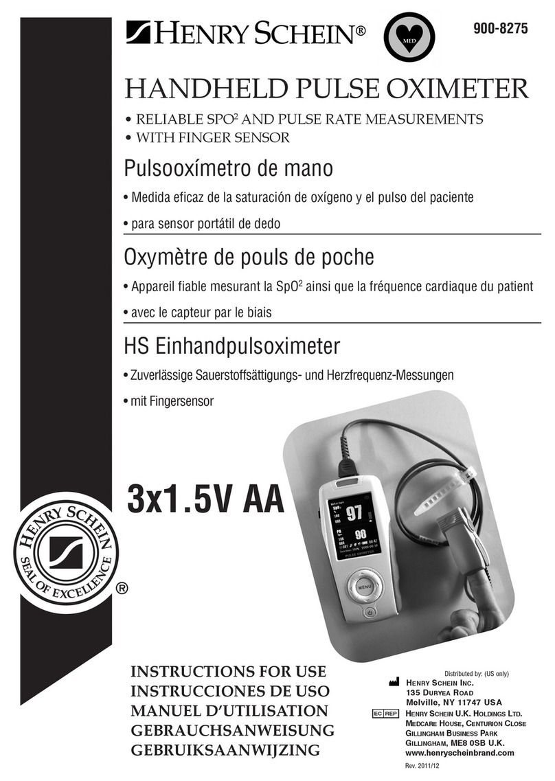
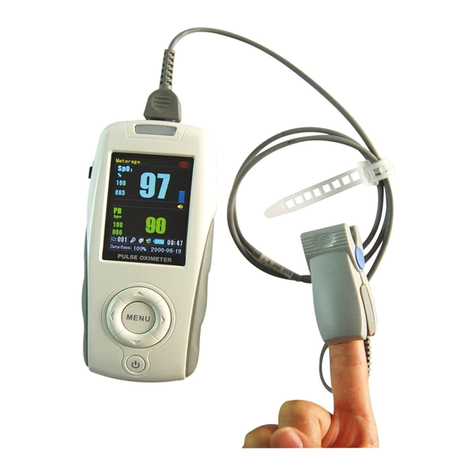
Henry Schein HS-Vet User manual


1
Statement
This manual will help you understand the operation and
maintenance of the product better. It is reminded that the product
shall be used strictly complying with this manual. User’s operation
failing to comply with this manual may result in malfunction or
accident for which the manufacturer can not be held liable.
The manufacturer owns the copyrights of this manual. Without
prior written consent of the manufacturer, any materials contained
in this manual shall not be photocopied, reproduced or translated
into other languages.
Materials protected by the copyright law, including but not limited
to confidential information such as technical information and
patent information are contained in this manual, the user shall not
disclose such information to any irrelevant third party.
The user shall understand that nothing in this manual grants him,
expressly or implicitly, any right or license to use any of the
intellectual properties of the manufacturer.
The manufacturer holds the rights to modify, update, and
ultimately explain this manual.
Responsibility of the Manufacturer
The manufacturer only considers itself responsible for any effect
on safety, reliability and performance of the equipment if:
Assembly operations, extensions, re-adjustments, modifications or
repairs are carried out by persons authorized by the manufacturer,
and
The electrical installation of the relevant room complies with
national standards, and
The instrument is used in accordance with the instructions for use.
Upon request, the manufacturer may provide, with compensation,
necessary circuit diagrams, and other information to help qualified
technician to maintain and repair some parts, which the
manufacturer may define as user serviceable.
Terms Used in this Manual

2
This guide is designed to give key concepts on safety precautions.
WARNING
A WARNING label advises against certain actions or situations
that could result in personal injury or death.
CAUTION
A CAUTION label advises against actions or situations that could
damage equipment, produce inaccurate data, or invalidate a
procedure.
NOTE
A NOTE provides useful information regarding a function or a
procedure.

3
Table of Contents
1 Safety Information ............................................................6
1.1 Warnings...................................................................6
1.2 Cautions....................................................................9
1.3 Notes....................................................................... 10
1.4 Symbols in the Oximeter......................................... 12
2 Introduction..................................................................... 14
2.1 General Introduction................................................14
2.2 Panel Introduction...................................................15
2.2.1 Symbols on Screen..........................................16
2.2.2 Front Panel Buttons .........................................17
2.2.3 Rear Panel....................................................... 20
2.3 Connecting Sensor or Cable................................... 20
2.4 Powered by Battery................................................. 21
2.5 Accessory List.........................................................24
3 Oximeter Operation........................................................26
3.1 Turning on the Oximeter..........................................26
3.2 Measurement State.................................................26
3.2.1 Measurement Modes .......................................26
3.2.2 Trend Graph and Trend Table..........................27
3.2.3 Abnormal Measurement State..........................28
3.2.4 Data Transfer State.......................................... 28
3.3 System Menu ..........................................................29
3.3.1 System Mode................................................... 31
3.3.2 Model ............................................................... 31
3.3.3 Alarm Volume...................................................31
3.3.4 Pulse Volume...................................................31
3.3.5 Audio Paused (s)..............................................32
3.3.6 User Maintain................................................... 32
3.3.7 Default Config ..................................................33
3.3.8 Alarm System...................................................34
3.3.9 SpO2 Alarm Setup........................................... 34
3.3.10 PR Alarm Setup .............................................35
3.3.11 Patient ID No. Setup ......................................36
3.3.12 Data Storage..................................................36

4
3.3.13 Delete All Data...............................................37
3.3.14 Exit (Return)...................................................38
3.4 Charging the Ni-MH Battery Package .....................38
4 Sensor Operation ...........................................................39
5 Alarm.............................................................................. 41
5.1 Alarm Categories and Levels..................................41
5.2 Alarm Conditions..................................................... 42
5.2.1 Alarm off Before the First Measurement...........42
5.2.2 Alarm for SpO2 Sensor Unconnected..............42
5.2.3 Alarm for SpO2 Sensor off...............................42
5.2.4 Alarm for Low Battery....................................... 42
5.2.5 Higher than Hi Alarm Limit............................... 43
5.2.6 Lower than Lo Alarm Limit................................43
5.2.7 Alarm Silence...................................................43
5.2.8 Turning off Alarm System.................................43
5.2.9 Alarm Priority....................................................44
6 Performance Considerations..........................................45
6.1 Performance Verification......................................... 45
6.2 Oximeter Performance Considerations ...................45
6.3 Sensor Performance Considerations.......................45
7 Maintenance................................................................... 48
8 Principles of Operation................................................... 50
8.1 Pulse Oximetry Measurement.................................50
8.2 Functional Versus Fractional Saturation.................. 51
8.3 Measured Versus Calculated Saturation.................52
9 After-Sales Service.........................................................53
AppendixⅠSpecification....................................................54
A1.1 Classification......................................................... 54
A1.2 Specification..........................................................54
A1.2.1 Size and Weight.............................................54
A1.2.2 Environment...................................................54
A1.2.3 Display...........................................................55
A1.2.4 Batteries.........................................................55
A1.2.5 Charger Stand ...............................................56

5
A1.3 Parameters...........................................................56
Appendix II EMC Information.............................................57
-Guidance and Manufacture’s Declaration ........................ 57
A2.1 Electromagnetic Emissions - for all EQUIPMENT
and SYSTEMS.............................................................. 57
A2.2 Electromagnetic Immunity - for all EQUIPMENT and
SYSTEMS.....................................................................58
A2.3 Electromagnetic emissions-for EQUIPMENT and
SYSTEMS that are not LIFE-SUPPORTING................. 59
A2.4 Recommended Separation Distances...................62
Appendix ⅢRecord Table...............................................64
Appendix ⅣAbbreviations...............................................65

6
1 Safety Information
1.1 Warnings
A WARNING label advises against certain actions or
situations that could result in personal injury or death.
WARNING
1 Avoid the explosion hazard. Do not use the Veterinary
Pulse Oximeter (hereinafter called oximeter) in the
presence of flammable Anesthetics mixture with air,
oxygen, or nitrous oxide.
2 Chemicals from a broken LCD display panel are toxic
when ingested. Use cautions when the oximeter has a
broken display panel.
3 Routinely monitor the patient to make sure the oximeter
is functioning and the sensor is correctly placed.
4 Oximetry measurements and pulse signals can be
affected by certain environmental conditions, sensor
application errors, and certain patient conditions.
5 The use of accessories, sensors, and cables other than
those specified may result in increased emission of
electromagnetic radiation and/or invalid readings of the
oximeter.
6 Do not silence the audio alarm function, or decrease the
audio alarm volume, if patient safety could be
compromised.
7 The oximeter is a prescription device to be operated
only by trained personnel. The oximeter is for attended
monitoring only.
8 The oximeter is not defibrillator-proof. However, it may
remain attached to the patient throughout defibrillation
or while an electrosurgical unit is in use. The
measurements may be inaccurate throughout the
defibrillation, or use of an electrosurgical unit, and

7
shortly thereafter. To avoid shock, the caregiver should
not hold the oximeter while using a defibrillator on a
patient.
9 Disconnect the oximeter and sensor from the patient
throughout magnetic resonance imaging (MRI) scanning.
Induced current could potentially cause burns.
10 To ensure accurate performance and prevent device
failure, do not subject the oximeter to extreme moisture,
such as direct exposure to rain. Such exposure may
cause inaccurate performance or device failure.
11 Do not lift the oximeter by the sensor or extension cable
because the cable could disconnect from the oximeter
and the oximeter may drop on the patient.
12 Do not make any clinical judgment based solely on the
oximeter. It is intended only as an adjunct in patient
assessment. It must be used in conjunction with clinical
signs and symptoms.
13 To ensure patient safety, do not place the oximeter in
any position that might cause it to fall on the patient.
14 As with all medical equipment, carefully route patient
cables to reduce the possibility of patient entanglement
or strangulation.
15 Ensure that the speaker is clear of any obstruction and
that the speaker holes are not covered. Failure to do so
could result in an inaudible alarm tone.
16 Use only sensors and extension cables permitted by the
manufacturer. Other sensors or extension cables may
be failed or cause improper monitor performance.
17 Oximeter readings and pulse signals can be affected by
certain ambient environmental conditions, sensor
application error, and certain patient conditions. See the
appropriate sections of the manual for specific safety
information.
18 Don’t mix new and old batteries together. Don’t mix
rechargeable batteries with alkaline batteries.

8
19 Periodically check the battery for corrosion. Take out the
batteries from the oximeter if you do not expect to use it
within one month.
20 The device enters POST (Power-On-Self-Test)
immediately after power-on to confirm all the display
segments and icons are shown and the speaker sounds
a few seconds tone. If you do not hear the POST pass
tone, it indicates the alarm system does not work well.
Please do not use the oximeter and contact qualified
service personnel or your local manufacturer’s
representative.
21 Before using it, the user should carefully read the
applicable user manual of sensor, including warnings,
cautions and instructions.
22 Do not use damaged sensor or extension cables, do not
use sensor with exposed optical components.
23 Tissue damage may be caused by incorrect application
or prolonged measurement duration using the sensor
(more than 2 hours). Inspect the sensor periodically
according to sensor user manual.
24 Do not immerse or wet the sensor, as this may damage
the sensor.
25 There are no user-serviceable parts inside the oximeter,
the cover should only be removed by qualified service
personnel.
26 Do not spray, pour, spill liquid to the oximeter and its
accessories, connector, switch or opening in enclosure,
as this may damage the oximeter.
27 Before cleaning the oximeter or the sensor, make sure
that the equipment is switched off and disconnected
from the power line.
28 Reusable sensors must be moved to a new site at least
every 4 hours. Because individual skin condition affects
the ability of the skin to tolerate sensor placement. It
may be necessary to change the sensor site more

9
frequently with some patients. If skin integrity changes,
move the sensor to another site.
29 Do not use supplemental tape to adhere the clip and
sensor directly to the site, this can restrict blood flow
and cause inaccurate measurements.
30 Intravascular dyes may lead to inaccurate
measurements.
31 Performance of the sensor may be compromised by
motion, particularly of a repetitive nature. If readings
cannot be obtained, try another application site.
32 Do not alter or modify the sensor. Alterations or
modifications may affect performance or accuracy.
33 Failure to apply the sensor properly may cause incorrect
measurements.
34 Using the sensor in the presence of bright lights may
result in inaccurate measurements. In such case, cover
the sensor with an opaque material.
35 This equipment is not intended for family usage.
1.2 Cautions
Cautions alert the user to exercise care necessary for the
safe and effective use of the oximeter.
CAUTION
1 All combinations of equipment must be in compliance
with IEC/EN Standard 60601-1-1 systems requirements.
2 The device and accessories are to be disposed of
according to local regulations after their useful lives.
Alternatively, they can be returned to the dealer or the
manufacturer for recycling or proper disposal. Batteries
are hazardous waste. Do NOT dispose them together
with house-hold garbage. At the end of their life hand
the batteries over to the applicable collection points for
the recycling of waste batteries. For more detailed

10
information about recycling of this product or battery,
please contact your local Civic Office, or the shop where
you purchased the product.
3 The sensor unconnected icon and associated alarm
indicate the sensor has disconnected or wire fault. So
check the sensor connection and, if necessary, replace
the sensor, extension cables or both.
4 When adjusting any menu parameters, the oximeter
does not display SpO2 or PR, but it is still recording.
5 The performance of the oximeter may degrade if the
followings occur:
— Operation or storage temperature beyond the
manufacturer’s specified range;
— Mechanical shock (for example, it drops down from
the table).
6 For the comfort of the animal and to avoid damaging the
sensor, do not pull on the cable when removing the
sensor and clip from the sensor site.
7 To remove the sensor and clip from the animal, press
the clip open and remove.
8 Federal law restricts this device to sale by or on the
order of a veterinarian.
1.3 Notes
NOTE:
Notes are identified by the symbol shown above. Notes
contain important information that may be overlooked or
missed.
NOTE:
1 This device has been tested and found to comply with
the limits for medical device in IEC/EN60601-1-2
(International standard for EMC testing of Medical
Electrical Equipment, second edition). These limits are

11
designed to provide reasonable protection against
harmful interference in a typical medical installation.
2 Sensor LED light emissions fall within Class 1 level,
according to IEC/EN 60825-1:2001. No special safety
precautions are required.
3 Normal operation means:
The oximeter is turned on;
A sensor is connected to the oximeter;
The sensor is applied to the patient;
The patient’s SpO2, Pulse rate are being
reported;
No error conditions exist.
4 Wash the probe with clean water after disinfecting it to
remove any remaining solution. The probe can only be
reused after dried thoroughly.
5 Do not disinfect the probe with the water boiled.
6 Any residue should be removed from the probe before
being disinfected, and avoid contacting corrosive
solvent. Dipping the cable into alcohol or alkalescent
solvent for a long time may reduce the flexibility of the
scarfskin of the cable. Also, the connector should not be
dipped.
7 After monitoring, disinfect the probe according to the
instruction described in the user manual.
8 The materials with which the patient or any other person
can come into contact conform with the standard of
ISO10993.
9 The pictures and interfaces in this manual are for
reference only.
10 A functional tester cannot be used to assess the
accuracy of the oximeter probe or the oximeter.
11 The operating time of the Ni-MH rechargeable battery
package depends on the configuration and operation of
the pulse oximeter.

12
1.4 Symbols in the Oximeter
This symbol indicates that the
instrument is IEC/EN 60601-1 Type BF
equipment.
Symbol for CAUTION!
Serial number
Authorized
representative in the
European community
Date of manufacture
Manufacturer
P/N Part Number
The symbol indicates that the device should
be sent to the special agencies according to
local regulations for separate collection
after its useful life.

13
Federal (U.S.) Law restric
ts this device to
sale by or on the order of a physician.
Auxiliary output connector
Recycle

14
2 Introduction
Intended Use
The Oximeter is indicated for use in measuring and displaying
functional oxygen saturation of arterial hemoglobin (SpO2) and
pulse rate (PR). It can be used for spot checking and/or continuous
monitoring of canine, feline, and equine animals when attended by
a veterinary professional.
2.1 General Introduction
The oximeter displays SpO2 value, pulse rate value,
plethysmogram, bar graph, etc.
It has been installed with the manufacturer’s SpO2module inside.
It integrates parameter module, display and recorder output
functions. It can be powered by four 1.5V AA batteries or one
Ni-MH rechargeable AA battery package. It can clearly display all
the parameter information on LCD.

15
Figure 2-1 Veterinary Pulse Oximeter
For the oximeter, Oximeter Viewer Data Management Software is
optional.
2.2 Panel Introduction
This section identifies the symbols, controls, displays, and buttons
on the front panel of the oximeter and the rear panel.

16
2.2.1 Symbols on Screen
Figure 2-2 Waveform Mode
Figure 2-3 Large Numeric Mode
Icons on the screen and their meanings:
SpO2SpO2value display area
100% Measured SpO2%
PR Pulse Rate value display area
60 bpm Measured Pulse rate (bpm)
Displays when measurement value is
higher than the upper alarm limit
Displays when measurement value is lower
than the lower alarm limit
SpO2waveform display

17
Pulse amplitude display
Low battery icon
Audio alarm off icon
Alarm off icon
Data storage icon
04: 59 Time display in Information area: “hour:
minute”
Model Model in Information area: Vet
ID: 99 ID in Information area
SpO2sensor unconnected icon
SpO2sensor off
Indicates the memory space is full
Weak signal icon
NOTE:
1 The icons for sensor unconnected, sensor off or weak
signal are displayed on the right of Information area.
Only one of them can be displayed at a time.
2 The ID icon and the icon that indicates the memory
space is full are displayed in the Information Area. Only
one icon can be displayed at a time.
2.2.2 Front Panel Buttons
This section describes the buttons on the front panel of the

18
oximeter. The controls are activated by pressing the button that
corresponds to that control. For example, press the Alarm Silence
button to control the audio alarm.
Figure 2-4 Front Panel buttons
On/Off Button
Turn on or off the oximeter.
On: Press and hold the On/Off button for one second.
Off: Press and hold the On/Off button for two seconds.
When the oximeter is off, synchronously press the On/Off button
and the Function button for one second, the oximeter will enter
Data transfer state.
In the menu state, press this button to return to the measurement
state.
Backlight Button
During the POST, the backlight is not available.
In the normal measurement, press this button to turn on or off the
backlight.
Alarm Silence Button
Alarms that occur during the POST can not be silenced.
When Alarm System in menu is setup to ON, pressing the Alarm
Silence button can turn off the audio alarm. The pause period can
be set to 30, 60, 90 or 120 seconds. Although the audio alarm is

19
off, the visual alarm is still active. After the pause period is over,
the audio alarm is reactivated.
Set Alarm System to OFF in the menu to turn off the alarm. A
Pop-up dialog box will display to confirm alarm setting. See
details in 3.3.8.
Up Arrow Button
In the menu state, press the Up Arrow button to choose different
items, and increase the value of some parameters. Press it
repeatedly to make a parameter increase by more than one. Press
and hold this button for more than one second to repeat the
increment continuously.
Press this button in measurement state to enter the latest 10-minute
SpO2or PR trend graph.
Down Arrow Button
In the menu state, pressing the Down Arrow button can choose
different items, and decrease the value of some parameters. Press
it repeatedly to make a parameter decrease by more than one.
Press and hold the button for more than one second to repeat the
decrement continuously.
Press this button in measurement state to enter the latest 10-minute
SpO2and PRtrend table.
Function Button
During the POST, the Function button is not available;
Press this button in normal measurement state to enter function
choice or setup menu;
In the menu state, this button is also used as the Enter button.
Choose one item in menu using the cursor button (the Up Arrow
button and the Down Arrow button), and press the Function
button to confirm, then increase or decrease the value using cursor
button.
When the oximeter is off, synchronously press the On/Off button
and the Function button for one second, the oximeter will enter
Data transfer state.
Table of contents
Languages:
Other Henry Schein Medical Equipment manuals

Henry Schein
Henry Schein Hydrim C61WD User manual

Henry Schein
Henry Schein Maxima 900-3510 User manual
Henry Schein
Henry Schein COLPOSCOPE I User manual
Henry Schein
Henry Schein OneStepPlus User manual

Henry Schein
Henry Schein 900-6368 User manual
Henry Schein
Henry Schein MD300K2 User manual

Henry Schein
Henry Schein COLPOSCOPE II User manual

Henry Schein
Henry Schein 900-8275 User manual
Henry Schein
Henry Schein Urispec Plus User manual