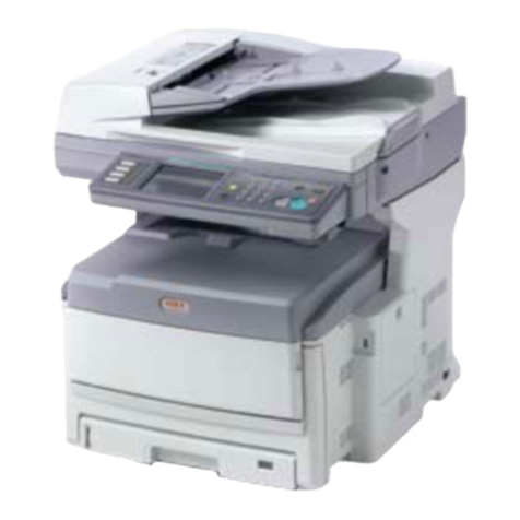
Oki S900 User manual

S900 Service Manual
031103A

S900
----------------------------------------------------------------------------------------------------------------------------------------------
ii
Contents
1. INTRODUCTION ........................................................................................................................................... 1-1
1.1 GENERAL NOTES FOR SERVICING ............................................................................................. 1-1
1.2 GENERAL DESCRIPTION .......................................................................................................... 1-2
1.3 SPECIFICATIONS...................................................................................................................... 1-2
2. UNPACKING, INSTALLATION, AND TRANSPORTATION .................................................................. 2-1
2.1 PRECAUTIONS OF INSTALLATION .............................................................................................. 2-1
2.2 UNPACKING PROCEDURE......................................................................................................... 2-1
2.3 INSTALLATION ......................................................................................................................... 2-3
2.3.1 UNLOCKING THE SCAN UNIT ........................................................................................................... 2-3
2.3.2 CONNECTING THE IEEE 1394 CABLE .............................................................................................. 2-4
2.3.3 CONNECTING THE ADF CABLE (OPTIONAL) ........................................................................................ 2-4
2.3.4 SETTING UP THE OPTIONAL ADF (AUTO DOCUMENT FEEDER) ............................................................. 2-5
2.3.5 CONNECTING THE POWER AND TURNING ON THE MACHINE ................................................................ 2-5
2.4 PLACING THE ORIGINAL ............................................................................................................ 2-6
2.4.1 PLACING YOUR DOCUMENT(S) ON THE GLASS.................................................................................... 2-6
2.4.2 PLACING DOCUMENT(S) IN THE ADF .................................................................................................. 2-7
2.5 TRANSPORTATION ................................................................................................................... 2-8
3. PARTS IDENTIFICATION............................................................................................................................ 3-1
3.1 EXTERNAL VIEW ...................................................................................................................... 3-1
3.1.1 FRONT VIEW ................................................................................................................................. 3-1
3.1.2 REAR VIEW ................................................................................................................................... 3-2
4. THEORY OF OPERATION .......................................................................................................................... 4-1
INTRODUCTION............................................................................................................................... 4-1
4.1 INTRODUCTION......................................................................................................................... 4-1
4.2 MAIN CONTROL UNIT ................................................................................................................ 4-1
4.2.1 SYSTEM DIAGRAM.......................................................................................................................... 4-2
4.2.2 MAIN CONTROL CIRCUIT ................................................................................................................. 4-3
4.2.3 VIDEO CIRCUIT: ............................................................................................................................. 4-4
4.2.4 PANEL AND LCD MODULE CIRCUIT.................................................................................................... 4-6
4.2.5 SENSOR INPUT .............................................................................................................................. 4-7
4.2.6 SUB POWER SUPPLY CIRCUIT .......................................................................................................... 4-8
4.2.7 POWER SUPPLY............................................................................................................................. 4-9
5. TROUBLESHOOTING ................................................................................................................................. 5-1
5.1 TROUBLESHOOTING FLOWCHART ............................................................................................ 5-2
5.1.1 POWER ON TO S900 READY .......................................................................................................... 5-2
5.1.2 COPY OPERATION .......................................................................................................................... 5-3
5.1.3 CONTORL PANEL OPERATION .......................................................................................................... 5-4
5.2 TABLES .................................................................................................................................. 5-5
5.2.1 LCD DOES NOT DISPLAY ................................................................................................................ 5-6
5.2.2 PRINTER DOES NOT REACT ............................................................................................................. 5-6
5.2.3 SCANNING IS NOT PERFORMED ........................................................................................................ 5-7
5.2.4 PRINTER DOES NOT PRINT ............................................................................................................... 5-7
5.2.5 IMAGE UNCLEAR ............................................................................................................................ 5-8
5.2.6 NOISE GENERATED......................................................................................................................... 5-8
5.2.7 LCD DOES NOT SHOW MESSAGE AFTER COMMAND............................................................................ 5-9
5.2.8 S900 IS NOT CONNECTED TO THE NETWORK ................................................................................. 5-10
5.2.9 ERROR CODES IN LCD ................................................................................................................ 5-11
5.3 CLEARING THE PAPER JAM .................................................................................................... 5-13
6. PREVENTIVE MAINTENANCE................................................................................................................... 6-1
6.1 CLEANING THE DOCUMENT GLASS............................................................................................ 6-1

S900
-------------------------------------------------------------------------------------------------------------------------------------------------
iii
7. DISASSEMBLY ............................................................................................................................................. 7-1
7.1 SERVICE TOOLS ...................................................................................................................... 7-1

7.2 LUBRICANTS............................................................................................................................ 7-2
7.2.1 MECHANICAL UNIT LUBRICATION ..................................................................................................... 7-2
7.3 PROCEDURE FOR DISASSEMBLY AND REASSEMBLY................................................................... 7-4
7.3.1 NOTES ON DISASSEMBLY ................................................................................................................ 7-4
7.3.2 DOCUMENT COVER......................................................................................................................... 7-4
7.3.3 CONTROL PANEL ........................................................................................................................... 7-5
7.3.4 UPPER HOUSING ............................................................................................................................ 7-6
7.3.5 DOCUMENT COVER SENSOR PCBA ................................................................................................ 7-7
7.3.6 PAPER SENSOR PCBA..................................................................................................................... 7-8
7.3.7 MAIN CONTROL BOARD ASSEMBLY.................................................................................................. 7-9
7.3.8 MOTOR BELT ............................................................................................................................... 7-10
7.3.9 OPTICAL CHASSIS......................................................................................................................... 7-11
7.3.10 CCFL INVERTER PCBA ............................................................................................................ 7-13
7.3.11 LAMP ASSEMBLY ........................................................................................................................ 7-14
7.3.12 MOTOR UNIT .............................................................................................................................. 7-15
8. PARTS............................................................................................................................................................. 8-1
8.1 SPARE PARTS LIST................................................................................................................... 8-1


S900
1-1
1. INTRODUCTION
1.1 General Notes for Servicing
1.2 General Description
1.3 Specifications
This manual is intended to be used by maintenance engineers. It describes areas to be maintained, the
detailed installation, and the component replacement procedures as well as the main trouble shooting
guides.
Please take your time to read this manual thoroughly to obtain comprehensive knowledge about the S900
before serving the unit.
1.1 GENERAL NOTES FOR SERVICING
(1) Before trying to disassemble the S900, make sure the power supply cord of the S900 is
disconnected from the power outlet. Under any circumstance, do not remove from or install the
PWBs or connectors onto the S900 with the power switch turned ON.
(2) Use caution not to drop small parts or screws inside the unit when disassembling and
reassembling. If left inside, they might cause the malfunction of the unit.
(3) Do not pull the connector cable when disconnecting it. Hold the connector.
(4) When carrying PWBs or the scanning head unit, put it in an anti-static bag.
(5) Keep the document table glass surface always clean. If contaminated, use a dry clean cloth for
cleaning.
(6) Use caution not to injure your fingers or hands when disassembling or reassembling the unit.

S900
1-2
1.2 GENERAL DESCRIPTION
The S900 provides you a fast and affordable access to color digital copying by simply connecting the
product to a color printer. This new way to make digital copies is cost effective, and it produces
dramatically better copies result than regular analog copiers. The S900 is also a high-quality scanner when
it is connected to a computer through a USB cable.
1.3 SPECIFICATIONS
General Specifications
Items Specifications
Model Type A3, Digital ScanCopier
System Features nUp to A3
nLocal copy executed by connecting to a OKI color printer
Output Quality 600 dpi, 24-bit color
Paper Size Up to A3
LCD 240*64 dot Graphic display
External Connection 1. IEEE 1394 (to connect to printer to make copies)
2. USB 2.0 (to connect to PC to scan)
3. RJ-45 (Network connection, to update printer profile and firmware)
4. ADF port (to connect to auto document feeder to copy or scan multi-page
documents)
CPU 64 MIPS CPU
Memory Size System: 128MB, Image buffer: 64 MB
ADF Capacity 50 pages
ADF Document
Weight/Thickness
14 – 28 lb. /0.002” – 0.006”
ADF Paper Feed Face Up
Flatbed Paper Feed Face Down
Power Requirement 24V DC, 2A external power adapter
Power Consumption <36 W (operating)
<24 W (standby)
<18 W (power saving)
Humidity 20% to 80%
Environment
Operation
Temperature
10°C to 35°C (50°F to 95°F)
Storage
Temperature
-10°C to 50°C (14°F to 122°F)
Dimension 589 x 502 x 318mm (23.2" x 19.75" x 12.5") (with ADF)
Weight 11.4 kg (25.1 lb) (with ADF)
MTBF 5,000 hours
MTTR 30 min
Life of Lamp 25,000 hours
Scanner Life 200,000 (flatbed) scans, or 5 years

S900
1-3
Copy Specification
Printer Language PCL
Connector Interface IEEE 1394 Cable
Copy Area 297 x 431 mm (11.19" x 16.97")
Multiple Copies Up to 99
Copy Mode Speed, FineText, Photo
Enlarge / Reduce Whole Page (93%)
25%~400% in 1% increment/decrement
Pre-set Scales
Copy Features Paper Size Auto Detection (A4 Landscape, A4
Portrait, A3)
Density Control
Copy Count up to 99
Media Type Plain Paper, Ultra-heavy, Transparency


S900
2-1
2. UNPACKING, INSTALLATION, AND
TRANSPORTATION
2.1 Precautions of Installation
2.2 Unpacking Procedure
2.3 Installation
2.4 Placing the Original
2.5 Transportation
2.1 PRECAUTIONS OF INSTALLATION
Pay attention to the following matters before unpacking and installation.
•Do not install in a place where vibration may occur.
•Keep the S900 out of direct sunlight. Do not install near a heat source.
•Do not place the S900 around materials that shut off the circulation of air.
•Do not install in a humid or dusty place.
•Use care not to scratch the glass surface of the S900 or the document holding pad with clips or
staples.
•Do not use a wall socket on the same circuit as devices that may generate noise, for example, an
air-conditioner, etc.
•Only use the DC adapter (model name ADP-50ZB made by Delta Electronics, Inc.) included with
the machine. Using other DC adapters may damage the machine and void the warranty.
•Use a suitable DC power source.
•Place the S900 on a level surface.
2.2 UNPACKING PROCEDURE
Unpack the S900 according to the following procedure.
•Remove the packing material.
•Remove the S900 from the shipping container.
•Remove the S900 from the PVC bag.
•Check the items against the following illustration.
•For any missing items, please contact the nearest dealer or distributor.
Note: Keep all the packing material in case you may need to return the S900.

S900
2-2
1. Auto Document Feeder (optional) 5. IEEE1394 cable (for printer connection)
2. S900 main unit 6. Power adapter
3. USB cable (for computer
connection)
7. Cross cable
4. CD (service tool) 8. Power Cord (US, UK, Europe, Australia)
6
5
4
3
12
78

S900
2-3
2.3 INSTALLATION
2.3.1 UNLOCKING THE SCAN UNIT
The scan unit is locked during transport to protect the scanning mechanism from being damaged. Be sure
to unlock the scan unit before using the machine.
1). Locate the lock switch at the left side of
the machine. 2). Push the lock switch down to
unlock the scan unit.
Locked Unlocked
Note:
If you need to move your S900 for repair or any other reason, be sure to lock your S900 before moving.
To lock your S900,
1. Turn off your S900.
2. If the scanning head is not located at the front of the glass, turn the S900 on to return the
scanning head to the front of the glass. After the scanning head is returned to the home position,
turn the power switch off.
3. Move the lock switch to the locked position.
The scan unit at
this position before
locking

S900
2-4
2.3.2 CONNECTING THE IEEE 1394 CABLE
1. Connect one end of the IEEE 1394 cable (included) to your printer.
2. Connect the other end to the printer port of your S900.
2.3.3 CONNECTING THE ADF CABLE (OPTIONAL)
Connect the ADF cable, which is attached to the document cover to the ADF port.

S900
2-5
2.3.4 SETTING UP THE OPTIONAL ADF (AUTO DOCUMENT FEEDER)
1. Raise the ADF Tray to about 45 degrees.
2. Pull down the wire leg beneath the ADF Tray.
3. Pull out the ADF Tray extension to its full length.
2.3.5 CONNECTING THE POWER AND TURNING ON THE MACHINE
1. Press the power switch to the “0” position to turn off your S900.
2. Connect the small end of the power cable to the power port of your S900.
3. Connect the other end to appropriate power outlet.
ADF Wire Legs
ADF Tray Extension
ADF Tray

S900
2-6
4. Press the power switch to the “I” position to turn on your S900. After showing the warming up
message, the LCD display prompts the Copy ready status.
2.4 PLACING THE ORIGINAL
You can load the paper from the S900 either in the ADF (Automatic Document Feeder) or on the glass. If
you need to copy multiple pages, please load your papers in the ADF. The ADF can hold up to 50 pages at
one time. If you need to send pages from books, newspaper clippings, paper with wrinkles or curls, please
place your paper on the glass.
2.4.1 PLACING YOUR DOCUMENT(S) ON THE GLASS
1. Open document(s) cover to reveal the glass.
2. Place your document(s) with the text FACE DOWN on the glass and align the document(s) in the
home position as shown in below.
3. Close the document cover.

S900
2-7
2.4.2 PLACING DOCUMENT(S) IN THE ADF
2.4.2.1 NOTICE ON USING THE ADF
Before using the ADF, please make sure that your paper meets the following specifications:
•Document(s) can range in size from 4.5 by 5.5 inches to 11.69 by 16.54 inches (A3).
•Document(s) can range in weight from 14 to 28 lb. (0.002” to 0.006”).
•Document(s) should be square or rectangular and in good condition (not fragile or worn).
•Document(s) should be free of curl, wrinkles, tears, wet ink, or punch holes.
•Document(s) should be free of staples, paper clips, and paper sticky notes.

S900
2-8
2.4.2.2 PLACING DOCUMENT(S) IN THE ADF
1. Make sure your document is free of staples, paper clips and is not torn out.
2. If you have multiple pages, fan your document(s) to avoid occasional paper jam. The ADF can
hold up to 50 pages at one time.
3. Place your document(s) with the text FACE UP in the ADF and make sure that the top of the
pages is fed in first.
4. Adjust the Paper Guides to center the document(s) in the ADF.
2.5 TRANSPORTATION
To move the S900 from where it is installed, for repair or any other reason, make sure to observe the
following conditions:
(1) Turn off the power of the S900.
If the scanning head is located at a place other than front of the glass, turn the S900 on to return
the scanning head to the front of the glass. After the scanning head is returned to the home
position, turn the power supply off.
(2) Move the lock switch to the locked position.
(3) Remove the power and printer cables.
(4) Put the S900 in the packing case with the packing material.

S900
3-1
3. PARTS IDENTIFICATION
3.1 External View
3.1 EXTERNAL VIEW
3.1.1 FRONT VIEW
1. Document Cover
2. Control Panel
1
2

S900
3-2
3.1.2 REAR VIEW
1. Printer Port
2. Service Port
3. USB Port
4. ADF Port
5. Power Jack
1 2 3 4 5

S900
4-1
4. THEORY OF OPERATION
4.1 INTRODUCTION
4.2 MAIN CONTROL UNIT
4.1 INTRODUCTION
Figure 5.1 Theory of Operation
The reflected rays of the your original as shown in the above Figure 5.1 pass through the lens and creates
an image on the CCD (Charge-Coupled Device). Then, according to the different light intensity perceived
by the CCD, the CCD will transfer these data into a series of analog signals to the CCD signal processor,
where the signals are turned into digital signals. These digital signals flow to the image processor and
store into the CPU (Central Processing Unit). Through the commands from the Control Panel, the digital
signals may go to the IEEE 1394 Controller to printer to make copies, or go to the USB controller to PC to
make scan a scan.
4.2 MAIN CONTROL UNIT
CCD
Signal
Processor 10010
Cold Cathode
Lens
CCD
Analogue
Signal Digital
Signal
Fluorescent Lamp
Image
Processor CPU
Reflected
Rays
IEEE1394
Controller
CPU
Panel / LCD
Ethernet RJ-45
Printer
Update Printer Profile
Update Firmware
Copy
USB 2.0
Controller
Scan
PC

S900
4-2
4.2.1 SYSTEM DIAGRAM
Figure 5.2 shows the system block diagram.
Figure 5.2 System block diagram
Image Processor
Main Board
Control
Section
Optical Unit
Lamp UnitInverter
Power Adapter
LCD Display &
Control Panel
24V
To Printer
CPU
ADF
IEEE 1394
Controller
RJ-45
Mac/Phy.
USB 2.0
Controller
To PC
CCD Signal
Processor
Other manuals for S900
2
Table of contents
Other Oki All In One Printer manuals