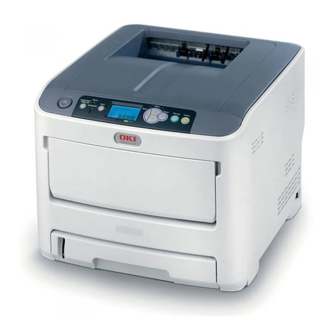
Oki C711 Series User manual

C711 / MPS711c
Maintenance Manual
020712B

Copyright Information
Copyright © 2007 by Oki Data. All Rights Reserved
Disclaimer
Every effort has been made to ensure that the information in this document is complete, accurate, and up-to-
date. The manufacturer assumes no responsibility for the results of errors beyond its control. The
manufacturer also cannot guarantee that changes in software and equipment made by other manufacturers and
referred to in this guide will not affect the applicability of the information in it. Mention of software products
manufactured by other companies does not necessarily constitute endorsement by the manufacturer.
While all reasonable efforts have been made to make this document as accurate and helpful as possible, we
make no warranty of any kind, expressed or implied, as to the accuracy or completeness of the information
contained herein.
The most up-to-date drivers and manuals are available from the web site:
http://www.okiprintingsolutions.com

44205401TH Rev.1 3 /
Oki Data CONFIDENTIAL
This manual provides an overview of method for maintaining the C711n.
This manual is intended for maintenance staff.For more information about how to operate
the C711n, please refer to User 's manual.
Note! • Manual may be revised and updated at any time without notice.
• Unexpected mistakes may exist in the manual.
OKI will not assume any responsibility whatsoever for damage to the
equipmentrepaired/adjusted/changed by the user etc with this manual.
• The parts used for this printer may be damaged when handling
inappropriately.We strongly recommend maintaining this machine by our
registration maintenance staff.
• Please operate the machine after removing static electricity.
PREFACE

44205401TH Rev.1 4 /
Oki Data CONFIDENTIAL
Index
1. Configuration...........................................................................6
1.1 System configuration............................................................................................7
1.2 The Configuration of printer..................................................................................8
1.3 Optional parts.......................................................................................................9
1.4 Specifications .....................................................................................................10
1.5 Specification of interface ....................................................................................13
1.5.1 Specification of USB interface ....................................................................13
1.5.1.1 General of USB interface.....................................................................13
1.5.1.2 Connector and cable of USB interface.................................................13
1.5.1.3 USB interface signal............................................................................13
1.5.2 Specification of network interface...............................................................14
1.5.2.1 General of network interface................................................................14
1.5.2.2 Connector and cable of network interface ...........................................14
1.5.2.3 Signal of network interface ..................................................................14
1.5.3 Specification of ACC interface ....................................................................15
1.5.4 Specification of parallel interface ................................................................16
1.5.4.1 General of parallel interface.................................................................16
1.5.4.2 Connector and cable of parallel interface ............................................16
1.5.4.3 Parallel interface level..........................................................................16
1.5.4.4 Signal of interface................................................................................16
2. Operating instructions..........................................................17
2.1 Electrophotographic processing mechanism......................................................18
2.2 Printing process..................................................................................................22
3. Set up .....................................................................................33
3.1 Notes and precautions........................................................................................34
3.2 Unpack method ..................................................................................................35
3.3 Setting method ...................................................................................................36
3.4 List of equipments and accessories ...................................................................37
3.5 Assembling method............................................................................................38
3.5.1 Assemble the main body of the printer .......................................................38
3.5.2 Cable connect.............................................................................................44
3.5.3 Optional part installation and confirmation..................................................46
3.6 Setting content print (Configuration)...................................................................57
3.7 Connecting method ............................................................................................58
3.8 User used Paper confirmation............................................................................60
4. Component replacement......................................................61
4.1 Precautions on component replacement............................................................62
4.2 Method of component replacement....................................................................64
4.2.1 Belt unit.......................................................................................................64
4.2.2 Fuser unit....................................................................................................65
4.2.3 Left side cover.............................................................................................65
4.2.4 Right side cover ..........................................................................................66
4.2.5 Faceup tray ................................................................................................66
4.2.6 Rear cover...................................................................................................67
4.2.7 LED Assy/ LED Assy spring........................................................................67
4.2.8 Control PCB................................................................................................68
4.2.9 Top cover Assy............................................................................................69
4.2.10 Top cover ....................................................................................................70
4.2.11 Control panel Assy .....................................................................................70
4.2.12 Board PRG/ LCD........................................................................................71
4.2.13 Frame panel Assy.......................................................................................72
4.2.14 Low voltage power supply/Low voltage FAN/ Hopping motor/ Fuse motor.73
4.2.15 Guide eject Assy/ Color regist Assy/ Board-PRY .......................................74
4.2.16 FAN(Fuser) / Belt motor/ High-voltage board/ Cover open switch ..............75
4.2.17 MPT Assy...................................................................................................75
4.2.18 Cover Assy front/ Board-RSF/MPT hopping roller/
Frame Assy separator/ Feeder Assy regist.................................................76
4.2.19 Board-PRZ/ Liftup motor/ Hopping motor//Paper end sensor/
Hopping sensor...........................................................................................77
4.2.20 Feed roller...................................................................................................78
4.2.21 Shaft eject Assy (FU)/ Shaft eject Assy(FD/ Eject sensor ..........................79
4.3 Oiling spots.........................................................................................................80
5. Maintenance Menu................................................................91
5.1 System maintenance menu (for maintenance engineer) ...................................92
44205401TH Rev.1 5 /
Oki Data CONFIDENTIAL
5.2 Maintenance Utilities ..........................................................................................94
5.3 Maintenance menu functions..............................................................................96
5.3.1 Self-diagnostic mode ..................................................................................96
5.3.1.1 Operation panel...................................................................................96
5.3.1.2 Ordinary self-diagnostic mode (level 1)...............................................98
5.3.1.3 Switch scan test...................................................................................99
5.3.1.4 Motor clutch test ................................................................................101
5.3.1.5 Test print............................................................................................103
5.3.1.6 Color registration correction test........................................................107
5.3.1.7 Density correction test.......................................................................108
5.3.1.8 Consumable item counter display......................................................110
5.3.1.9 Number of print copies counter display .............................................111
5.3.1.10 Switching between the Factory mode and the Shipping mode..........111
5.3.1.11 Self-diagnostic function setting..........................................................112
5.3.1.12 LED head serial number display .......................................................113
5.3.1.13 NVRAM parameter setting ................................................................113
5.3.2 Various prints with the printer as a standalone unit..................................113
5.3.3 Functions of keys at power on ..................................................................114
5.4 Setups upon completion of part replacement...................................................115
5.4.1 Precautions when replacing the CU/PU board .........................................115
5.5 Density control manual setting .........................................................................117
5.6 Printer boot menu list........................................................................................118
6. Periodic Maintenance .........................................................120
6.1 Cleaning ...........................................................................................................121
6.2 How to clean the LED lens array......................................................................122
6.3 How to clean the pickup roller ..........................................................................124
6.4 How to clean inside of printer...........................................................................125
7. Troubleshooting and repair procedure .............................127
7.1 Before starting the repair work .........................................................................128
7.2 Confirmation items before taking corrective action against abnormalities .......128
7.3 Precautions when taking corrective action against abnormality.......................128
7.4 Preparation for troubleshooting ........................................................................128
7.5 Troubleshooting method...................................................................................129
7.5.1 LCD message list......................................................................................129
7.5.2 Preparation for troubleshooting.................................................................150
7.5.3 Troubleshooting the abnormal images......................................................182
7.5.4 Network troubleshooting...........................................................................189
7.5.4.1 Connection error occurs with the Web browser.................................189
7.5.4.2 Print operation is not possible............................................................195
7.5.4.3 Cannot create Certificate...................................................................196
7.5.4.4 Installation of Certificate is not possible.............................................196
7.5.4.5 Other questionnaires .........................................................................198
7.5.4.7 Network function restrictions on Sleep mode ....................................201
7.6 Fuse check.......................................................................................................202
7.7 Paper cassette switches versus Paper size correspondence table..................203
8. Connection diagrams..........................................................204
8.1 Resistance value check....................................................................................205
8.2 Parts location....................................................................................................209
8.3 F/W version number.........................................................................................218
8.3.1 ROM control number ...................................................................................218
8.3.2 ROM version check and display ..................................................................219
8.3.3 PCB Maintenance Indication Stamp............................................................219

Oki Data CONFIDENTIAL
1.
Configuration
1.1 System configuration.....................................................................7
1.2 The Configuration of printer...........................................................8
1.3 Optional parts................................................................................9
1.4 Specifications ..............................................................................10
1.5 Specification of interface..............................................................13

44205401TH Rev.1 7 /
Oki Data CONFIDENTIAL 1.Configuration
Environmental
humidity
Feed
clutch
Hopping
clutch
Paper-feeding/
moving motor
Centronics
EEP
ROM
CD1
ASIC (1/2)
Acc
(HOST USB)
LAN USB
CU area
Option
RAM Flash
ROM
Option SD
Memory card
Paper-
feeding
clutch
MPT
clutch
Duplex
FAN Front
sensor
IN
sensor Cover
open
sensor Bottom
sensor 2nd
P.E
sensor
2nd
IN
sensor
2nd
paper
size SW
Front sensor PCB
DUPLEX PCB 2nd TRAY PCB
IN1 IN2 WR
M ID
Regist
clutch M
HOP
M
IDUP M
BELT
Duplex
clutch
Duplex
motor
1st
P.E
sensor
HOP
sensor
Belt unit
Relay PCB
Fuser
Inlet
EXIT
sensor
Density
sensor
Coler blur PCB
right
Color blur PCB
left
Belt unit
Fuse cut
Fuser fuse cut/
Upper center/ For correction/
Lower thermistor
Low-voltage PCB
FAN, heater control,
others 3.3V, 5V, 24V, 0VL, 0VP
Heater power
AC-SW
M
HEAT
ID
cooling
FAN
Low-voltage
FAN
CD1
ASIC (2/2)
PU area
Fuse cut,
EXIT Color blur, density,
thermistor signal
High-voltage I/F,
FAN control,
Cover open
EEPROM
High-voltage PCB
RFID PCB
K-ID Y-ID M-ID C-ID
Fuser
FAN Belt
thermistor
ID UP/
DOWN
Cover
open
sensor
Environment
sensor
Operation panel PCB
Toner sensor PCB
K Toner
sensor Y Toner
sensor M Toner
sensor C Toner
sensor IDfusecut
K LED HEAD
Y LED HEAD
M LED HEAD
C LED HEAD
Stacker
full
sensor
2nd
hopping
sensor
3rd
P.E
sensor
3rd
IN
sensor
3rd
paper
size SW
3rd
hopping
sensor
3rd TRAY PCB
Feed
clutch
Hopping
clutch
Paper-feeding/
moving motor
Paper
size
SW
Separator
solenoid
Fig1-1
1.1 System configuration
Figure 1-1 represents the system configuration of the printer.

44205401TH Rev.1 8 /
Oki Data CONFIDENTIAL 1.Configuration
Air flow
Fig 1-2
1.2 The Configuration of printer
The parts in the C711n are shown as below.
• Electrophotography process mechanism
• Paper feed path
• Control part (CU part/ PU part)
• Operator panel
• Power part (High-voltage part/low-voltage part)
The Configuration of the printer is shown in Fig 1-2.

44205401TH Rev.1 9 /
Oki Data CONFIDENTIAL 1. Configuration
1.3 Optional parts
The optional parts for this printer are shown as below.
(1) Optional tray(second tray/ third tray)
(2) Duplex Unit
(3) Optional memory
(4) SD memory card

44205401TH Rev.1 10 /
Oki Data CONFIDENTIAL 1. Configuration
1.4 Specifications
Division Item
Dimension Width 435mm
Depth 536mm
Height 389mm
Weight About 28kg
Width of print Width of print Letter size, vertical
Print speed Engine speed (A4) 34PPM(Color)
36PPM(Mono)
Print start First print time 8sec(mono), 9sec(color) (A4)
Warmup time 60sec
Low noise mode Not applicable
Resolution LED head 600dpi
Maximum input
resolution 600×1200dpi
Output resolution True 600×1200dpi
True 600×600dpi
Step 4 step 600×600dpi
Econo mode Save toner by recreasing brightness
CPU
Core PowerPC464
I-cash, /
D-cash L1-I=32KB
L1-D=32KB
Clock 532MHz
Bus width 32bit
RAM Resident 256MB
ROM Program+font 64MB
Division Item
Power
consumption Input power supply (120V)110~127VAC±10%,
(230V)220~240VAC±10%
Power save mode Less than 15W
Sleep mode About 0.9W (less than 1W) at AC120V
About 1W (less than 1.2W) at AC230V
Idle 100W (Average)
Usual operation 600W (It differs from operating environment)
Peak 1300W
Operating
environment
(Temperature)
During operating 10 ~32 , 17 ~27
(Temperature requirement for full-color print)
During non-
operating 0~43 , power off
During keeping
(for a year at most ) -10 ~43 , with drum and toner
During transferring
(for a month at most) -29 ~50 , with drum, without toner
During transferring
(for a month at most) -29 ~50 , with drum, without toner
Operating
environment
(Humidity)
During operating 20%~80%, 50%~70%
(Humidity requirement for full-color print)
The highest wet bulb temperature is 25
During non-
operating 10%~90%, The highest wet bulb temperature is
26.8 , power off
During keeping 10%~90%, The highest wet bulb temperature is
35
During transferring 10%~90%, The highest wet bulb temperature is
40

44205401TH Rev.1 11 /
Oki Data CONFIDENTIAL 1. Configuration
Division Item
Operation life Printer operation life 600,000 pieces A4 transvers direction, 5years
Print duty
(M=L/12, A=L/12/5) Max 60,000 pages / month
Average 6,000 pages/ month
MTBF (2.3% duty) Not applicable
MPBF 50,000 pages
MTTR Within 20 minutes
Toner operation life
(ISO/IEC19798) Mounting toner: 4,000 pages(black), 4,000
pages(color)
Standard:
11,000 pages(black), 11,500 pages(color)
For the first new drum:
about 10,200 pages(black), 10,700 pages(color)
Image drum
operation life 20,000 pages (when 3 pages /job)
12,000 pages (when 1 page/job)
27,000 pages (when continuously print)
Drum count all reset
Transcribing belt
operation life 60,000 pages (A4 transverse size, when 3 pages
/job) count auto reset
Fuser operation life 60,000 pages (A4 size) count auto reset
Operation
sound During operation 54dBA (ISO 7779 front)
(without option unit)
During standby 37dB(ISO 7779 front)
Power save mode Background level
Division Item
Paper handling
Paper stack capacity
(1st tray) Legal /Universal cassette 530 pieces (70kg)
Paper stack capacity
(optional tray) Legal /Universal cassette 530 pieces (70kg)
Paper stack capacity
(Manual/auto) Standard multipurpose tray or 100 pieces (70kg),
or 10 pieces of envelop
Paper rejection 350 pieces (70kg), facedown/
100 pieces (70kg), faceup tray
Duplex Standard/ Option
Paper size A4, A5, B5, A6*, letter, legal(13/13.5/14),
Executive, post card**, return post card**,
custom***, envelope , Index card 3x5in, Photo
size 4x6 5x7in
* : The paper of A6 cannot be used in tray 1, 2, 3
**: The post card, return post card and envelope
can be used in MPT only
***: As for custom, the available size can be
adjusted by using different tray. The length is
up to 1321mm.
Minimum paper
size Tray 1
Tray 2(option)
Tray 3(option)
MPT
A5
A5
A5
Postcard
Thickness of
paper Tray 1
Tray 2(option)
Tray 3(option)
MPT
64g/m2~220g/m2
64g/m2~220g/m2
64g/m2~220g/m2
64g/m2~250g/m2
Control panel LCD Resolution 128×64 dot graphic panel
Paper size is not displayed
LED (color) 2 (Green×1, dark umbar×1)
Switch 8

44205401TH Rev.1 12 /
Oki Data CONFIDENTIAL 1. Configuration
Division Item
Status switch/
sensor Paper out Have
Paper low None
Toner low Have (Y, M, C, K)
Cover open Have
Temperature of fuser Have
Paper size Have (Manual setting)
Stacker full Have
Communication
interface Standard
(On the PCB) • Hi-Speed USB
• Ethernet
• Centronics
Input and output
switch Auto
Emulation Standard PCL(PCL5c, HP-GL) /
PCL XL3.0
PostScript3 (Clone)
XPS
Emulation switch Auto
Font Bitmap Typeface Have
Scalable font Have
Rasterizer Have
Barcode Have
OCR Have
Japanese PCL font Have
Japanese PS font Have
Division Item
Option
(can be
removed)
RAM 256/512MB DIMM
SD memory card
It is possible to be
installed by user
16GB or 32GB SD memory card
Tray mechanism 2nd tray mechanism, 3rd tray mechanism
Cassette Universal (530 pieces)
Double print unit Standard/ Option
Others Not available
Others USB-IF logo Have
Windows logo Have
UPS operation The operation with UPS(Uninterruptible Power
Supplies) is not guaranteed.
Please do not use the UPS.

44205401TH Rev.1 13 /
Oki Data CONFIDENTIAL 1. Configuration
1.5 Specification of interface
1.5.1 Specification of USB interface
1.5.1.1 General of USB interface
(1) Spec.
USB (Support Hi speed USB )
(2) Transmission mode
Full speed (Maximum 12Mbps 0.25%)
High speed(Maximum 480Mbps 0.05%)
(3) Power control
Self power device
1.5.1.2 Connector and cable of USB interface
(1) Connector
•Printer side: B Receptacle (female)
Up-stream port
(UBR24-4K5C00 (made by ACON)) Equivalent goods
Connector pins array
(2) Cable
The length of the cable:the cable of less than 5m with USB 2.0 spec.
(Less than 2m is recommended)
(Please use the shielded wire for the cable.)
1.5.1.3 USB interface signal
Signal name Function
1 Vbus Power (+5V)
2 D- For data transmission
3 D+ For data transmission
4 GND Signal Ground
Shell Shield
• Cable side:B plug(male)
2
3 4
1

44205401TH Rev.1 14 /
Oki Data CONFIDENTIAL 1. Configuration
1.5.2 Specification of network interface
1.5.2.1 General of network interface
Spec.
Network Protocol
TCP/IP sepc. Network layer
ARP, IP, ICMP, IPv6, IPSec
Transfer layer
TCP, UDP
Application layer
LPR, Port9100, FTP, HTTP, HTTPS, IPP, SNMPv1/v3,TELENET,
DHCP/BOOTP, DNS, DDNS, WINS, UPmP, Bonjour, SNTP,
SMTP, POP,Windows Rally (WSD Print, LLTD).
NBT/NetBEUI: SMB, NetBIOS, NetBIOS over TCP
Netware: Remote printer mode(Maximum 8 print sever )
Print sever mode (Maximum 8 files sever: 32 queue)
For encrypted password (when it is print sever mode)
NetWare6J/5J/4.1J (NDS, bindery)
SNMP
EtherTalk: ELAP, AARP, DDP, AEP, NBP, ZIP, RTMP, ATP, PAP
IEEE802.1X: EAP-TLS, PEAP
(2) Cable
Non-shield twisted-pair cable with RJ-45 connector
(Category 5 is recommended)
1.5.2.3 Signal of network interface
Pin No. Signal name Direction Function
1 TXD+ FROM PRINTER Transmission data +
2 TXD- FROM PRINTER Transmission data -
3 RXD+ TO PRINTER Receive data +
4 − − Not use
5 − − Not use
6 RXD- TO PRINTER Receive data -
7 − − Not use
8 − − Not use
1 8
1.5.2.2 Connector and cable of network interface
(1) Connector
100BASE-TX/10 BASE-T (Auto switch, cannot be used simultaneously)
Connector pins array

44205401TH Rev.1 15 /
Oki Data CONFIDENTIAL 1. Configuration
1.5.3 Specification of ACC interface
1) Connector
Printer side: USB A receptacle (female)
Downstream port
DUSB-ARA42-T11A (DDK product) or equivalent
Cable side: USB A plug (male)
2) Cable
Hi-Speed USB2.0
Cable length: 2.0 m max.
(Use a shielded cable.)
Note! A cable doesn’t come with the printer.
3) Interface signals
Contact No. Signal Name Function
1 VBUS Power supply(+5V)
2 D- For data transfer
3 D+ For data transfer
4 GND Signal ground Shell
Shell Shield Shield
4) Conector pin arrengement
5) Connecting device
ODC-authorized card reader/writer
Maximum current supplied to the printer: 100 mA

44205401TH Rev.1 16 /
Oki Data CONFIDENTIAL 1. Configuration
1.5.4 Specification of parallel interface
1.5.4.1 General of parallel interface
Spec.
IEEE1284-1994 conforming parallel interface
Item Content
Related mode Compatible mode, nibble mode, and ECP mode
Data bit length Compatible:8, nibble: 4, ECP: 9bit
1.5.4.2 Connector and cable of parallel interface
(1) Connector
Printer side : 36-Pole connector (Female)
57LE-40360-12(D56) (made by DDK) equivalent goods
Cable side : 36-Pole connector (male)
57FE-30360-20N(D8) (made by DDK) equivalent goods
118
1936
Pin layout seen from interface cable side
(2) Cable
IEEE1284-1994 cable of less than 1.8m is used.
(For avoiding noise interference, please use shielded cable with the twisted-pair wire.)
1.5.4.3 Parallel interface level
Low level 0.0V~+0.8V
High level +2.4V~+5.0V
1.5.4.4 Signal of interface
Pin NO. Name of signal Direction Function
1 nStrobe (HostClk) TO PRINTER It is a pulse to read data. Data is read by
posterior end.
2~9 DATA 1~DATA 8 Bi-direction It is parallel data of 8 bits.The high level is
“1", and the Low level is “0".
10 nAck(PtrClk) FROM
PRINTER It is a signal that shows the data reception
completion.
11 Busy(PtrBusy) FROM
PRINTER It is a signal that shows if the printer is
receiving the data. Data cannot be received
when it is at the high level.
12 PError
(AckDataReq) FROM
PRINTER The paper error is shown when it is at the
high level.
13 Select(Xflag) FROM
PRINTER When parallel interface is effective, it is
always in high-level state.
14 nAutoFd(HostBusy) TO PRINTER It is used by the bidirectional communication.
15 - - Not use
16 GND - Signal ground
17 FG - Chassis ground
18 +5V FROM
PRINTER It cannot supply power outside.
19~30 GND - Signal ground
31 nInit(nInit) TO PRINTER The printer is initialized with the low level.
32 nFault(nDataAvail) FROM
PRINTER When the printer is in alarm state, it
becomes low level.
33 GND - Signal ground
34 - - Not use
35 HILEVEL FROM
PRINTER It is pulled up to +5V at 3.3K in the printer.
36 nSelectIn
(IEEE1284 active) TO PRINTER It is used by bidirectional communication.It
must be low level when it is in compatible
mode.
Notes! • The signal name showed in the bracket is a signal name in nibble mode.
• It only describes the function in compatible mode.
• The nibble mode of IEEEstd1284-1994 regulated by Institute of Electrical
and Electronics Engineers is supported. Using the computer and the
cable unsupported this standard may lead to unexpected operation.

Oki Data CONFIDENTIAL
2.
Operating instructions
2.1 Electrophotographic processing mechanism...............................18
2.2 Printing process...........................................................................22

44205401TH Rev.1 18 /
Oki Data CONFIDENTIAL 2. Operating instructions
(1) Electrophotographic processing
The general of Electrophotography process is described as below.
1. Charging
The voltage is impressed to CH roller, and the surface of OPC drum is
electrified.
2. Exposure
LED head irradiates light to the image signal on the surface of the electrified
OPC drum. The electricity of the irradiated part on the surface of the OPC drum
is attenuated by changing in light intensity, the electrostatic latent image is
formed on the surface of the OPC drum.
3. Development
The electrified toner adheres to the electrostatic latent image of the OPC drum
by electrostatic force, and the image is developed on the surface of the OPC
drum.
4. Transfer
The paper is overlapped on the surface of the OPC drum, and the electricity
is generated on the back of the paper by transfer roller, the toner image is
transcribed to the paper.
5. Fusing
Heat and pressure are applied to the toner image on the paper in order to make
it fusing.
6. Drum cleaning
The drum cleaning blade removes the toner left on the OPC drum after transfer.
7. Electricity removal
The electric potential left on the drum is removed.
8. Belt cleaning
The belt cleaning blade removes the toner left on the belt.
2.1 Electrophotographic processing mechanism
(2) Charging
The voltage is impressed to the charging roller in contact with the surface of
OPC drum, and the surface of OPC drum is charged.
(3) Exposure
The light generated from LED head is irradiated onto the surface of the electrified
OPC drum.The electricity of the irradiated part on the surface of the OPC drum is
attenuated by changing in light intensity, the electrostatic latent image is formed
on the surface of the OPC drum.
-
--
--
---
-
Power
unit
OPC drum
Paper
LED head
OPC drum
LED head
Charging roller
-
--
--
-
Power
unit
Charging roller
OPC drum

44205401TH Rev.1 19 /
Oki Data CONFIDENTIAL 2. Operating instructions
(4) Development
The toner adheres to the electrostatic latent image on the surface of the drum,
and the electrostatic latent image is changed into the toner image.
1. The sponge roller makes the toner adhere to the developing roller.
2. The electrostatic latent image on the surface of the OPC drum surface is
visualized by toner.
(5) Transfer
The paper is overlapped on the surface of the OPC drum, and the electricity is
generated on the back of the paper by transfer roller.
When high voltage is impressed from the power supply to the transfer roller, the
electricity induced in the transfer roller is moved to the surface of the paper via
contact surface, and the toner is drawn from the surface of the OPC drum to the
surface of the paper.
-
--
--
---
-
-
--
Developing roller
Sponge roller
OPC drum
Charging roller
-
--
--
---
-
-
--
--
-
+-
+-
+
-
+
-
+
-
+-
+-
+-
+-
+-
+
-
+-
+
-
+-
+
-
+-
+
Power
unit
OPC drum
Transfer roller
Paper
Transport belt

44205401TH Rev.1 20 /
Oki Data CONFIDENTIAL 2. Operating instructions
-
+-
+-
+-
+-
+
-
+
-
+-
+
-
+-
+
-
+-
+-
-
-
ID unit
Waste toner area
Toner cartridge
Drum cleaning blade
(6) Fusing
When the paper passes through the heat roller and backup roller unit, heat and
pressure are applied to the toner image on the paper and the toner is fused onto
the paper.
The halogen lamps of 800W and 400W are built in heat roller.The backup roller
without built-in halogen lamp is heated by the heat transmission from the heat
roller. The fusing temperature is controlled by the temperature detected by the
thermistor that is not in contacting with the surface of the heat roller. On the
other hand, the temperature detected by the thermistor rubbing the surface
of backup roller is used for controlling the fusing temperature under specified
conditions. Furthermore, a thermostat is used to limit the temperature rise, if
the temperature rise of heat roller exceeds a set point, the thermostat would be
open and the voltage supply to the heater would be cut off. The backup roller
unit is pressed on the heat roller by the spring on both sides.
(7) Drum cleaning
The Unfused toner left on the OPC drum is cleaned up by the drum cleaning
blade, and all residual toner is collected in the waste toner area of the toner
cartridge.
Heat roller
Backup roller
Pad
Thermistor
Thermistor
Paper
Paper feeding path
Thermostat
Fuser belt
(8) Electricity removal
The electricity on the surface of the OPC drum is attenuated by irradiating the
light to the surface of the OPC drum after transfer.
Electricity-removing
light PCB
Charging roller
OPC drum
Electricity-removing
light
Other manuals for C711 Series
1
This manual suits for next models
1
Table of contents
Other Oki Printer manuals

Oki
Oki C711dn Owner's manual

Oki
Oki MAC TECHNICAL REFERANCE C7350 User manual

Oki
Oki C6100dn User manual

Oki
Oki OKIPAGE6w Instruction sheet

Oki
Oki LP470w User manual

Oki
Oki Teriostar LP-1040-MF User manual

Oki
Oki ML3321 User manual

Oki
Oki C3300n User manual

Oki
Oki ML186 Plus User manual

Oki
Oki C7400n User manual