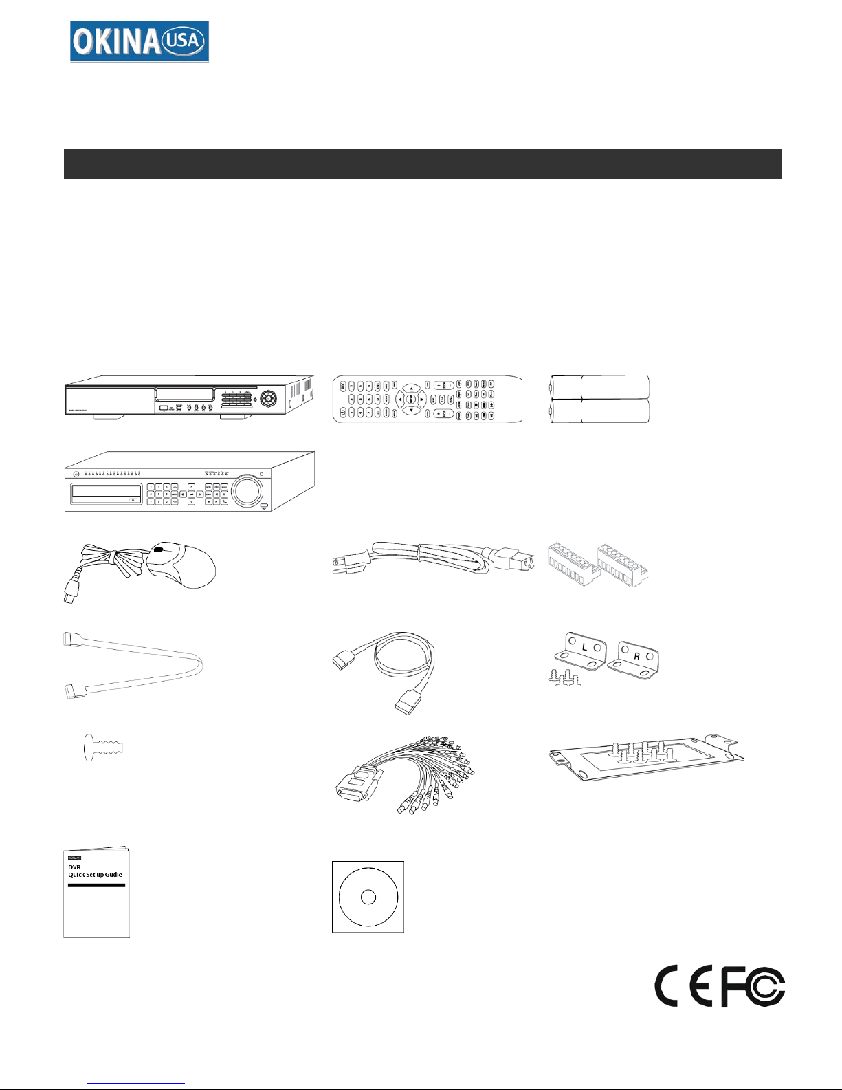
HDRR-04 / HDRR-08 / HDRR-16 Quick Setup Guide
- 6 - DV-18 / DV-19 / DV-20
R201404-V23
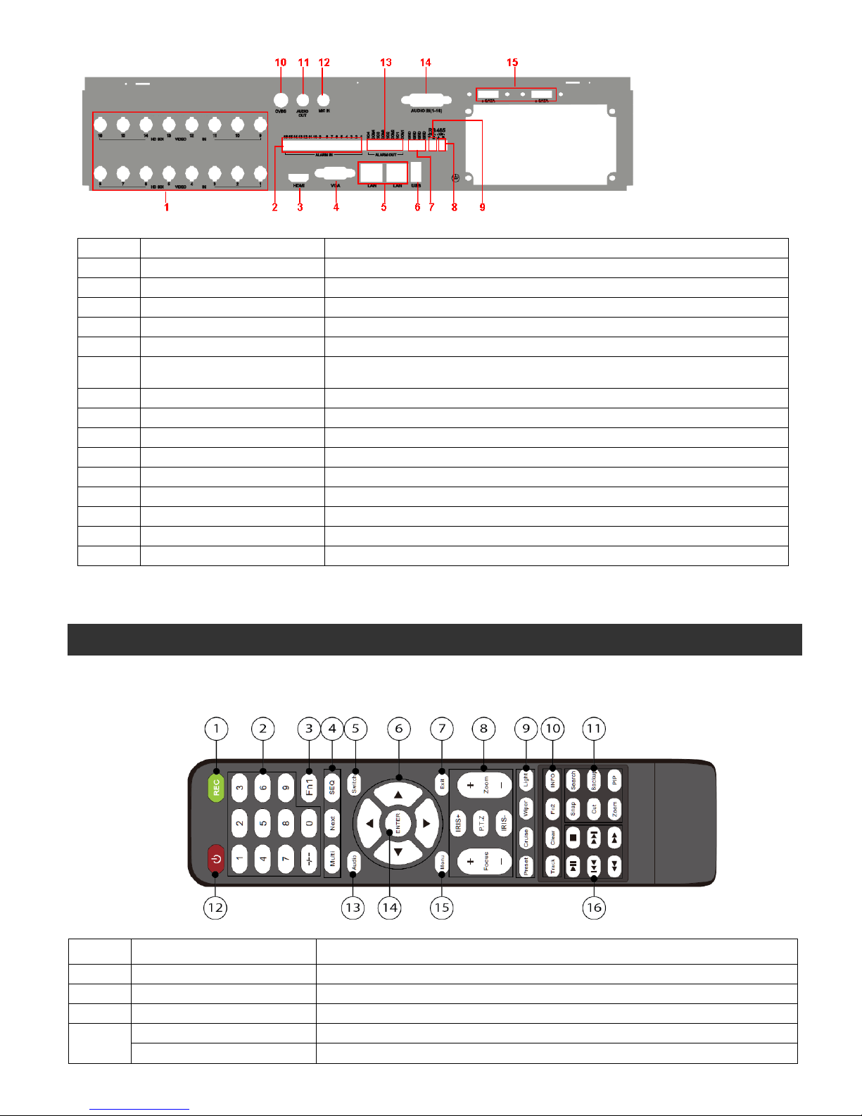
Item # Label Name Function
SEQ To enter into auto dwell mode
To switch the output between BNC and VGA
To move cursor in setup or pan/title PTZ
To exit the current interface
To control PTZ camera. Move camera/zoom/IRIS/Focus
To enter into preset setting in PTZ mode
To enter into cruise setting in PTZ mode
Wiper Button To enable wiper function in PTZ mode
Light Button To enable light function in PTZ mode
10
Track Button To enter into track setting in PTZ mode
To return to the previous interface
Get information about DVR like firmware version, HDD information
To take snapshots manually
To enter into search mode
To set the start/end time for backup in playback mode
Backup Button To enter into backup mode
Zoom Button To zoom in the images
PIP Button To enter into picture in picture setting mode
12 Power Button Switch off—to stop DVR. Use it before turning off the power
To enable audio output in live mode
To confirm the choice or setup
To control playback. Play/Pause/Stop/Previous-Section/
Next-Section/Rewind/Fast Forward
◆Switch Remote Control ID
1. Take remote control and point to DVR then continuously press “8”,”8”,”ID(0-65535)”,”Enter”.
2. Make change on DVR ID Setting,
Go to “SYSTEM MENU” > “DEVICE ID” to make change
*The ID must be the same on DVR.
*For example: If ID=1 ,
Please take remote control and point to DVR then press 8,8,1,Enter.
Then go to “SYSTEM MENU” > “DEVICE ID” change the ID=1
2.3 Mouse Control: REQUIRED
◆Connection: Recommend to connect the USB mouse to the back panel.
◆Mouse functions:
1)Under LIVE mode:
On every channel,you could double click the left button to switch FULL SCREEN and double click again
to switch back to original split mode.
On every channel,you could single click right button to popup MENU page.
2)Under MENU page:
Single click left button on any functional icon could enter the function page and Single click right button to
exit function page or jump back to previous page.
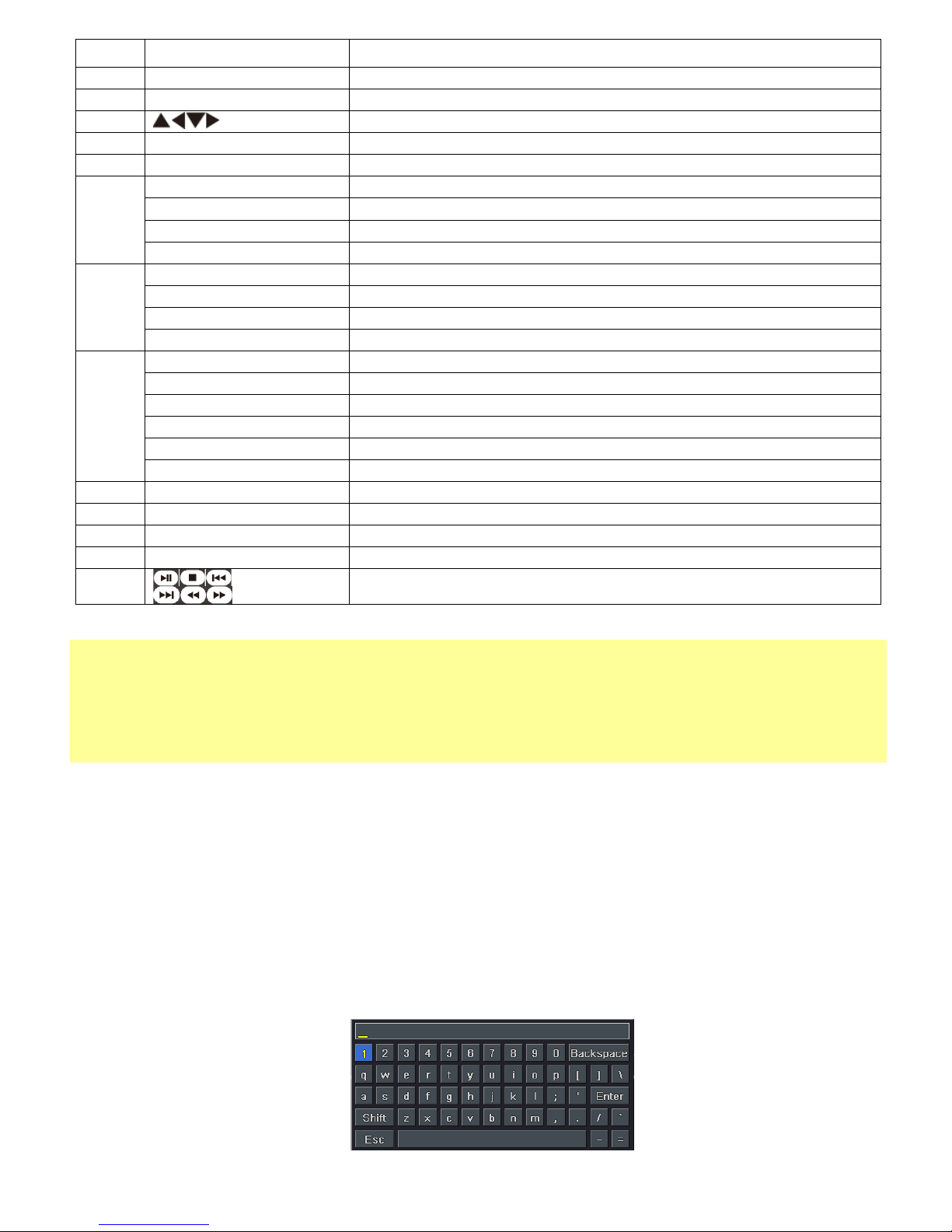
If you want to key in letter or digit, please move mouse to textbox then single click left button on textbox.
The OSD keyboard will pop up as following,