Oliver 10062 User manual


READ AND UNDERSTAND ALL INSTRUCTIONS IN THIS MANUAL BEFORE
ATTEMPTING TO ASSEMBLE OR OPERATE THE MACHINE.
FOLLOW THE INSTRUCTIONS AND THINK SAFETY!
THE OWNER OF THIS MACHINE IS SOLELY RESPONSIBLE FOR THE SAFETY OF ANYONE USING
THIS MACHINE. SUCH RESPONSIBILITY INCLUDES BUT NOT LIMITED TO THE FOLLOWING:
•PROPER ASSEMBLY, OPERATION, INSPECTION, MAINTENANCE, AND RELOCATION OF
THE MACHINE.
•PROPER TRAINING FOR THE OPERATORS AND ENSURES THIS MANUAL IS AVAILABLE
AT ALL TIMES.
•USAGE AUTHORIZATION.
•USAGE OF SAFETY AND PROTECTION DEVICES.
OLIVER MACHINERY DISCLAIMS ANY LIABILITY FOR MACHINES THAT HAVE BEEN ALTERED OR
ABUSED. OLIVER MACHINERY RESERVES THE RIGHT TO EFFECT AT ANY TIME, WITHOUT PRIOR
NOTICE, THOSE ALTERATIONS TO PARTS, FITTINGS, AND ACCESSORY EQUIPMENT WHICH THEY
MAY DEEM NECESSARY FOR ANY REASON WHATSOEVER.
** SAVE THIS MANUAL FOR FUTURE REFERENCE. **
PROP 65 NOTICE
WARNING: Drilling, sawing, sanding, or machining wood products can expose you to wood dust
and/or other chemicals that are known to the State of California to cause cancer, birth defects,
or other reproductive harm.
Some examples of these chemicals are:
•Lead from lead-based paints.
•Crystalline silica from bricks, cement, and other masonry products.
•Arsenic and chromium from chemically treated lumber.
Avoid inhaling wood dust and other harmful chemicals. Use a dust mask and/or other safety
devices for personal protection.
For more information, visit http://www.P65Warnings.ca.gov/wood

Table of Contents
Introduction············································· 5
Specifications ·········································· 6
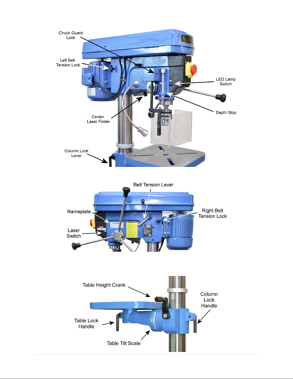
Identification ··········································· 9
Safety·····················································11
General Safety Guidelines·························11
Safety Guidelines Specific to Drill Press ·····12
Electricals ···············································14
Minimum Circuit Size Requirement···········14
Grounding················································14
Electrical Wiring ·······································14
Setup······················································15
Shop Preparation······································15
Space Requirement ·········································15
Load Limits ······················································15
Electricals ························································15
Lighting····························································15
Safety Labels ···················································15
Dust Collection ················································15
Receiving··················································16
Moving Machine into the Shop·······················16
Unboxing ·························································16
Inventory·························································17
Cleaning···················································19
Assembly ·················································20
Test Run···················································25
Operation ·············································· 27
Preparation··············································27
Drill Press Adjustments·····························29
Table Adjustments ··········································29
Changing Drill Bits ···········································30
Changing Speed···············································31
Adjust Depth Stop ···········································31
Changing Chuck···············································32
Drilling ·····················································33
Accessories ············································ 34
Maintenance ········································· 35
Maintenance Schedule ·····························35
Troubleshooting····································· 36
Mechanical / Electrical Issues····················36
Operation / Quality-Related Issues ···········37
Wiring Diagram ····································· 38
Parts List················································ 39
Maintenance Record······························ 44
Notes····················································· 45
Warranty and Service····························· 46
Appendix ··············································· 47
US Standard –Metric Conversion Chart·····47

10062 Drill Press OLIVERMACHINERY.NET 5|Page
Introduction
Thank you for choosing Oliver! This manual contains important information on how to safely set up,
operate, and maintain this machine. Please take the time to read through this manual and make sure you
understand all instructions.
While this manual may provide tips on improving the result of your workpiece, the manual is not intended
as a substitute for formal woodworking or metalworking training. If you need to know how to safely
complete a task, please consult knowledgeable and qualified sources before proceeding further.
We made every effort to keep this manual up-to-date. Instructions, specifications, drawings, and
photographs in this manual should match the machine delivered. If you find any differences, or anything
that seems confusing in this manual, or some instructions are not available, please check our website for
an updated version:
WWW.OLIVERMACHINERY.NET/MANUALS
Alternatively, you can contact our technical support for help:
1-800-559-5065
Before calling, please note down the serial number of the machine.
You can find the information on a label located on the right side of
the headstock. This information is needed to provide proper
technical support and to determine if an updated manual is
available for your machine.
Please let us know how well this manual serves you. If you have any suggestions, please call the number
above or email us at:
info@olivermachinery.net
We love to hear from our customers and make improvements.

6 | Page Oliver Machinery 10062 Drill Press
Specifications
Quick View
Model
10062 Drill Press
Stock Number
10062.001
Type
Floor Drill Press
Motor
TEFC Induction Motor, 3/4 HP, 115V, 1Ph
Speed Range
240 –3400 RPM
Swing
17"
Drilling Capacity (Mild Steel)
3/4"
Chuck
JT-3 Key Chuck with 5/8" capacity
Table
Square Cast Iron Table, 12" x 12"
Spindle Travel
3-1/4"
Max Spindle to Table Distance
26-3/8"
Dimensions
64-1/2”(H) x 16”(W) x 29”(D)
Footprint
11-3/4”(W) x 19-1/2”(D)
Weight
187 lbs.
Warranty
1 Year (Motor and electronics)
2 Years (All other parts)
Product Dimensions
Assembled Dimensions
64-1/2”(H) x 16”(W) x 29”(D)
Footprint
11-3/4”(W) x 19-1/2”(D)
Fully Assembled Weight
187 lbs.
Shipment Info
Type
Cardboard box
Content
Drill press and accessories
Dimensions
54-1/2” (L) x 21”(W) x 10-3/4”(H)
Weight
198 lbs.
Approximate Setup Time
90 minutes
Must Ship Upright
NO
Stackable
YES

10062 Drill Press OLIVERMACHINERY.NET 7|Page
Electricals
Power Requirement
115V, 1Ph, 60Hz
Full Load Current Rating
12A
Recommended circuit size
15A
Power Switch Type
Push button switch with safety mechanism
Connection Type
NEMA 5-15 Plug with 50" 16 AWG Cord
Motor
Motor Type
TEFC Induction Motor
Horsepower
3/4 HP
Speed
1720 RPM
Power Transfer Mechanism
V-belt and pulleys
Bearing type
Permanently sealed ball bearing
Spindle
Swing
17"
Travel
3-1/4"
Spindle taper
MT-2
Max. spindle to table distance
26-3/8"
Max. spindle to base distance
48-1/8"
Quill diameter
2-1/16"
Chuck
Capacity
5/8"
Type
JT-3 Key Chuck
Speed and Drilling Capacity
Spindle Speed Range
240 –3400 RPM
Total number of speeds available
16
Drilling Capacity (Mild Steel)
3/4"

8 | Page Oliver Machinery 10062 Drill Press
Measurements
Measurement Unit
Inch
Measurement Devices
Depth Scale
Laser Center Finder
Equipped
Safety
Chuck Guard
Polycarbonate Chuck Guard
Sound Rating @ 2' distance
80 dB
Center Finder Laser Class
Class II
Others
Serial Number Location
On the left side of the headstock
Work Lamp Type
LED
Certification
CSA 183999
Country of Origin
China
Table
Table Shape and Dimensions
Square, 12" x 12"
Max. Table Tilt
+/- 45°
Table Swivel Around Column
360°
Number of slots
4
Table Height Above Ground
24-5/8" –43-1/4"
Table Lifting Mechanism
Rack and Pinion
Material
Precision ground cast iron
Base and Column
Base Dimensions
11-3/4”(W) x 19-1/2”(D)
Base Material
Cast iron
Column Diameter
3-5/32"
Column Material
Steel

10062 Drill Press OLIVERMACHINERY.NET 9|Page
Identification

10 | Page Oliver Machinery 10062 Drill Press

10062 Drill Press OLIVERMACHINERY.NET 11 |Page
Safety
Oliver Machinery has made every attempt to provide a safe, reliable, easy-to-use piece of machinery.
Safety, however, is ultimately depending on the individual machine operator. Before operating this
machine, please become familiar with the following safety labels and guidelines.
DANGER
This indicates an imminently hazardous situation which, if not avoided, WILL cause
death or serious injury.
WARNING
This means if the warning is not taken seriously, it CAN cause death or serious injury.
CAUTION
This means if precaution is not taken, it MAY cause injury.
IMPORTANT
This is a tip for properly operating the machine to avoid machine damage.
General Safety Guidelines
1. FAMILIARIZE yourself with all safety instructions found in this manual. Know the limitations and
hazards associated with this machine. Do not operate/service this machine until you are properly
trained.
2. ELECTRICAL GROUNDING, when done properly, reduce the risk of electrocution, shocks, and fire.
Make certain that the machine frame is electrically grounded and that a ground lead is included in the
incoming electrical service. In cases where a cord and a plug are used, make certain that the grounding
plug connects to a suitable ground. Follow the grounding procedure indicated in the electrical code
of your area.
3. DISCONNECT the machine from power before performing any service, maintenance, or adjustments.
A machine under repair should be RED TAGGED to show it should not be used until the repair is
complete.
4. EAR PROTECTION: Use hearing protective devices where the noise exceeds the level of exposure
allowed in Section 1910.95 of the OSHA Regulations. When in doubt, use it.
5. GUARDS: Keep machine guards in place for all applicable operations. If any guards are removed for
maintenance, DO NOT OPERATE the machine until all guards are reinstalled. Check clearance between
the guards and the cutter before starting the machine.
6. WORKPLACE SAFETY: Keep the floor around the machine clean. Scrap material, sawdust, oil, and
other liquids increase the risk of tripping or slipping. Be sure to clean up the table before starting the
machine. Make certain the work area is well-lighted and that a proper exhaust system is used to
minimize dust. Use anti-skid floor strips on the floor area where the operator normally stands and
mark off the machine work area. Wear protective footwear. Provide adequate workspace around the
machine.
7. ACCESS CONTROL should be enforced so only trained personnel can access the work area and operate
the machine. Use a childproof power switch when applicable.
8. STAY ALERT at all times. Do not operate this machine while under the influence of drugs/alcohol or
when not feeling well.

12 | Page Oliver Machinery 10062 Drill Press
9. NEVER STAND ON MACHINE. This prevents injuries from tipping-related accidents and accidental
contact with cutters.
10. REPLACEMENT PARTS: Use only genuine Oliver Machinery replacement parts and accessories
recommended for this machine. Generic parts made by other manufacturers may create a safety
hazard and WILL void the factory warranty and other guarantees.
11. PROPER USE: Do not use this machine for anything other than its intended use. If used for other
purposes, Oliver Machinery disclaims any real or implied warranty and holds itself harmless for any
injury or damage which may result from that use.
Safety Guidelines Specific to Drill Press
Before Work Begins:
1. INSPECT WORKPIECE: This drill press is primarily designed for woodworking operations, and it is also
suitable for drilling some other materials, such as soft steel. Avoid drilling materials that may
disintegrate or catch fire. Avoid drilling materials that contain harmful chemicals, as this can produce
harmful chemical dust.
2. CHECK DRILL BIT AND CHUCK: Make sure the drill bit is sharp, clean, balanced, and free from damage.
Replace dull or damaged drill bit. Never use a drill bit to drill material types that it is not compatible
with. Make sure the drill bit is securely fastened and the chuck key is not attached to the chuck before
starting the drill press.
3. USE CORRECT SPINDLE SPEED: Some drill bits have a maximum operating speed recommended by
the manufacturer. Never set the drill press to go beyond this speed, or the drill bit can overheat or
even disintegrate, which can cause serious injuries or even death.
4. SECURE WORKPIECE, TABLE, AND HEADSTOCK: Mount the workpiece on the table with clamps or
drill vise. Never hold the workpiece by hand during operation. Lock the table assembly to maintain
the alignment between the drill bit and the workpiece. Failure to do so may cause the drill bit to bind
into the workpiece. This can damage the drill bit and the workpiece, and cause serious injuries.
5. EYE PROTECTION: Always wear an approved safety face shield/goggles/glasses that complies with
ANSI Z87.1 and CSA Z94.3 standards. Common eyeglasses are not safety glasses and may not provide
adequate protection.
6. LASER WARNING: This drill press is equipped with a class II laser center finder. DO NOT stare into the
laser beam or view it directly with an optical instrument.
7. AVOID ENTANGLEMENT: Roll up sleeves above elbows. Remove all loose outer clothing and confine
long hair. Remove tie, rings, watch, and other jewelry. Do not wear gloves unless it is instructed to
perform certain steps in the manual.
8. CHECK CHUCK GUARD: Make sure the guard is installed and there are no signs of damage. Before
starting the drill press, shield the chuck with the guard and lock it in place.

10062 Drill Press OLIVERMACHINERY.NET 13 |Page
9. PROTECT TABLE: The drill bit should align with the center hole on the table. For drill bits like Forstner
bits, the center hole may not be big enough for the drill bit to pass through. Support the workpiece
with a backer board to protect the tool and avoid tearing out the back of a workpiece.
10. SUPPORT LONG WORKPIECE to prevent the workpiece and the drill press from tipping.
11. DUST COLLECTION SYSTEM reduces harmful dust from drilling. Please set up the drill press with dust
extraction accessories when available.
12. NOT A MILLING MACHINE: A drill press is only designed for downward cutting. Never use the drill
press for sideway cutting with milling bits. Doing so can damage the drill press and cause the chuck to
dislodge from the drill press.
When Drilling:
1. THE 3-INCH RULE. Keep your hands at least three inches away from the drill bit when the machine is
running. Do not clear debris with your hands while the drill press is running.
2. PROPER FEEDING keeps the workpiece under control. NEVER start the drill press with the drill bit
engaging the workpiece. NEVER start drilling into the workpiece until the motor has reached its full
speed. Maintain proper feed rate and downward pressure.
3. DRILLING ANGLED HOLES: Be extra careful when drilling angled holes. The lateral force may cause the
drill bit to twist and break. Reduce feed rate and use sharp bits.
4. PREVENT OVERHEATING by using lubricant when drilling metal, plastic, and some other non-wood
materials. Overheating damages the workpiece and the drill bit, and creates a fire hazard.
After Operation
1. STOP THE MACHINE if the operator leaves the machine for any reason.
2. WAIT until the machine comes to a complete stop.
3. CLEAN UP and CLOSE POWER SWITCH COVER before departure.

14 | Page Oliver Machinery 10062 Drill Press
Electricals
WARNING
Faulty electrical work can cause electrocution and is a fire hazard.
All electrical work must be completed by a licensed electrician and must meet the
local electrical code in your area, or the warranty is void.
Minimum Circuit Size Requirement
Model
Minimum Circuit Size Required
10062 Drill Press
15A
Please ensure the electrical circuit for this machine meets the minimum circuit size requirement. The
minimum circuit size requirement applies to a dedicated circuit that provides power to one drill press. If
more machines are sharing the same circuit, consult a licensed electrician to ensure the designated circuit
is properly sized for safe operation.
If a circuit is available but not meeting the minimum circuit size requirement listed above, a new circuit
must be installed for this machine.
Grounding
WARNING
Improper grounding can cause electric shock, fire, and equipment damage.
Proper grounding reduces the risk to the operator in the event of electrical malfunction or breakdown.
This machine must be connected to the grounding conductor when available, and all grounding
connections must meet or exceed the electrical code requirements in your area. Furthermore, all grounds
must be verified and must meet or exceed the electrical requirement of the machine. If grounding is not
available, consider the use of a GFCI protection device as an alternative if this complies with the electric
code in your area.
Electrical Wiring
This machine is pre-wired for 115V with a cord and a NEMA 5-15 plug. The drill press should be situated
near an electrical outlet. If you need to use an extension cord to connect to a power source, select a
durable cord type with high-temperature rating (90C° or above). Use the minimum amount of extension
cord as needed.
Minimum cord size (AWG) required based on amperage draw and length of the cord:
Amps
Power Cord Length
25 feet
50 feet
75 feet
100 feet
> 100 feet
5 to 8
14
14
14
12
Not
Recommended
8 to 12
14
14
12
10
12 to 15
12
12
10
10
WARNING
Use properly sized wires that meet or exceed the power requirement of your
machine. Using undersized wires may cause overheating and increase the risk of fire
and machine damage.

10062 Drill Press OLIVERMACHINERY.NET 15 |Page
Setup
Shop Preparation
Space Requirement
The dimensions of 10062 Drill Press are 64-1/2”(H) x 16”(W) x 29”(D). You will need
additional space for manipulating your workpiece, electrical connection, and dust
collection.
Load Limits
This drill press weighs 198 lbs. Please ensure all lifting tools and structures have
adequate load capacity for transporting and supporting the total weight of this
machine, the operator, and related items.
Electricals
Ensure a properly sized circuit is nearby the machine. If the machine is to be hardwired, there must be a
readily accessible power disconnect nearby so that the machine can be disconnected from the power
source for servicing and adjustments. If the machine is to be connected with a cord and a plug, please
ensure a matching outlet is installed nearby.
Please refer to the section "Electricals" in this manual for details regarding electrical requirements.
Lighting
Install overhead, non-glare lighting for the work area near the drill press. The drill press also comes with
a flexible gooseneck LED light to provide a focused beam.
Safety Labels
If this machine introduces a new safety hazard to your workplace, display proper warning signs in highly
visible locations.
Dust Collection
Wood dust is a health hazard and can be reduced by using a dust collection system. When it can be done
safely, mount a dust hood near the table to remove dust. Check the air suction of the dust collection
system regularly to ensure filters and pipes are not clogged.
Dust masks should be available for using the drill press.

16 | Page Oliver Machinery 10062 Drill Press
Receiving
Your shipment should come in one box. Upon receiving your shipment, check for any significant damages
before signing the delivery confirmation. Please keep all packaging materials until this drill press passes
the test run (see page 25 for details) and you are satisfied with this machine.
Moving Machine into the Shop
Your machine will be delivered by freight service, and it will be left outside of your workshop by default.
On the day of delivery, please be sure help is available to move the machine to its final location.
WARNING
10062 Drill Press has a shipping weight of 198 lbs.
Safe moving techniques and proper lifting equipment are required, or serious
personal injury may occur.
WARNING
Your shipment may be secured by the straps. Do not lift your shipment by the
strap. They are not designed to hold the total weight of your shipment. They may
snap without warning and cause serious injury and machine damage.
Always wear safety goggles and gloves when removing straps, as they may spring
back violently when released and cause injury.
Unboxing
You should find all parts and accessories packed inside a box like this.
IMPORTANT
If items are damaged on arrival, please call us immediately at 1-800-559-5065

10062 Drill Press OLIVERMACHINERY.NET 17 |Page
Inventory
Carefully unwrap the packaging and inventory the items received:

18 | Page Oliver Machinery 10062 Drill Press
Item
Description
Quantity
1
Column, rack, and rack collar
1
2
Base
1
3
Bolts and lock washers for mounting the column
4 sets
4
Table Support Bracket
1
5
Table height adjustment crank
1
6
Headstock
1
7
Table
1
8a
Chuck guard rod –Upper
1
8b
Chuck guard rod –Middle
1
8c
Chuck guard rod - Lower
1
8d
Chuck guard rod mounting washers and nuts
2 sets
8e
Chuck guard screen
1
9a
Feed handle knobs
3
9b
Feed handle rods
3
10
Belt cover knob
1
11
Arbor
1
12
Chuck
1
13
Hex key set (3/4/5 mm)
1
14
Drift key
1
15
Chuck key
1
NOTICE: If you cannot find an item in the list above, please check if it is still attached to the packaging.
Occasionally the item may have been pre-installed in the factory. See "Parts List" on page 39 to check if a
component is included or installed.
NOTICE: This machine comes with various standard-sized, non-proprietary parts. If any of these parts are
missing, we are happy to deliver them to you. To have the machine up and running as soon as possible,
you can also find these parts at your local hardware store.
Additional Items Recommended for Machine Setup
Item
Purpose
Safety Glasses
Protection
Disposable Gloves
Protection
Paper Towel / Rags
Cleaning
Rust Inhibitor
Cast iron rust protection.
Metric Wrench Set
Assembly
Metric Hex Wrench Set
Assembly
Retaining Ring Plier
Assembly

10062 Drill Press OLIVERMACHINERY.NET 19 |Page
Cleaning
To prevent rusting during transportation and storage, the
unpainted cast iron surfaces of the drill press table and
base are protected by heavy-duty rust preventive grease
and plastic film. The machine should be cleaned before
assembly. Remove the packaging and wipe off the grease
with paper towels or rags. WD-40 can thin the grease and
make cleaning easier. Do not use harsh solvents such as
acetone which can damage the paint, and NEVER use
gasoline or any highly flammable solvent as degreaser.
After the initial cleaning, routinely coat the unpainted cast iron surface with rust preventive such as
Boeshield® T-9 or paste wax. Do not use rust preventives that contain silicone, which is known to interfere
with certain finishes and glues.
WARNING
Never use gasoline or any highly flammable chemical as degreaser. These chemicals
can cause fire and explosion.
Discard oily rags in a fireproof container and keep them away from combustible
materials. Oily rags can heat up and trigger spontaneous combustion under certain
conditions.

20 | Page Oliver Machinery 10062 Drill Press
Assembly
This machine must be assembled before it can be operated. Please refer to the section "Inventory" on
page 17 and gather the items by their numbers for assembly.
WARNING
Drill press 10062 weighs 198 lbs. and it is top-heavy. It is recommended to have at
least two adults assemble and move the drill press. Serious injury and machine
damage can occur when the drill press is not handled properly.
Drill press Assembly
1. Bolt the column (#1) to the base (#2) using
four sets of bolts and the spring washers (#3).
2. Loosen the screw on the rack collar, then
slide the rack collar off from the column (#1).
Set the rack and the collar aside.
3. Locate the table bracket (#4). Make sure the
worm gear and the pinion are in their proper
location.
4. Seat the rack into the slot of the table
bracket so the rack makes contact with the
pinion.
Make sure the table bracket and the rack are
properly oriented. The table bracket has a
dome-shaped top, and the rack has the
tapered end pointing up.
Slide both pieces onto the column (#2).
Make sure the rack seats inside the table
bracket slot in this step, as this is a tight fit.
Fit the squared end of the rack into the
friction ring of the base flange.
Table of contents
Other Oliver Power Tools manuals

Oliver
Oliver 4705 User manual

Oliver
Oliver 7660.002 User manual

Oliver
Oliver 10044 User manual

Oliver
Oliver 10060.001 User manual

Oliver
Oliver 4270 User manual

Oliver
Oliver 4705 User manual

Oliver
Oliver 4265C Instruction Manual

Oliver
Oliver 4260 User manual

Oliver
Oliver 4240 User manual

Oliver
Oliver 4265 User manual