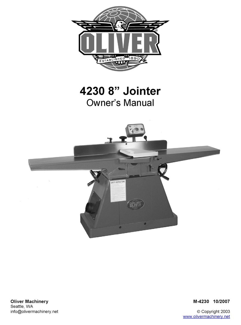
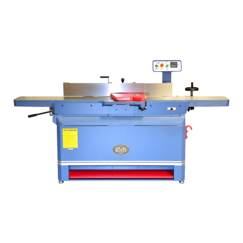
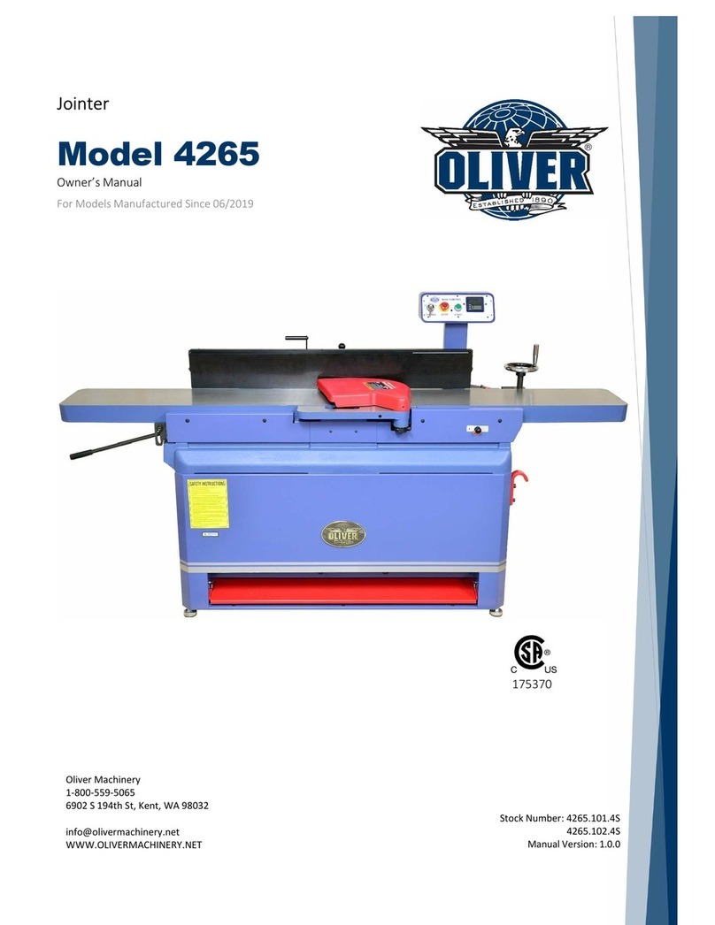
Oliver 4240 User manual

4240 10” Jointer
Owner’s Manual
Oliver Machinery M-4240 01/2015
Seattle, WA Copyright 2003-2015
[email protected] www.olivermachinery.net

2
Warranty
Oliver makes every effort possible to assure that its equipment meets the highest possible standards of
quality and durability. All products sold by Oliver are warranted to the original customer to be free from
defects for a period of 2 (two) years on all parts, excluding electronics and motors, which are warranted
for 1 year. Oliver’s obligation under this warranty shall be exclusively limited to repairing or replacing (at
Oliver’s option) products which are determined by Oliver to be defective upon delivery F.O.B. (return
freight paid by customer) to Oliver, and on inspection by Oliver. This warranty does not apply to defects
due, directly or indirectly, to misuse, abuse, negligence, accidents, unauthorized repairs, alterations, lack
of maintenance, acts of nature, or items that would normally be consumed or require replacement due to
normal wear. In no event shall Oliver be liable for death, personal or property injury, or damages arising
from the use of its products.
Warning
Read this manual thoroughly before operating the machine. Oliver Machinery disclaims any liability for
machines that have been altered or abused. Oliver Machinery reserves the right to effect at any time,
without prior notice, those alterations to parts, fittings, and accessory equipment which they may deem
necessary for any reason whatsoever.
For More Information
Oliver Machinery is always adding new Industrial Woodworking products to the line. For complete, up-to-
date product information, check with your local Oliver Machinery distributor, or visit
www.olivermachinery.net
Oliver Machinery makes every effort to supply the most up to date changes and accurate photos/specs.
Oliver reserves the right to make changes to machinery and specifications without prior notice.

3
WARNING
Read this manual completely and observe all warning labels on the machine. Oliver Machinery has made
every attempt to provide a safe, reliable, easy-to-use piece of machinery. Safety, however, is ultimately
the responsibility of the individual machine operator. As with any piece of machinery, the operator must
exercise caution, patience, and common sense to safely run the machine. Before operating this product,
become familiar with the safety rules in the following sections.
Always keep guards in place and in proper operating condition.
Never reach around or under the jointer.
1. If you are not properly trained in the use of a jointer do not use until the proper training has been
obtained.
2. Read, understand and follow the safety instructions found in this manual. Know the limitations and
hazards associated with this machine.
3. Electrical grounding: Make certain that the machine frame is electrically grounded and that a
ground lead is included in the incoming electrical service. In cases where a cord and plug are used,
make certain that the grounding plug connects to a suitable ground. Follow the grounding procedure
indicated in the National Electrical Code.
4. Eye safety: Wear an approved safety shield, goggles, or glasses to protect eyes. Common
eyeglasses are only impact-resistant, they are not safety glasses.
5. Personal protection: Before operating the machine, remove tie, rings, watch and other jewelry and
roll up sleeves above the elbows. Remove all loose outer clothing and confine long hair. Protective
type footwear should be used. Where the noise exceeds the level of exposure allowed in Section
1910.95 of the OSHA Regulations, use hearing protective devices. Do not wear gloves.
6. Guards: Keep the machine guards in place for every operation for which they can be used. If any
guards are removed for maintenance, DO NOT OPERATE the machine until the guards are
reinstalled.
7. Work area: Keep the floor around the machine clean and free of scrap material, saw dust, oil and
other liquids to minimize the danger of tripping or slipping. Be sure the table is free of all scrap,
foreign material and tools before starting to use the machine. Make certain the work area is well
lighted and that a proper exhaust system is used to minimize dust. Use anti-skid floor strips on the
floor area where the operator normally stands and mark off machine work area. Provide adequate
work space around the machine.
8. Jointer position: Position the jointer so that in case of material kick back the flying piece will not
injure workers.
9. Material condition: Do not attempt to joint boards with loose knots or with nails or other foreign
material.
10. Operator: Always use push blocks. Maintain a balanced stance and keep your body under control
at all times.
11. Before starting: Before turning on machine, remove all extra equipment such as keys, wrenches,
scraps, and cleaning rags away from the machine and off the table.

4
12. Careless acts: Give the work you are doing your undivided attention. Looking around, carrying on a
conversation, and “horseplay” are careless acts that can result in serious injury.
13. Disconnect all power sources: Before performing any service, maintenance, adjustments or when
changing blades. A machine under repair should be RED TAGGED to show it should not be used
until the maintenance is complete.
14. Job completion: If the operator leaves the machine area for any reason, the jointer should be
turned "off" and the cutter head should come to a complete stop before leaving.
15. Replacement parts: Use only genuine Oliver Machinery factory authorized replacement parts and
accessories; otherwise the warranty and guarantee are null and void.
16. Misuse: Do not use this Oliver jointer for other than its intended use. If used for other purposes,
Oliver disclaims any real or implied warranty and holds itself harmless for any injury or damage which
may result from that use.
17. Drugs, alcohol and medication: Do not operate this machine while under the influence of drugs,
alcohol, or any medication.
18. This machine is designed for planing wood products only. Do not use to cut any kind of metal or
substance other then wood.
19. Never start the jointer while a workpiece is in contact with the blade.
20. Raise or lower the tables only when the machine has been turned “off” and the cutter head has
come to a complete stop.
21. Make sure the cutter head is running in the proper direction. The knives should be turning toward the
infeed table.
22. Health hazards: Some dust created by power sanding, sawing, grinding, drilling and other
construction activities contains chemicals known to cause cancer, birth defects or other reproductive
harm. Some examples of these chemicals are:
Lead from lead-based paint.
Crystalline silica from bricks and cement and other masonry products.
Arsenic and chromium from chemically-treated lumber.
Your risk from these exposures varies, depending on how often you do this type of work. To reduce
your exposure to these chemicals, work in a well-ventilated area, and work with approved safety
equipment, such as those dust masks that are specifically designed to filter out microscopic particles.
Familiarize yourself with the following safety notices used in this manual:
CAUTION: (This means that if precautions are not heeded, it may result in minor or moderate injury
and/or possible machine damage)
WARNING: (This means that if precautions are not heeded, it could result in serious injury or possibly
even death).

5
Table of Contents Page Number
Warranty ........................................................................................................................................................ 2
Warnings .................................................................................................................................................... 3-4
Table of Contents .......................................................................................................................................... 5
Specifications ................................................................................................................................................ 5
Uncrating the Machine .................................................................................................................................. 6
Contents ........................................................................................................................................................ 6
Machine Preparation and Setup ................................................................................................................... 6
Dust Collection .............................................................................................................................................. 7
Electrical Connections ................................................................................................................................... 7
Control Switch ............................................................................................................................................... 7
Fence ............................................................................................................................................................ 8
Installation of the Fence ................................................................................................................................ 8
Fence Legend ............................................................................................................................................... 8
Adjustment of the 90 Degree Stop ................................................................................................................ 8
Fence Operation ........................................................................................................................................... 8
Knives ........................................................................................................................................................... 9
Knife Removal ............................................................................................................................................... 9
Knife Setting ................................................................................................................................................ 10
Adjusting the Outfeed Table........................................................................................................................ 10
Spiral Head Option .................................................................................................................................... 11
Helical Head Option .................................................................................................................................. 12
Operation ................................................................................................................................................... 13
Hand Safety and Placement ....................................................................................................................... 13
Jointing ........................................................................................................................................................ 13
Direction of the grain ................................................................................................................................... 13
Edging ......................................................................................................................................................... 13
Facing .......................................................................................................................................................... 14
Beveling....................................................................................................................................................... 14
Rabbeting .................................................................................................................................................... 14
Adjusting the Infeed Table Height ............................................................................................................... 15
Maintenance .............................................................................................................................................. 16
V-Belts ......................................................................................................................................................... 16
Lubrication ................................................................................................................................................... 16
Knives .......................................................................................................................................................... 16
Table Leveling ............................................................................................................................................. 16
Troubleshooting ........................................................................................................................................ 17
Specifications
Model No. ................................................................................................................................................ 4240
Stock No (3HP, 1PH, 220 Volt) ........................................................................................................ 4240.001
Stock No.(5HP, 3PH, 220/440 Volt, pre-wired 220 Volt) ................................................................. 4240.004
Stock No.(3HP, 1PH, 220 volt, spiral head) .................................................................................... 4240.101
Stock No (5HP, 3PH, 220/440 volt, pre-wired 220 Volt, spiral head) .............................................. 4240.104
Infeed Table Travel (in.) ............................................................................................................................. 5/8
Cutterhead speed (RPM) ........................................................................................................................ 5000
Number of Knives (Straight) .......................................................................................................................... 4
Number of Knives (Spiral) ............................................................................................................................. 3
Rabbeting Capacity (in.) ............................................................................................................................. 5/8
Dust Port Diameter (in.) ................................................................................................................................ 6
Table Dimensions (L x W/in.) .............................................................................................................. 84 x 11
Table Height (In.) .................................................................................................................................. 30-1/2
Fence Dimensions (L x H/in.) .......................................................................................................... 52 x 4-7/8
Fence Tilts (deg.) ................................................................................................................................. 90 - 45
Positive Stops (deg.) ....................................................................................................................... 90 and 45
Shipping Dimension (L x W x H/in.) ............................................................................................ 91 x 31 x 38
Overall Dimensions ..................................................................................................................... 84 x 30 x 37
Gross Weight (lbs.) ................................................................................................................................... 900
CFM ............................................................................................................ 885CFM at 4500FPM air velocity

6
Oliver 4240 – 10” Jointer
Uncrating the Machine
The machine should arrive as show in Figure
1. Uncrate the machine and inspect the unit
for signs of shipping damage. If damage is
found, contact your dealer immediately.
Unbolt the machine from the pallet. Retain all
packaging materials in case it becomes
necessary to ship the machine to another site.
Contents: (Figures 2 & 3)
1. 10” Jointer
2. Fence assembly
3. Blade guard
4. Fence attachment bolt
5. Knife Setting guage
6. Two wrenches
7. Allen key
Machine Preparation and Setup
WARNING!
The equipment used to lift this machine
must have a rated capacity at, or above the
weight of the jointer. Failure to comply
may cause serious injury!
The jointer must be positioned on a smooth,
level surface. The area must be well lit and
have plenty of room to maneuver with large
pieces of wood.
Level the jointer front to back and side to side
using a level placed on the table. Use shims
under the corners, if necessary, but make sure
the jointer is stable before being placed into
service.
Clean all rust protected surfaces with a
commercial solvent. Do not use acetone,
gasoline, lacquer thinner or any type of
flammable solvent, or a cleaner that may
damage paint. Cover cleaned surfaces with
WD-40 or a 20W machine oil.
Figure 1
Figure 2
Figure 3

7
Dust Collection
The 6” dust collection port (A, Figure 4) is
located below the outfeed table. Typically flex
hose is used to run from this point to a central
trunk line.
Note: Do not operate the jointer without dust
collection.
Electrical Connections
WARNING!
Electrical connections and wiring must be
performed by a certified electrician. The
machine must be properly grounded.
Failure to comply may cause serious
injury!
This jointer can be 1 or 3-Phase based on
your order and is wired for 220 volt. If on 3
phase you need to switch from 220V to 440V,
have a certified electrician make the changes.
As well, a step down control transformer will
have to be installed.
For 3 phase machines, bring your incoming
power leads up through the bottom right hole
of the case and tie to L1, L2, L3 as shown in
Figure 5. Then tie your earth ground to the
ground connection in the box.
For 1 phase machines, tie your incoming
power leads to L1 and L3.
Make sure the voltage of your power supply
matches the specifications on the motor plate
of the machine.
With 3-Phase power verify the cutter head is
turning in the proper direction. If rotation is
incorrect, swap two of the phases to reverse.
Note: If running from a phase converter
ensure the ‘high leg’ of the converter does not
feed the control circuit.
Control Switch
For shipping purposes the control switch is
mounted as shown by ‘A’ in figure 6. Remove
the two mounting bolts and reposition the
switch as shown by ‘B’ while re-securing using
the two bolts.
Figure 4
Figure 5 (3 Phase)
Figure 6

8
Fence
WARNING!
Never make any adjustments with the
machine running!
Installation of the Fence
The fence, although completely assembled,
requires bolting to the machine.
1. Set the fence bracket (Figure 8) on top of
the fence support bracket (Figure 7) lining
up the key slides ‘A’ with the guides on the
bottom of the fence bracket. Install the
width lock handle and special washer with
the tabs facing up into the slot of the fence
support bracket. For rabbeting the handle
should be inserted into the rear hole as
shown in Figure 8.
Fence Legend
The various adjustments, locks and handles
are shown in Figure 8.
A. 90 degree adjust bolt.
B. Angle lock handle.
C. 90 degree flip stop.
D. 45 degree adjust bolt.
E. Width lock handle.
F. Fence angle adjust handle.
Adjustment of the 90 Degree Stop
1. Lay a square on the infeed table as shown
in Figure 9.
2. Loosen the angle lock handle (B, Figure
8).
3. Ensure the 90 degree flip stop (C, Figure
8) is in the 90 degree position.
4. Loosen the jam nut on the 90 degree
adjusting bolt (A, Figure 8) and adjust the
bolt against the flip stop until the fence
becomes true with the square.
5. Tighten the jam nut while holding the bolt
in position.
Fence Operation
To tilt the fence, see Figure 8. Loosen angle
lock handle ‘B’, flip up the stop ‘C’, and tilt the
fence with the fence angle adjusting handle ‘F’
to the desired angle. Use a protractor or
adjustable triangle to set the angle. A 45
degree stop, ‘D’ is provided for quick set-up at
this angle.
To adjust the cutting width loosen the lock
handle ‘E’ and move the fence to the desired
position. .
Once any adjustments are made be sure to
lock them into place before jointing.
Figure 7
Figure 8
Figure 9

9
Knives
WARNING!
The knives are extremely sharp. Use
caution when handling.
Knife Removal
1. To expose the cutterhead, move the fence
all the way back.
2. Back down both the infeed and outfeed
tables to their lowest position. Be sure to
loosen the lock on bot the infeed and
outfeed tables before doing so.
3. Now turn the cutterhead by hand until one
of the knives is exposed and accessible.
Use gloves or a rag to prevent injury.
4. Using a 8mm wrench on the knife lock
bolt, release the pressure on the knife by
turning the bolt into the cutterhead as
show in Figure 10. To prevent injury, hold
the wrench with one hand while tapping
the top of the wrench with the other hand
as shown. Do this for all six bolts.
5. Once all the bolts have been turned in
remove the knife.
Knife Setting
Your 10’ jointer is equipped with both jack
screws or springs to aid in knife setting. It is
your choice which method you use.
Method 1: Springs (when using the spring
method make sure the jack screws are turned
down and out of the way)
Note: It is not only important to set the height
of the knife with respect to the cutterhead it is
also important that the outside edge of the
knives be aligned with the rabbeting ledge.
1. With the knife in the slot use a straight
edge on the rabbeting ledge as shown in
Figure 11 to push the knife into alignment
with the edge.
2. Next use the supplied knife guage as
shown to carefully push down on the knife
until it is position as shown in Figure 12.
Make sure the knife makes contact within
the indent as shown by ‘A’ in Figure 12.
3. With the knife held firmly into place back
the knife lock bolts out into the cutterhead
in order to put pressure onto the knife.
Work from the center bolts outward. Do
this in two steps. First loosely, then firmly
the second time.
4. Repeat the above for all knives.
Figure 10
Figure 11
Figure 12

10
Knife Setting (cont.)
Adjusting the Outfeed Table
1. Once the knives are set it is now time to set
the outfeed table. For proper operation the
height of the outfeed table must be set to the
highest point of the cutting circle. To do this,
set a straight edge on the outfeed table as
shown in Figure 13.
2. Carefully adjust the table height by turning
the handwheel (A, Figure 14) while rocking
the cutterhead back and forth as shown by
the arrow in Figure 13. The table will be at
it’s correct height when the knife, at it’s
highest point of the cutting circle, just
scrapes the bottom of the straight edge.
3. Once set, lock into place with the height lock
knob (B, Figure 14).
Note: Failure to adjust the outfeed table will
result in either a curved or sniped work piece.
Method 2: Jack Screws (when using this
method remove the springs and place in
storage)
Note: As described in the previous method, align
the knives with the rabbeting ledge.
1. With the knife in the slot, turn the jack
screws using an allen key (Figure 15) so
that the bevel plus an additional 1/32” of
knife is protruding from the cutterhead.
Note that this 1/32” need not be exact.
4. Next set a straight edge on the outfeed table
as shown in Figure 15 and adjust the
outfeed table height with the handwheel (A,
Figure 14) so that it is level with the knives
5. When properly adjusted, the knife should
just scrape the bottom of the straight edge at
it’s highest point of it’s cutting circle. Use
the jack screws to finely adjust the knife
height at both ends.
6. Once the knife is at the correct height back
the knife lock bolts out into the cutterhead in
order to put pressure onto the knife. Work
from the center bolts outward. Do this in two
steps. First loosely, then firmly the second
time.
7. Repeat the above for all knives.
Figure 13
Figure 14
Figure 15

11
Spiral Head Option
If you purchased a machine with the spiral
cutterhead (Figure 16), instructions for replacing
the knives are as follows.
Figure 16
1. Using an allen key, remove all the screws
‘A’, gib plates ‘B’, and knife ‘C’ as shown in
Figure 17.
Figure 17
2. Set the new knife on the cutterhead as
shown in Figure 18 by lining up the knife
tabs ‘A’ in the slot and the index holes ‘B’
with the holes in the cutterhead.
Figure 18
3. Starting in the middle of the knife, place the
gib plate on the knife and lightly screw in
one of the gib screws so that the knife tab
seats in the slot. Figure 19
Figure 19
4. Begin installing the rest of the gib plates
using the indexing tool (A, Figure 20) to
properly align the knife while tightening the
screws.
Figure 20
5. Repeat the above procedure for all the
knives while making sure to firmly secure all
screws.
6. Set the outfeed table as described on page
10.

12
Operation
WARNING!
Keep all guards in place. Keep hands away
from the cutterhead! Always use push stick
when possible. Failure to comply may cause
serious injury.
Hand Safety and Placement
Never pass the hands directly over the cutter
knife. As one hand approaches the knives
remove it from the stock in an arc motion and
place it back on the stock in a position beyond
the cutter knife. See Figure 21.
When feeding the work piece, pressure is
applied not only toward the cutterhead but
against the fence and down to the table as well.
At the start of the cut, the left hand holds the
material down and toward the fence while the
right hand pushes toward the cutterhead. As the
material crosses the cutterhead the left hand
comes up and over as in Figure 21 to continue
the pressure but now on the outfeed table. As
the right hand approaches the cutterhead it is
time to move it up and over the cutterhead in the
same fashion as the left in Figure 21 all the
while continuing pressure as stated above.
Jointing
In order to craft a good woodworking project, it is
necessary to have a square piece of wood to
start with. The way to do this is with a jointer.
You need one straight edge and one flat face.
After you have these, you can plane to thickness
and rip to width and the resulting piece will be
square and true on all four sides. At this point
you can begin building your project.
Direction of the Grain
To avoid tear out, always feed the material in the
direction of the grain. If the direction of the grain
changes half way through the board, try taking
lighter cuts at a slower feed rate. If the results
are still unsatisfactory, try turning the material
around and feeding the other way. (Figure 22)
Edging
To give a good straight edge for gluing or
joining, set the fence square with the table.
Remove the least amount of material required to
obtain a straight edge. Hold the best face of the
piece firmly against the fence throughout the
feed. When finished you will have a perfect
starting point for your project. (Figure 23)
Figure 21
Figure 22
Figure 23

13
Facing
Once you have a good edge it is time to
eliminate any warp or cup on the board. Keep in
mind the outfeed table is the reference point and
once the material is past the cutterhead,
downward pressure should be applied to the
outfeed table only. Putting downward pressure
on the board over the infeed table will bend any
cup or warp prior to hitting the cutterhead and
after the pressure is released, the cup will spring
back. At the same time try keeping a constant
feed rate in order to give a good smooth cut with
no burn marks. (Figure 24)
Beveling
For beveling (Figure 25), set the fence to the
desired angle using a protractor and lock into
place. Feed the material through pressing firmly
against the fence and tables. Several passes
may be necessary for the desired result.
Rabbeting
WARNING!
Rabbeting requires removal of the blade
guard. Use extreme caution and replace the
guard after completion.
1. Adjust the fence so that the distance
between the edge of the knife and the fence
is equal to the width of the desired rabbet
(Figure 26).
2. Lower the infeed table to the depth of the
rabbet required. If the rabbet is quite deep it
may be necessary to do it in increments.
Figure 24
Figure 25
Figure 26

14
Adjusting the Infeed Table Height
The height of the infeed table with respect to the
cutting circle will determine the amount of
material to be removed from the work piece. To
raise or lower the table, turn the height adjusting
wheel (A, Figure 27) below the infeed table to
the desired height indicated by the guage (C,
Figure 27). For optimum performance and
safety your jointer has a stop pin (B, Figure 27)
to limit the amount of material removal to 1/8”
per pass. However, if a heavier cut is required,
the pin can be pulled out and the table adjusted
to the desired depth.
Figure 27

15
Maintenance
V-Belts
After the first 20 hours of operation it is
necessary to check the tension on of the V-belts.
To do this, open the access panel (A, Figure 28)
by removing the four corner screws. With
medium finger pressure the belt should push in
approximately ½” about midway between the
pulleys. If there is too much play, adjust the
tensioning bolts (A, ,Figure 29). First loosen the
two nuts (not shown in the picture) underneath
the motor bracket and then turn down the top
nuts to increase the belt tension.
Lubrication
Periodically apply a light grease to the tables
up/down lead screw. As well, apply a light oil to
the dovetail ways from time to time to allow ease
of movement.
The cutterhead bearings are permanently
greased for life and do not require care.
Knives
When knives become gummed up with pitch
carefully clean them with a strong solvent. A
knife in this condition will not only give a poor cut
it will allow heat to build up quickly thus putting
undue stress on the machine.
Dull knives can be replaced or sharpened.
Check in your local yellow pages for a
sharpening service. It may be more cost
effective to replace rather than sharpen.
Note; Do not run the machine with dull knives.
Not only will they give a bad cut, the put undue
stress and vibration on the machine thereby
decreasing the life of the machine and damaging
the cutterhead bearings.
Table Leveling
Over time the table gibs will wear causing the
tables to become un-parallel. At this time it
becomes necessary to tighten the gibs using the
set screws (A, Figure 30). First loosen the jam
nuts and then turn in the set screws until they
make good contact with the gibs. Tighten the
jam nuts.
Figure 28
Figure 29
Figure 30

16
Troubleshooting
Description of Symptoms
Possible Cause
Corrective Action
Machine will not start
1. Fuse blown or circuit breaker
tripped
2. Cord Damaged
3. Faulty switch
4. Not connected to power
source
5. No power to machine
6. Emergency stop button
pressed
1. Replace fuse or reset circuit
breaker
2. Have cord replaced
3. Replace switch
4. Check connection
5. Check voltage
6. Rotate emergency stop button
clockwise until it pops out
Cutterhead does not come up to
speed
1. Cable too light or too long
2. Low current
3. Motor not wired for correct
voltage
1. Replace with adequate size
cable
2. Contact local electric
company
3. Refer to motor nameplate for
correct voltage
Unsatisfactory finish
1. Dull Knives
2. Gum or pitch on knives
1. Sharpen or replace knives
2. Clean or replace knives
Excessive vibration
1. Machine not level.
2. Damaged knives
3. Bad V-belts
4. Bent pulley
5. Improper motor mounting
6. Loose hardware
1. Reposition on flat, level
surface
2. Replace knives
3. Replace V-belts
4. Replace pulley
5. Check and adjust motor
6. Tighten hardware
Adjustments do not move freely.
Sawdust and debris in
mechanisms
Clean and regrease
Finished stock is concave on the
end
Knife is higher than the
outfeed table
Adjust the outfeed table to the
highest point of the cutting
circle
Back end of the stock is thicker
than the front end
Knife is higher that the outfeed
table
Adjust the outfeed table to the
highest point of the cutting
circle
Finished stock is concave or
convex in the middle
Tables are not level with each
other.
Level one of the tables to the
other.

Index Part No. Descriptions Spec. Q'ty
1 JH010001 BASE 1
2 JH010002 INFEED TABLE 1
3 JH010003 OUTFEED TABLE 1
4 JH010004 BAR 2
5 JH010005 SCREW 2
6 JH010006 BLADE GUARD 1
7 JH010009 SET BRACKET 1
8 JH010017 BOLT 1
9 JH010056 BALL 1
10 JG010201 HANDWHEEL 2
11 JG010504 BRACKET 2
12 JG010505 BRACKET 2
13 JG010507 BUSHING 2
14 JG010509 SET SCREW 5/16-18NC*1-1/4" 6
15 JG040005 SPRING BRACKET 1
16 JG040007 FIXING SHAFT 1
17 JG040008 SPRING 1
18 PJ010018 HANDLE 2
19 PJ030001 NUT 1
20 HB020908 CAP SCREW 5/16-18NC*3/4" 3
21 HB021012 CAP SCREW 3/8-16NC*1-1/4" 6
22 HB021314 CAP SCREW 1/2-12NC*1-1/2" 6
23 HB030705 SET SCREW 1/4"-20NC*3/8" 2
24 JH0104 LOCK HANDLE 5/16"-18UNC*1-3/8" 3
25 HD010700 HEX NUT 5/16"-18NC 6
27 HE019600 FLAT WASHER 13*28*3t 16
28 HE021200 SPRING WASHER 10.2*17.8*2.5t 4
29 HE021600 SPRING WASHER 13*22.7 4
30 HH010412 KEY 5*5*22 2
31 HI010105 RIVER 2*5 2
32 HJ130400 BEARING 51103 2
34 HA020628 CAP SCREW M10*1.5P*50 4
35 HY013600 FLAT WASHER 8.5*16*2t 2
36 HY016200 FLAT WASHER 10.3*22*2t 4
37 JH010014 BEARING HOSING 1
38 JH010015 CUTTERHEAD DRAW ROD 2
39 JH010016 CUTTERHEAD PULLEY 1
40S JH0L02 SPRIAL CUTTERHEAD 1
40S-1 JH0L0201 SPRIAL CUTTERHEAD 1
40S-2 JH0L0202 BLADE 3
4240 Parts List
1

40S-3 JHOLO2O3 KNIFE LOCK BAR -L 6
40S-4 JH0L0204 KNIFE LOCK BAR -R 6
40S-5 JH0L0204 KNIFE LOCK BAR 6
40S-6 HA090404 ROUND HEAD SCREW M6*14 30
40S-7 PJ250008 KNIFE LOCK PIN 1
40S-8 JE0L0103 PACKING 2
40F JH0L01 FLAT KNIFE CUTTERHEAD ASSY 1
40F-1 JH0L0101 CUTTERHEAD 1
40F-2 JH0L0102 KNIFE 4
40F-3 JH0L0103 KNIFE LOCKING BAR 4
40F-4 JE010102 SCREW FOR KNIFE LOCKING BAR 24
40F-5 HA050304 SCREW M5*0.8P*10 8
40F-6 PJ0L0103 SPRING 8
43 HD011000 HEX NUT 3/8"-24NF 2
45 HE021100 SPRING WASHER 8.2*15.4*2t 1
46 HH030415 KEY 5*5*30 1
47 HJ032100 BEARING 6203-2NSE 1
48 HJ032200 BEARING 6204-2NSE 1
49 HA370510 CAP SCREW M8*1.25P*20 1
50 JH010021 BRACKET 1
51 JH010022 BRACKET 1
52 JH010023 FENCE 1
53 JH010024 KEY 9.5*9.5*300 2
54 JE030001 FIXING BOLT 1
55 JE030009 BOLT 2
56 JE030012 BRACKET 1
57 JE030020 BOLT 4
58 JE0R0101 KNOB 1
59 JE0R0102 SHAFT 1
60 JE260017 NUT 1
61 JG010002 FENCE LINK 1
62 JG010004 ROD 1
63 JG010005 BOLT 1
64 JG010006 FIXING BOLT 1
65 JG010007 T NUT 1/2" 1
66 JG010010 BLOCK 1
67 JG010046 PIN 1
68 HB080914 HLAT HEAD SCREW 5/16-18NC*1-1/2" 1
69 HD010900 HEX NUT 3/8"-16NC 4
70 HG010907 SPRING PIN 4*14 2
71 HT010712 HEX. SCREW 1/4"-20UNC*1-1/4" 2
72 HT010914 HEX. SCREW 5/16-18NC*1-1/2" 1
2

73 HX010500 HEX. NUT 1-4"-20NC 2
74 HX010700 HEX. NUT 5/16"-18NC 1
75 HX011400 HEX. NUT 1-2"-20NC 2
76 JH010031 BASE 1
77 JH010032 COVER 1
78 JH010033 CHIP BRACK 1
79 JH010034 DUST COLLECT 1
80 JH0102 WIRE BOX 1
80 JH010201 SWITCH BOX LOWER COVER 1
80 JH010202 SWITCH BOX UPPER COVER 1
80 JH010203 1
80 JH010204 1
80 HP170100 1/2" 1
80 HS040402 PAN HEAD SCREW M4*0.7P*6 2
80 HS040403 PAN HEAD SCREW M4*0.7P*8 1
80 HS040405 PAN HEAD SCREW M4*0.7P*12 2
80 HY040600 TOOTH WASHER 4.3*8.5*0.45tBW-4) 2
81 JH1F01 ELECTRIC CONTROL BOX ASSY 1
81 JH0B0101 CONTROL BOX 1
81 JH0B0103 SWITCH LABEL PLATE 1
81 JH0B0105 SWITCH WIRE SJT 18AWG*4C 1
81 TJ0B0104 STOP SWITCH XB4-BS542(TE) 1
81 JH0B0105 START SWITCH XB4-BA31(TE) 1
81 PJ080017 KEY SWITCH 7.5A380V 1
81 HA040403 ROUND HEAD SCREW M4*0.7P*8 4
81 HE010800 WASHER 4.3*12*0.8t 4
82A JH0B01 MAG. SWITCH ASSY 3HP.1PH 1
82A-1 PM0B0X01 MAG. SWITCH 3HP.1PH 1
82A-2 PM0B0702 SWITCH PLATE 1
82A-3 HE040800 STAR WASHER BW-5 2
82A-4 HT040916 PAN HEAD SCREW 3/16"-24NC*1-3/4" 2
82A-5 HX010300 HEX NUT 3/16"-24NC 2
82A-6 PM0B0703 FLAT WASHER 20*45*2.5 2
82B JH0B02 MAG. SWITCH ASSY 5HP.3PH 1
82B-1 PM0B0H01 MAG SWITCH 5HP.3PH 1
82B-2 PM0B0702 SWITCH PLATE 1
82B-3 HE040800 STAR WASHER BW-5 2
82B-4 HT040916 PAN HEAD SCREW 3/16"-24NC*1-3/4" 2
82B-5 HX010300 HEX NUT 3/16"-24NC 2
82B-6 PM0B0703 FLAT WASHER 20*45*2.5 2
83 JH010035 SUPPORT BRACKET 1
84 EQ010099 HOOK 2
3

85 HA010508 HEX. SCREW M8*1.25P*16 2
86 HA020608 CAP SCREW M10*1.5P*16 4
87 HP020400 STAIN RELIEF ACC-2.5 1
88 HS010405 HEX. SCREW M6*1.0P*12 1
90 HS010759 HEX. SCREW M12*1.75P*100 4
91 HS040604 ROUND CROSS HEAD SCREW M5*0.8P*10 5
92 HS040610 ROUND CROSS HEAD SCREW M5*0.8P*20 4
93 HS100404 HEX. SCREW W/WASHER M6*1.0P*10 10
94 HW011200 HEX. NUT M12*1.75P 4
95 HY019900 FLAT WASHER 6.4*11.5*1.6t 1
96 HY021100 SPRING WASHER 8.2*15.4*2t 2
97 JH010041 SAHFT 2
98 JH010042 BUSH 2
99 JH010043 BOLT 2
100 JH010045 MOTOR 1
101 JH0A MOTOR
102 HA020622 CAP SCREW M10*1.5P*40 4
103 HB010708 HEX. SCREW 1/4"-20NC*3/4" 2
104 HC011000 HEX NUT M10*1.5P 4
105 HC011200 HEX NUT M12*1.75P 4
106 HE016900 FLAT WASHER 13.5*32*3t 4
107A JH0X01 PULLEY ASSY 3HP.1PH 1
107 JH0A0109 MOTOR PULLEY 1
107 HA030404 SET SCREW M6*1.0P*10 2
107B JH0X02 PULLEY ASSY 5HP.3PH 1
107 JH0A0110 SET SCREW 1
107 HA030404 SET SCREW M6*1.0P*10 2
108 JH010051 RUBBET 1
109 JH010052 CUTTERHEAD GUARD 1
110 JH010054 CUTTERHEAD GUARD SHAFT 1
111 JG010029 SPRING 1
112 HF010900 S SNAP RING STW-11 1
113 HG011014 SPRING PIN 5*25 1
114 HG011111 SPRING PIN 6*20 1
119F JH2L01 HARDWARE BAG 1
119 HQ010600 ANGLE WRENCH 5mm 1
119 HQ020400 OPEN-END WRENCH 8*10 1
119 HQ020900 OPEN-END WRENCH 12*14 1
119 HR050400 180*250*0.15t 1
119S JH0L02 HARDWARE BAG 1
119 HQ010600 ANGLE WRENCH 5mm 1
119 HQ020900 OPEN-END WRENCH 12*14 1
4
Table of contents
Other Oliver Power Tools manuals

Oliver
Oliver 10060.001 User manual

Oliver
Oliver 7660.002 User manual

Oliver
Oliver 4265C Instruction Manual

Oliver
Oliver 4705 User manual

Oliver
Oliver 4220 User manual

Oliver
Oliver 4235 User manual

Oliver
Oliver 4705 User manual

Oliver
Oliver M1013 User manual

Oliver
Oliver 4260 User manual

Oliver
Oliver 4275C User manual