Oliver 10044 User manual

READ AND UNDERSTAND ALL INSTRUCTIONS IN THIS MANUAL BEFORE
ATTEMPTING TO ASSEMBLE OR OPERATE THE MACHINE.
FOLLOW THE INSTRUCTIONS AND THINK SAFETY!
THE OWNER OF THIS MACHINE IS SOLELY RESPONSIBLE FOR THE SAFETY OF ANYONE USING
THIS MACHINE. SUCH RESPONSIBILITY INCLUDES BUT NOT LIMITED TO:
• PROPER ASSEMBLY, OPERATION, INSPECTION, MAINTENANCE, AND RELOCATION OF
THE MACHINE.
• PROPER TRAINING FOR THE OPERATORS AND ENSURES THIS MANUAL IS AVAILABLE
AT ALL TIMES.
• USAGE AUTHORIZATION.
• USAGE OF SAFETY AND PROTECTION DEVICE.
OLIVER MACHINERY DISCLAIMS ANY LIABILITY FOR MACHINES THAT HAVE BEEN ALTERED OR
ABUSED. OLIVER MACHINERY RESERVES THE RIGHT TO EFFECT AT ANY TIME, WITHOUT PRIOR
NOTICE, THOSE ALTERATIONS TO PARTS, FITTINGS, AND ACCESSORY EQUIPMENT WHICH THEY
MAY DEEM NECESSARY FOR ANY REASON WHATSOEVER.
** SAVE THIS MANUAL FOR FUTURE REFERENCES. **
PROP 65 NOTICE
WARNING: Drilling, sawing, sanding, or machining wood products can expose you to wood dust,
and/or other chemicals that are known to the State of California to cause cancer, birth defects,
or other reproductive harm.
Some examples of these chemicals are:
• Lead from lead-based paints.
• Crystalline silica from bricks, cement, and other masonry products.
• Arsenic and chromium from chemically treated lumber.
Avoid inhaling wood dust and other harmful chemicals. Use a dust mask and/or other safety
devices for personal protection.
For more information go to http://www.P65Warnings.ca.gov/wood

Table of Contents
Introduction············································· 5
Specifications ·········································· 6
Quick View·················································6
Product Dimensions····································6
Shipment Info·············································6
Electricals···················································6
Motor ························································7
Planer Capacity and Performance ···············7
Cutterhead and Carriage·····························7
Measurements ···········································7
Table··························································8
Safety·························································8
Others························································8
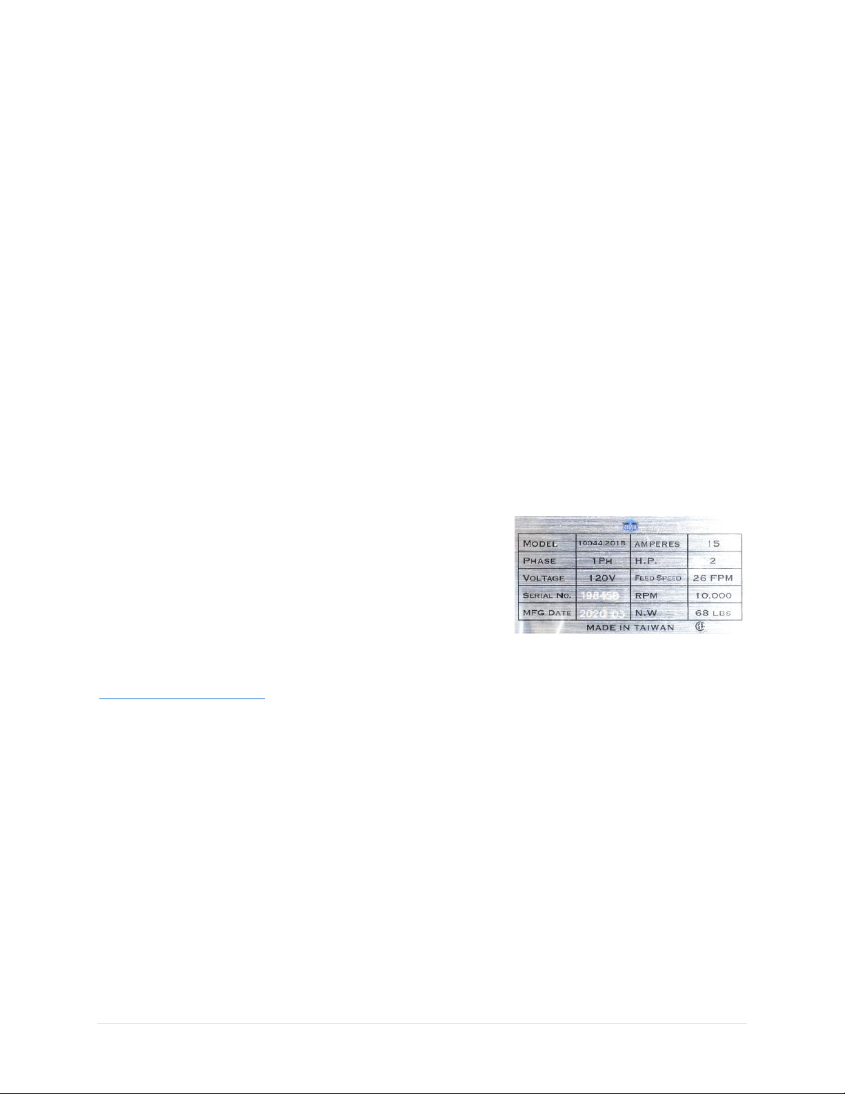
Identification ··········································· 9
Safety·····················································10
General Safety Guidelines·························10
Safety Guidelines Specific to Planer···········11
Electricals ···············································13
Minimum Circuit Size Required for Model
10044 Planer············································13
Grounding ················································13
Indoor Use Only ·······································13
Electrical Wiring ·······································13
Setup······················································15
Shop Preparation······································15
Space Requirement ·········································15
Electricals ························································15
Lighting····························································15
Safety Labels ···················································15
Dust Collection ················································15
Receiving··················································16
Unboxing ·························································17
Inventory·························································17
Waxing·····················································18
Assembly ·················································18
Dust Hood Installation·····································19
Cutterhead Elevation Crank Installation ·········19
DRO Battery Installation··································19
Dust Collection ·········································20
Bench Mounting (Optional) ······················20
Controls and Components ······················ 21
ON / OFF Switches····································21
Overloading Protection Reset Button ········21
Cutterhead Height Adjustment ·················21
Carriage Lock············································21
Digital Readout (DRO)·······························22
DRO Calibration········································22
Thickness Gauge·······································22
Depth Stops ·············································23
Components for Planing Wood ·················23
Test Run···················································24
Operation ·············································· 25
Step 1: Preparation···································25
Step 2: Setting Depth of Cut······················26
Step 3: Select Feed Direction·····················27
Step 4: Planing Wood to Desired Thickness27
Common Cutting Problems ·······················29
Snipe································································29
Chipping ··························································29
Indentation······················································29
Fuzzy Grain ······················································29
Accessories ············································ 30
Cutter Inserts ···········································30
Motor Carbon Brush·································30
Maintenance ········································· 31
Maintenance Schedule ·····························31
Instructions for Maintenance and
Adjustments ············································32
Service Cutterhead and Rotate Cutter Inserts 32

Inspect / Replace Poly V-Belt ··························33
Inspect / Replace Motor Carbon Brushes ·······34
Inspect / Adjust Extension Wing Elevation ·····35
Adjust Cutterhead Height Scale ······················35
Adjust Carriage Elevation Chain Tension ········36
Troubleshooting ·····································37
Wiring Diagram······································40
Parts List ················································41
Carriage and Cutterhead Assembly ···········41
Body and Base Assembly ··························43
Maintenance Record······························ 48
Notes····················································· 49
Warranty and Service····························· 50
Appendix ··············································· 51
US Standard – Metric Conversion Chart·····51

10044 Planer OLIVERMACHINERY.NET 5|Page
Introduction
Thank you for choosing Oliver! This manual contains important information on how to safely set up,
operate, and maintain this machine. Please take the time to read through this manual, and make sure you
understand all instructions.
While this manual may provide tips on optimizing the result of your workpiece, the manual is not intended
as a substitute for formal woodworking training. If you need to know how to safely complete a
woodworking task, please consult knowledgeable and qualified sources before proceeding further.
We made every effort to keep this manual up-to-date. Instructions, specifications, drawings, and
photographs in this manual should match the machine delivered. If you find any differences, or anything
that seems confusing in this manual, or some instructions are not available, please check our website for
an updated version:
WWW.OLIVERMACHINERY.NET/MANUALS
Alternatively, you can contact our technical support for help:
1-800-559-5065
Before calling, please note down the manufacture date and the
serial number of the machine. You can find the information on a
nameplate located on the back of the motor housing. This
information is needed to provide proper technical support, and to
determine if an updated manual is available for your machine.
Please let us know how well this manual serves you. If you have
any suggestions, please call the number above or email us at:
info@olivermachinery.net
We love to hear from our customers and make improvements.

6 | Page Oliver Machinery 10044 Planer
Specifications
Quick View
Model
10044 Planer
Stock Number
10044.201B
Motor
Universal Motor
2HP, 120V, 1Ph
Max. Stock Width
12-1/2”
Max Depth of Cut
3/64” (Full width)
5/64" (Stock less than 5” wide)
Dimensions
33-3/16”(L) x 23-1/4”(W) x 20-7/16”(H)
Footprint
14-1/4”(L) x 20-1/2”(W)
Fully Assembled Weight
68 lbs.
Warranty
1 Year (Motor and electronics)
2 Years (All other parts)
Product Dimensions
Width x Depth x Height (Fully Assembled)
33-3/16”(L) x 23-1/4”(W) x 20-7/16”(H)
Footprint
14-1/4” (L) x 20-1/2”(W)
Fully Assembled Weight
68 lbs.
Shipment Info
Type
Cardboard Box
Content
Planer with Included Accessories
Dimensions
25-1/4” (L) x 17-3/8”(W) x 21-3/4”(H)
Weight
72 lbs.
Approximate Setup Time
15 minutes
Must Ship Upright
YES
Stackable
YES
Electricals
Power Requirement
120V, 1Ph, 60Hz
Full Load Current Rating
15A
Recommended circuit size
20A
Power Switch Type
Magnetic switch with overload protection.
Connection Type
NEMA 5-15 Plug
Overload Protection
Equipped

10044 Planer OLIVERMACHINERY.NET 7|Page
Motor
Motor Type
Universal Motor
Horsepower
2HP
Speed
20000 RPM
Efficiency
50%
Power Transfer Mechanism
Poly V-belt and pulleys
Bearing type
Permanently sealed ball bearing
Planer Capacity and Performance
Maximum Stock Width
12-1/2”
Maximum Depth of Cut
5/64" (Stock less than 5” wide)
3/64”(Full Width)
Maximum Stock Thickness
6”
Minimum Stock Thickness
5/32”
Minimum Stock Length
5”
Feed Rate
26 FPM
Number of Cuts Per Square Inch
92
Cutterhead and Carriage
Cutterhead Type
Byrd Shelix® Cutterhead
Cutterhead Diameter
1-7/8”
Cutterhead Speed
10000 RPM
Number of Cutter Inserts
36
Number of Rows of Cutter Inserts
3
Cutter Insert Type
Four-sided, indexable carbide
Cutter Insert Diameters
15mm x 15mm x 2.5mm
Cutter Blade Angle
30 degree
Cutter Insert Screw Tensioning Torque
45 lbs.-inch
Infeed Roller Type
Rubber
Outfeed Roller Type
Rubber
Carriage Height Change Per Revolution of Crank
1/16”
Carriage Lock
Equipped
Measurements
Measurement Units
Inch/mm
Measurement Devices
Wixey Digital Readout
Digital Readout Resolution
1/32”/0.005”/0.1mm
Digital Readout Accuracy
+/- 1/500”/0.0025”/0.05mm
Additional Measurement Device
Carriage height scale
Depth Scale
Material Removal Gauge

8 | Page Oliver Machinery 10044 Planer
Table
Table Dimensions
33-3/16” x 12-1/2”
(With extension wings)
10-5/16” x 12-1/2”
(Without extension wings)
Material
Steel
Safety
Number of Dust Ports
1
Dust Port Size
4” (2.5” Adapter Included)
Minimum CFM Required
300 CFM
Sound Rating @ 2’ distance
103 dB
Others
Serial Number Location
On the back of the motor housing
Spare Parts Included
10 Byrd cutter inserts
Certification
CSA 175370
Country of Origin
Taiwan

10044 Planer OLIVERMACHINERY.NET 9|Page
Identification

10 | Page Oliver Machinery 10044 Planer
Safety
Oliver Machinery has made every attempt to provide a safe, reliable, easy-to-use piece of machinery.
Safety, however, is ultimately depending on the individual machine operator. Before operating this
machine, please become familiar with the following safety labels and guidelines.
DANGER
This indicates an imminently hazardous situation which, if not avoided, WILL cause
death or serious injury.
WARNING This means if the warning is not taken seriously, it CAN cause death or serious injury.
CAUTION This means if the precaution is not taken, it MAY cause minor or moderate injury.
IMPORTANT This is a tip for properly operating the machine to avoid machine damage.
General Safety Guidelines
1. FAMILIARIZE yourself with all safety instructions found in this manual. Know the limitations and
hazards associated with this machine. Do not operate or service this machine until you are properly
trained.
2. ELECTRICAL GROUNDING, when done properly, reduce the risk of electrocution, shocks, and fire.
Make certain that the machine frame is electrically grounded and that a ground lead is included in the
incoming electrical service. In cases where a cord and a plug are used, make certain that the grounding
plug connects to a suitable ground. Follow the grounding procedure indicated in the electrical code
of your area.
3. DISCONNECT the machine from power before performing any service, maintenance, or adjustments.
A machine under repair should be RED TAGGED to show it should not be used until the repair is
complete.
4. EYE PROTECTION: Always wear an approved safety face shield, goggles, or glasses that complies with
ANSI Z87.1 and CSA Z94.3 standards. Common eyeglasses are not safety glasses, and may not provide
adequate protection.
5. EAR PROTECTION: Use hearing protective devices where the noise exceeds the level of exposure
allowed in Section 1910.95 of the OSHA Regulations. When in doubt, use it.
6. OTHER PERSONAL PROTECTION: Before operating this machine, remove tie, rings, watch, and other
jewelry. Roll up sleeves above elbows. Remove all loose outer clothing and confine long hair. Wear
professional work boots to protect your feet from injuries and slippage. Do not wear gloves unless it
is instructed to perform a particular step(s) in the manual.
7. GUARDS: Keep machine guards in place for all applicable operations. If any guards are removed for
maintenance, DO NOT OPERATE the machine until all guards are reinstalled.

10044 Planer OLIVERMACHINERY.NET 11 |Page
8. WORKPLACE SAFETY: Keep the floor around the machine clean. Scrap material, sawdust, oil, and
other liquids increase the risk of tripping or slipping. Be sure to clean up the table before starting the
machine. Make certain the work area is well lighted and that a proper exhaust system is used to
minimize dust. Use anti-skid floor strips on the floor area where the operator normally stands and
mark off the machine work area. Provide adequate workspace around the machine.
9. ACCESS CONTROL should be enforced so only trained personnel can access the work area and operate
the machine. Use childproof power switch when applicable.
10. STAY ALERT at all times. Do not operate this machine while under the influence of drugs/alcohol, or
when not feeling well.
11. NEVER STAND ON MACHINE.
12. REPLACEMENT PARTS: Use only genuine Oliver Machinery replacement parts and accessories
recommended for this machine. Generic parts made by other manufacturers may create a safety
hazard and WILL void the factory warranty and other guarantees.
13. PROPER USE: Do not use this machine for anything other than its intended use. If used for other
purposes, Oliver Machinery disclaims any real or implied warranty and holds itself harmless for any
injury or damage which may result from that use.
Safety Guidelines Specific to Planer
Before Work Begins:
1. USE ONLY NATURAL, SOLID WOOD. Do not plane any material such as plywood, MDF, OSB, laminate,
or anything that can disintegrate during operation. Do not plane treated lumber or anything that
contains harmful chemicals, as this will spread wood dust that contains such harmful chemicals. Do
not attempt to plane any workpiece with loose knots or with any other foreign materials.
2. CHECK CUTTER INSERTS:Make sure cutter inserts are sharp, clean, and free from damages. Forcing
dull/damaged cutter inserts to work invites accidents and impacts finish quality. Use the
recommended amount of torque to securely fasten all inserts onto the cutterhead.
3. SERVICING CUTTER INSERTS: Wear heavy-duty leather gloves to protect your hands when installing
new cutter inserts or rotating the existing ones. Ensure the cutterhead is thoroughly clean before
installing the insert. Debris between the cutter insert and its seat can create uneven pressure, causing
the insert to break, and body injuries may occur.
4. SUPPORT LONG WORKPIECE with auxiliary stock feeding rollers/tables. This will help to avoid injuries
and improve the quality of the finish. Bolt down machine to prevent tipping.

12 | Page Oliver Machinery 10044 Planer
When Planing:
1. DUST COLLECTION SYSTEM is required for this planer. Please make sure the system is on and provide
enough suction before starting the planer.
2. KICKBACK happens when a workpiece is ejected, usually towards the infeed side of the planer, during
operation. This can cause serious injuries or even death. The operator should be cautious about
possible kickbacks.
•ALWAYS wear proper protection devices and stay away from the line-of-fire to avoid kickback-
related accidents.
•NEVER look inside the planer during operation.
•NEVER plane boards that are shorter than 5” as mentioned in the specifications.
3. PROPER WORKPIECE FEEDING avoids kickback. Never start the machine with the workpiece engaging
the cutterhead. Never start feeding until the planer has reached its full speed. Ensure feed rollers
apply an adequate amount of pressure on the workpiece.
•NEVER force a workpiece through the planer. Make adjustments as needed.
•ONLY plane one board at a time.
•For twisted workpieces, face joint with a jointer before thickness planing.
4. STUCK WORKPIECE should be removed only after the planer is powered off, and the cutterhead
comes to a complete stop. Do not use hands or push sticks to force-feed a workpiece through the
planer, as it can result in severe injuries and/or machine damage.
5. DEPTH OF CUT SETTINGS: Do not force the planer to exceed its maximum depth of cut capacity found
in the specification. Failing to comply can cause machine damage and injuries. Reduce the depth of
cut for hard materials as that increases the planer’s workload.
After Operation
1. STOP THE MACHINE if the operator leaves the machine for any reason.
2. WAIT until the machine comes to a complete stop.
3. CLEAN UP work area before departure.

10044 Planer OLIVERMACHINERY.NET 13 |Page
Electricals
WARNING
All electrical work must be done by a qualified electrician and must meet the
electrical code in your area.
Minimum Circuit Size Required for Model 10044 Planer
Stock Number
Minimum Circuit Size Required
10044.201B
20A
Please ensure the electrical circuit for this machine meets the minimum circuit size requirement. The
minimum circuit size requirement applies to a dedicated circuit that provides power to one 10044 Planer.
If more items are sharing the same circuit, consult a qualified electrician to ensure the designated circuit
is properly sized for safe operation.
If a circuit is available, but not meeting the minimum circuit size requirement listed above, a new circuit
must be installed for this machine.
Grounding
WARNING Improper grounding can cause electric shock, fire, and equipment damage.
Proper grounding reduces the risk to the operator in the event of electrical malfunction or breakdown.
This machine must be connected to the grounding conductor when available, and all grounding
connections must meet or exceed the electrical code requirements in your area. Furthermore, all grounds
must be verified and must meet or exceed the electrical requirement of the machine. If grounding is not
available, consider the use of a GFCI protection device as an alternative, if this complies with the electric
code in your area.
Indoor Use Only
This machine is designed for indoor use only. Operating this machine outdoor increases its exposure to
moisture, which in turn increases the risk of electric shock.
Electrical Wiring
This machine is pre-wired for 120V with a cord and plug. Use of extension cord is not recommended. If
you need to use an extension cord to connect to a power source, select a durable cord type with a high-
temperature rating (90C° or above). Use the minimum amount of extension cord as needed.

14 | Page Oliver Machinery 10044 Planer
Minimum cord size (AWG) required based on amperage draw and length of the cord:
Amps
Power Cord Length
25 feet
50 feet
75 feet
100 feet
> 100 feet
< 5
16
14
14
14
NR
5 to 8
14
14
14
12
8 to 12
14
14
12
10
12 to 15
12
12
10
10
15 to 20
10
10
10
NR
21 to 30
10
NR
NR
NR
*NR: Not Recommended
WARNING
Use properly sized wires that meet or exceed the power requirement of your
machine. Using undersized wires may cause overheating and increase the risk of fire
and machine damage.

10044 Planer OLIVERMACHINERY.NET 15 |Page
Setup
Shop Preparation
Space Requirement
The dimensions of this machine are 33-3/16”(L) x 23-
1/4”(W). You will need additional spaces for
manipulating your workpiece, electrical connection,
and dust collection.
Electricals
If you plan to install this machine in a permanent
location, make sure a properly sized circuit and
electrical outlet are available nearby. Please refer to
section “Electricals” in this manual for details
regarding electrical requirements.
Lighting
Adequate lighting is needed for operating this machine. Overhead, non-glare lighting should be installed.
Safety Labels
If this machine introduces a new safety hazard to your workplace, display proper warning signs in a highly
visible location(s).
Dust Collection
Wood dust created by this planer is a health hazard. Position this planer in a spot where it has access to a
dust collection system.
Dust masks should be available for using the planer.
CAUTION
Use a dust collection system that is rated above
300 CFM. Doing so imp
roves air
quality in the workplace, and
prevents the machine from jamming.
Piping of dust collection system introduces additional air resistance and decreases
the effective CFM measured at the dust ports. Ensure
there is significant suction at
the dust port, so
dust and debris can be effectively removed from the machine.

16 | Page Oliver Machinery 10044 Planer
Receiving
If this planer is delivered to you, please check for any significant damages on the packaging before signing
the delivery confirmation.
This machine has a shipping weight of 72 lbs., and a net weight of 68 lbs. Please be sure help is available
to move the machine to its final location.
WARNING
10044 Planer has a gross weight of 72 lbs. and a net weight of 68 lbs.
Safe moving techniques and proper lifting equipment are required, or serious
personal injury may occur.
WARNING
Do not lift your shipment by the strap. They are not designed to hold the total
weight of your shipment. They may snap without warning and cause serious injury
and machine damage.
Straps may spring back violently when released and cause injury. Always wear
safety goggles and gloves when removing straps.
IMPORTANT If items are damaged, please call us immediately at 1-800-559-5065

10044 Planer OLIVERMACHINERY.NET 17 |Page
Unboxing
Inside the box, you should find a planer, a cutterhead elevation crank, and a box that contains all loose
parts and accessories.
Inventory
Carefully unwrap the packaging and make sure all components are included in the shipment. Layout all
items received and inventory them.

18 | Page Oliver Machinery 10044 Planer
Item
Description
Quantity
1
2.5” Dust port adapter
1
2
Mounting hardware for dust hood
•Screw
•
Washer
3 each
3
Dust hood with 4” dust port
1
4
Cutterhead elevation crank and mounting screw
1 each
5
Cutter insert installation instructions from Byrd Tool
1
6
1/4" Spinner handle and
T25 Torx bit socket (1/4 in. Drive)
1 each
7
Spare Byrd cutter inserts
10
8
AAA battery for digital readout
2
NOTICE: If you cannot find an item in the list above, please check if it is still attached to the packaging.
Occasionally the item may have been pre-installed in the factory. See section “Parts List” to check if a
component is included or installed.
NOTICE: This machine comes with various standard sized, non-proprietary parts. If any of these parts are
missing, we are happy to deliver them to you. To have the machine up and running as soon as possible,
you can also find these parts at your local hardware store.
Additional Items Recommended for Machine Assembly
Item
Purpose
Safety Glasses
Protection
Disposable Gloves
Protection
Straight edge
Check alignments.
¼” Drive Torque Wrench
Cutter inserts installation and for checking Torx screw tension (45 lbs.-
inch).
Waxing
The surfaces of the steel planer bed and extension wings have a low resistance finish. To minimize stock
feeding resistance, it is recommended to wax these surfaces with paste wax before first use, and routinely
thereafter.
Assembly
This planer is mostly assembled in the factory. There are a few more items to set up before the machine
is ready for a test run:
1. Install the dust hood.
2. Install the cutterhead elevation crank.
3. Install the DRO battery.
4. Connect the planer to a dust collection system.
The approximate time for cleaning and assembly is approximately 15 minutes.

10044 Planer OLIVERMACHINERY.NET 19 |Page
Dust Hood Installation
1. Remove cardboard packaging that supports
dust hood during shipment.
2. Attach dust hood onto the cutterhead cover
plate.
3. Use the provided mounting screws and
washers to secure the dust hood at the
bottom and on each side.
Cutterhead Elevation Crank Installation
1. Install the crank. Make sure flat surfaces on
the crank and the shaft are aligned.
2. Secure the crank with a T-30 Torx screw that
comes with the package. A T-30 Torx wrench
can be pulled out from the top panel for this
task.
DRO Battery Installation
1. Remove the battery cover and install two
AAA sized batteries. Reinstall the cover
when done.

20 | Page Oliver Machinery 10044 Planer
Dust Collection
This wood planer can generate a lot of wood shavings and dust. Although this planer is equipped with an
internal dust blower, it is still a good idea to connect this planer to a dust collection system, so all dust
and wood chips can be effectively removed and contained.
The minimum CFM requirement for this planer is 300 CFM at the dust port, which means your dust
collection system should have a rating greater than 300 CFM, as air friction and leakage reduce effective
CFM at the dust port.
This planer comes with a 2-1/2” dust port adapter which is compatible with a standard-sized vacuum
hose. It is possible to connect this planer to a vacuum with good suction for light-duty tasks.
Bench Mounting (Optional)
Mounting this planer on a stable surface prevents it from tipping when planing long stock. The diagram
below has the measurements of the planer base and the mounting holes. Using four 9/16” bolts for
mounting provides maximum strength and stability. Alternatively, there is another set of four mounting
holes that accept screws up to size #10.
IMPORTANT
Running this planer without a dust collection system, or using a dust collection
system with inadequate suction, may cause dust and shavings to accumulate
inside the planer. This can damage the machine and cause other hazardous
situations. Check your dust collection system regularly to make sure it is not
jammed or filled up.
When using this planer without a dust collection system, make sure wood chips
are not getting accumulated inside the machine. Clean planer frequently.
Table of contents
Other Oliver Power Tools manuals

Oliver
Oliver 4265C Instruction Manual

Oliver
Oliver 4260 User manual

Oliver
Oliver 4705 User manual

Oliver
Oliver M1013 User manual

Oliver
Oliver 4230 User manual

Oliver
Oliver 0006 User manual

Oliver
Oliver 4265 User manual

Oliver
Oliver 10062 User manual

Oliver
Oliver 7660.002 User manual

Oliver
Oliver 4705 User manual