Oliver 4235 User manual


PROP 65 NOTICE
WARNING: Drilling, sawing, sanding, or machining wood products can expose you to wood dust,
and/or other chemicals that are known to the State of California to cause cancer, birth defects,
or other reproductive harm.
Some examples of these chemicals are:
•Lead from lead-based paints.
•Crystalline silica from bricks, cement, and other masonry products.
•Arsenic and chromium from chemically treated lumber.
Avoid inhaling wood dust and other harmful chemicals. Use a dust mask and/or other safety
devices for personal protection.
For more information go to http://www.P65Warnings.ca.gov/wood
READ AND UNDERSTAND ALL INSTRUCTIONS IN THIS MANUAL BEFORE
ATTEMPTING TO ASSEMBLE OR OPERATE THE MACHINE.
FOLLOW THE INSTRUCTIONS AND THINK SAFETY!
THE OWNER OF THIS MACHINE IS SOLELY RESPONSIBLE FOR THE SAFETY OF ANYONE USING
THIS MACHINE. SUCH RESPONSIBILITY INCLUDES BUT NOT LIMITED TO:
•PROPER ASSEMBLY, OPERATION, INSPECTION, MAINTENANCE, AND RELOCATION OF
THE MACHINE.
•PROPER TRAINING FOR THE OPERATORS AND ENSURES THIS MANUAL IS AVAILABLE
AT ALL TIMES.
•USAGE AUTHORIZATION.
•USAGE OF SAFETY AND PROTECTION DEVICE.
OLIVER MACHINERY DISCLAIMS ANY LIABILITY FOR MACHINES THAT HAVE BEEN ALTERED OR
ABUSED. OLIVER MACHINERY RESERVES THE RIGHT TO EFFECT AT ANY TIME, WITHOUT PRIOR
NOTICE, THOSE ALTERATIONS TO PARTS, FITTINGS, AND ACCESSORY EQUIPMENT WHICH THEY
MAY DEEM NECESSARY FOR ANY REASON WHATSOEVER.
** SAVE THIS MANUAL FOR FUTURE REFERENCES. **

Table of Contents
Introduction············································· 5
Specifications ·········································· 6
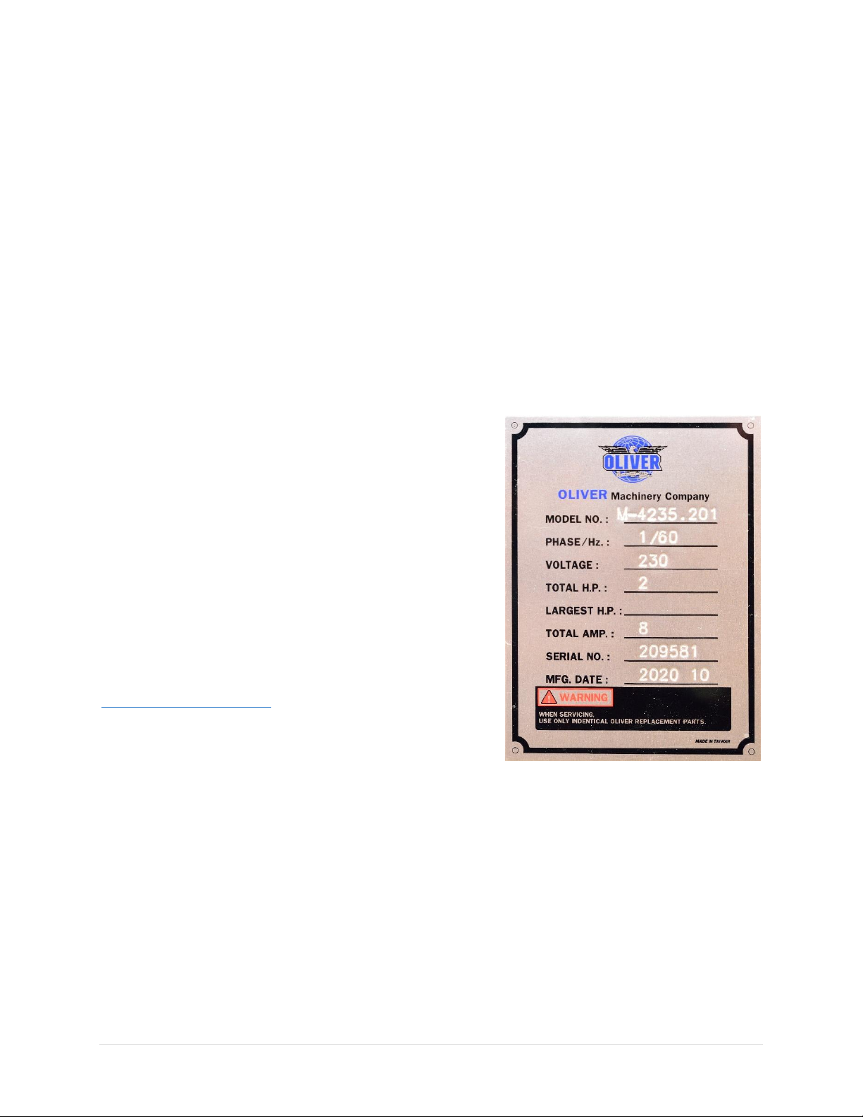
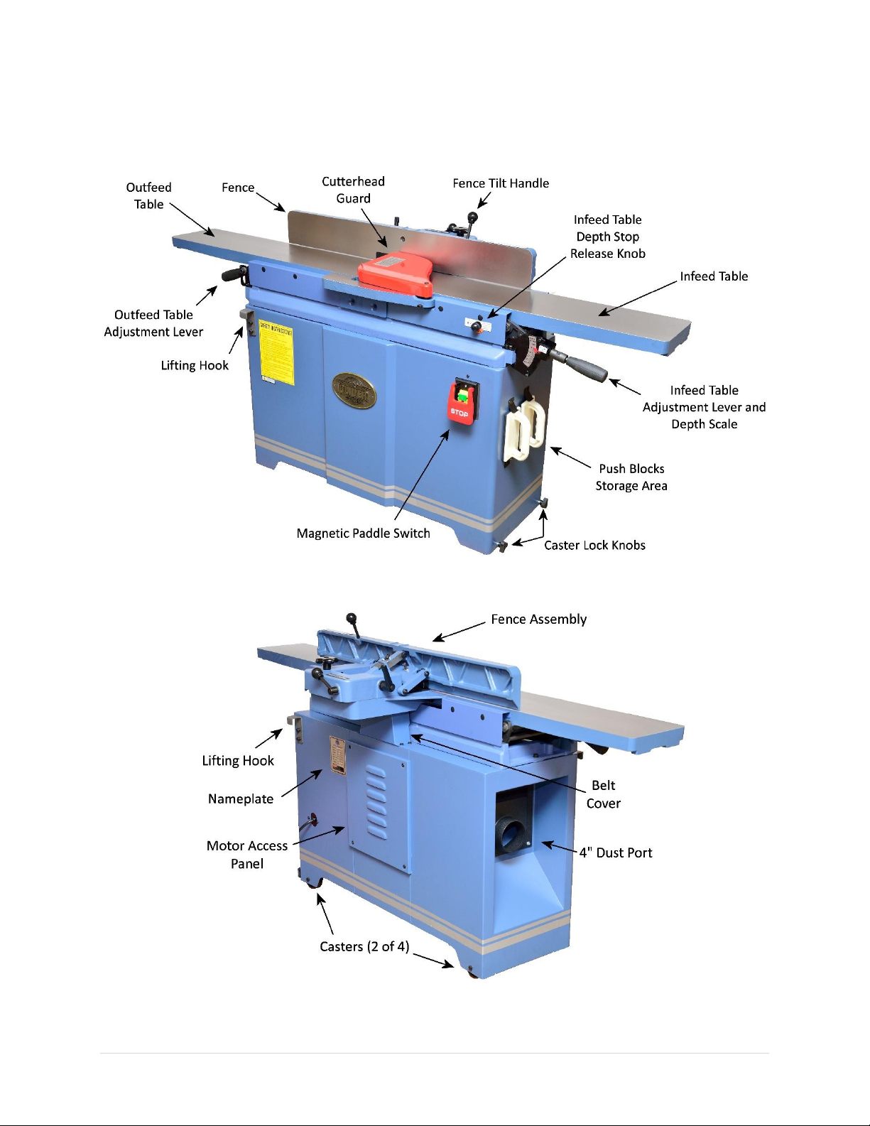
Identification ··········································· 9
Safety·····················································11
General Safety Guidelines·························11
Safety Guidelines Specific to Jointer··········12
Electricals ···············································14
Minimum Circuit Size Required for Model
4235 Jointer ·············································14
Grounding················································14
Electrical Wiring ·······································14
Setup······················································16
Shop Preparation······································16
Space Requirement ·········································16
Load Limits ······················································16
Electricals ························································16
Lighting····························································16
Safety Labels ···················································16
Dust Collection ················································16
Receiving··················································17
Cleaning···················································19
Assembly ·················································20
Dust Collection·········································22
Controls and Components ·······················23
Powerswitch ············································23
Infeed Table Adjustment ··························23
Infeed Table Depth Stop Knob ··················23
Outfeed Table Height Adjustment·············24
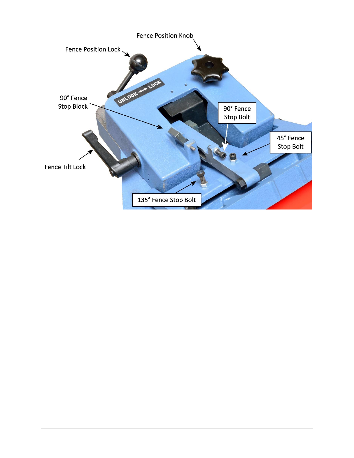
Fence ·······················································25
Test Run···················································26
Operation···············································27
Preparation··············································27
Inspect Wood Grain··································28
Squaring Stock··········································28
Surface Planing·········································29
Edge Jointing············································31
Beveling···················································31
Rabbet Cutting ·········································32
Common Cutting Problems ·······················33
Snipe································································33
Chipping ··························································33
Fuzzy Grain······················································33
Accessories ············································ 34
Maintenance ········································· 35
Maintenance Schedule ·····························35
Inspect / Adjust Jointer Tables ··················36
Inspect Outfeed Table Height ·························36
Adjust Outfeed Table Height···························36
Inspect Outfeed Table Parallelism ··················37
Inspect Infeed Table········································37
Adjust Table Parallelism/Coplanarity ··············38
Infeed Table Adjustments ·······························40
Infeed Table Depth Stop Adjustments ············41
Rotate / Replace Cutter Inserts ·················42
Adjust Fence Positive Stops ······················43
Adjust Belt Tension···································45
Align Belt Pulleys······································46
Troubleshooting····································· 47
Mechanical / Electrical Issues····················47
Operation / Quality-Related Issues ···········48
Wiring Diagram ····································· 50
Parts List················································ 51
Maintenance Record······························ 60
Notes····················································· 61
Warranty and Service····························· 62
Appendix ··············································· 63
US Standard –Metric Conversion Chart·····63

4235 Jointer OLIVERMACHINERY.NET 5|Page
Introduction
Thank you for choosing Oliver! This manual contains important information on how to safely set up,
operate, and maintain this machine. Please take the time to read through this manual, and make sure you
understand all instructions.
While this manual may provide tips on optimizing the result of your workpiece, the manual is not intended
as a substitute for formal woodworking training. If you need to know how to safely complete a
woodworking task, please consult knowledgeable and qualified sources before proceeding further.
We made every effort to keep this manual up-to-date. Instructions, specifications, drawings, and
photographs in this manual should match the machine delivered. If you find any differences, or anything
that seems confusing in this manual, or some instructions are not available, please check our website for
an updated version:
WWW.OLIVERMACHINERY.NET/MANUALS
Alternatively, you can contact our technical support for help:
1-800-559-5065
Before calling, please note down the manufacture date and the
serial number of the machine. You can find the information on
a nameplate located on the back of the machine. This
information is needed to provide proper technical support,
and to determine if an updated manual is available for your
machine.
Please let us know how well this manual serves you. If you have
any suggestions, please call the number above or email us at:
info@olivermachinery.net
We love to hear from our customers and make improvements.

6 | Page Oliver Machinery 4235 Jointer
Specifications
Quick View
Model
4235 Jointer
Stock Number
4235.201
Motor
TEFC Induction Motor
2HP, 230V, 1Ph
Jointer Size
8”
Max. Depth of Cut (Jointing)
1/8"
Max. Depth of Cut (Rabbeting)
1/2”
Bevel Joining
45°-135° (With quick stops at 45°, 90°, 135°)
Dimensions
72-1/4”(L) x 25”(W) x 39-1/2”(H)
Footprint
39-1/4”(L) x 14-1/2”(W)
Fully Assembled Weight
352 lbs.
Warranty
1 Year (Motor and electronics)
2 Years (All other parts)
Product Dimensions
Jointer Fully Assembled
72-1/4”(L) x 25”(W) x 39-1/2”(H)
Footprint
39-1/4”(L) x 14-1/2”(W)
Fully Assembled Weight
352 lbs.
Shipment Info
Type
Wood crate with skid
Content
Jointer with included accessories
Dimensions
75-3/4”(L) x 25-1/4”(W) x 42”(H)
Weight
489 lbs.
Approximate Setup Time
45 minutes
Must Ship Upright
YES
Stackable
NO
Electricals
Power Requirement
230V, 1Ph, 60Hz
Full Load Current Rating
8A
Recommended circuit size
15A
Power Switch Type
Magnetic paddle switch
Connection Type
NEMA 6-15 Plug with 7’14 AWG Cord

4235 Jointer OLIVERMACHINERY.NET 7|Page
Motor
Motor Type
TEFC Induction Motor
Horsepower
2HP
Speed
3450 RPM
Efficiency
82.8%
Power Factor
95.4%
Power Transfer Mechanism
Poly V-belt and pulleys
Bearing type
Permanently sealed ball bearing
Jointer Capacity and Performance
Maximum Stock Width
8”
Maximum Depth of Cut for Jointing
1/8"
Maximum Depth of Cut for Rabbeting
1/2”
Minimum Stock Thickness
3/4”
Minimum Stock Length
10”
Fence
Dimensions
38-1/8”(L) x 4-3/4”(H)
Fence Tilt
45° - 135°
Fence Stops
45°, 90°, 135°
Material
Precision ground cast iron
Cutterhead
Cutterhead Type
Helical
Cutterhead Diameter
3-5/64”
Cutterhead Speed
5500 RPM
Number of Cutter Inserts
36
Number of Rows of Cutter Inserts
4
Cutter Insert Type
Four-sided, indexable carbide
Cutter Insert Diameters
15mm x 15mm x 2.5mm
Cutter Blade Angle
30 degree
Cutter Insert Screw Tensioning Torque
52-60 lb-in
Table
Table Dimensions
72-1/4”(L) x 8”(W)
Table Height Above Ground
31-1/8”
Table Lifting / Adjustment Mechanism
Parallelogram
Material
Precision ground cast iron

8 | Page Oliver Machinery 4235 Jointer
Measurements
Measurement Unit
Inch
Measurement Devices
Depth Scale
Safety
Number of Dust Ports
1
Dust Port Size
4”
Minimum CFM Required
500 CFM
Sound Rating @ 2’ distance
83 dB
Others
Serial Number Location
On the back of the machine.
Spare Parts Included
Five cutter inserts and compatible Torx screws.
Certification
CSA 175370
Country of Origin
Taiwan

4235 Jointer OLIVERMACHINERY.NET 9|Page
Identification

10 | Page Oliver Machinery 4235 Jointer

4235 Jointer OLIVERMACHINERY.NET 11 |Page
Safety
Oliver Machinery has made every attempt to provide a safe, reliable, easy-to-use piece of machinery.
Safety, however, is ultimately depending on the individual machine operator. Before operating this
machine, please become familiar with the following safety labels and guidelines.
DANGER
This indicates an imminently hazardous situation which, if not avoided, WILL cause
death or serious injury.
WARNING
This means if the warning is not taken seriously, it CAN cause death or serious injury.
CAUTION
This means if the precaution is not taken, it MAY cause minor or moderate injury.
IMPORTANT
This is a tip for properly operating the machine to avoid machine damage.
General Safety Guidelines
1. FAMILIARIZE yourself with all safety instructions found in this manual. Know the limitations and
hazards associated with this machine. Do not operate/service this machine until you are properly
trained.
2. ELECTRICAL GROUNDING, when done properly, reduce the risk of electrocution, shocks, and fire.
Make certain that the machine frame is electrically grounded and that a ground lead is included in the
incoming electrical service. In cases where a cord and a plug are used, make certain that the grounding
plug connects to a suitable ground. Follow the grounding procedure indicated in the electrical code
of your area.
3. DISCONNECT the machine from power before performing any service, maintenance, or adjustments.
A machine under repair should be RED TAGGED to show it should not be used until the repair is
complete.
4. EYE PROTECTION: Always wear an approved safety face shield, goggles, or glasses that complies with
ANSI Z87.1 and CSA Z94.3 standards. Common eyeglasses are not safety glasses, and may not provide
adequate protection.
5. EAR PROTECTION: Use hearing protective devices where the noise exceeds the level of exposure
allowed in Section 1910.95 of the OSHA Regulations. When in doubt, use it.
6. OTHER PERSONAL PROTECTION: Before the operation, remove tie, rings, watch, and other jewelry.
Roll up sleeves above elbows. Remove all loose outer clothing and confine long hair. Protective
footwear should be used. Do not wear gloves when operating woodworking machinery. However, it
is recommended to wear protective gloves when servicing machines.
7. GUARDS: Keep machine guards in place for all applicable operations. If any guards are removed for
maintenance, DO NOT OPERATE the machine until all guards are reinstalled. Check clearance between
the guards and the cutter before starting the machine.
8. WORKPLACE SAFETY: Keep the floor around the machine clean. Scrap material, sawdust, oil, and
other liquids increase the risk of tripping or slipping. Be sure to clean up the table before starting the
machine. Make certain the work area is well lighted and that a proper exhaust system is used to

12 | Page Oliver Machinery 4235 Jointer
minimize dust. Use anti-skid floor strips on the floor area where the operator normally stands and
mark off the machine work area. Provide adequate workspace around the machine.
9. ACCESS CONTROL should be enforced so only trained personnel can access the work area and operate
the machine. Use a childproof power switch when applicable.
10. STAY ALERT at all times. Do not operate this machine while under the influence of drugs/alcohol, or
when not feeling well.
11. NEVER STAND ON MACHINE. This prevents injuries from tipping related accidents and accidental
contacts with cutters.
12. REPLACEMENT PARTS: Use only genuine Oliver Machinery replacement parts and accessories
recommended for this machine. Generic parts made by other manufacturers may create a safety
hazard and WILL void the factory warranty and other guarantees.
13. PROPER USE: Do not use this machine for anything other than its intended use. If used for other
purposes, Oliver Machinery disclaims any real or implied warranty and holds itself harmless for any
injury or damage which may result from that use.
Safety Guidelines Specific to Jointer
Before Work Begins:
1. USE ONLY NATURAL, SOLID WOOD. Do not joint any material such as plywood, MDF, OSB, laminate,
or anything that can disintegrate during operation. Do not joint treated lumber or anything that
contains harmful chemicals, as this will spread wood dust that contains such harmful chemicals. Do
not attempt to joint any workpiece with loose knots or with any other foreign materials.
2. CHECK CUTTER INSERTS: Make sure cutter inserts are sharp, clean, and free from damages. Forcing
dull/damaged cutter inserts to work invites accidents and impacts finish quality. Use the
recommended amount of torque to securely fasten all inserts onto the cutterhead.
3. SERVICING CUTTER INSERTS: Wear heavy-duty leather gloves to protect your hands when installing
new cutter inserts or rotating the existing ones. Ensure the cutterhead is thoroughly cleaned before
installing the insert. Debris between the cutter insert and the platform can create uneven pressure,
causing the insert to break, and body injuries may occur.
4. CHECK CUTTERHEAD GUARD: Make sure the cutterhead guard is installed and is properly tensioned.
The cutterhead guard should spring back and push against the fence after it is rotated away and
released.
5. CHECK OUTFEED TABLE HEIGHT AND ALIGNMENT to avoid a workpiece getting stuck while feeding.
The outfeed table should be flush with or slightly below the cutting arc of the cutterhead.
6. CHECK DEPTH OF CUT SETTING. The maximum depth of cut for each pass is 1/8”.
7. SUPPORT LONG WORKPIECE with auxiliary stock feeding rollers/tables. This helps to avoid injuries
and improves the quality of the finish.

4235 Jointer OLIVERMACHINERY.NET 13 |Page
When Jointing:
1. DUST COLLECTION SYSTEM is required for this jointer. Please make sure the system is on and provide
enough suction before starting the jointer.
2. KICKBACK happens when a workpiece is ejected at high speed during operation. Kickback projectiles
can cause serious injuries or even death. Sudden movements of the workpiece from kickback can also
cause hands or other body parts to get pulled into the cutterhead. The operator should be cautious
at all times about possible kickback.
3. PROPER STOCK FEEDING reduces the chance of kickback. NEVER start the machine with anything
engaging the cutterhead. NEVER start feeding until the jointer has reached its full speed. Use the right
amount of downward pressure and forward force for feeding.
4. INSPECT WORKPIECE. Ensure the workpiece is free from nails, loose knots, and other foreign
material. Use a metal detector to scan for metal objects as appropriate.
5. NEVER joint material shorter than 10”, thinner than 3/4”, or narrower than 2”. This reduces the risk
of accidental contact with the cutterhead.
6. NEVER rabbet material with width or thickness less than 3/4”, or shorter than 10”.
7. FOLLOW THE 3-INCH RULE. Always use push blocks when jointing materials less than 3” in thickness
or width. Keep your hands at least three inches away from the cutterhead at all times when the
machine is running.
8. CUPPED WORKPIECE should be jointed with the cupped side facing down. This prevents the
workpiece from rocking when feeding through the jointer.
9. PAY ATTENTION TO THE GRAIN DIRECTION. Always cut WITH the grain whenever possible. Jointing
against or across the grain, or jointing the end grain increases the chance of tear-out and kickback.
After Operation
1. STOP THE MACHINE if the operator leaves the machine for any reason.
2. WAIT until the machine comes to a complete stop.
3. CLEAN UP and LOCK POWER SWITCH before departure.

14 | Page Oliver Machinery 4235 Jointer
Electricals
WARNING
All electrical work must be done by a qualified electrician and must meet the
electrical code in your area.
Minimum Circuit Size Required for Model 4235 Jointer
Stock Number
Minimum Circuit Size Required
4235.201
15A8A
Please ensure the electrical circuit for this machine meets the minimum circuit size requirement. The
minimum circuit size requirement applies to a dedicated circuit that provides power to one 4235 Jointer.
If more machines are sharing the same circuit, consult a qualified electrician to ensure the designated
circuit is properly sized for safe operation.
If a circuit is available, but not meeting the minimum circuit size requirement listed above, a new circuit
must be installed for this machine.
Grounding
WARNING
Improper grounding can cause electric shock, fire, and equipment damage.
Proper grounding reduces the risk to the operator in the event of electrical malfunction or breakdown.
This machine must be connected to the grounding conductor when available, and all grounding
connections must meet or exceed the electrical code requirements in your area. Furthermore, all grounds
must be verified and must meet or exceed the electrical requirement of the machine. If grounding is not
available, consider the use of a GFCI protection device as an alternative, if this complies with the electric
code in your area.
Electrical Wiring
This machine is pre-wired for 230V with a cord and a NEMA 6-15 plug. Please refer to the section “Wiring
Diagram” on page 50 for rewiring this machine for 230V operations. A 230V compatible plug is required.
Use of extension cord is not recommended. If you need to use an extension cord to connect to a power
source, select a durable cord type with high-temperature rating (90C° or above). Use the minimum
amount of extension cord as needed.

4235 Jointer OLIVERMACHINERY.NET 15 |Page
Minimum cord size (AWG) required based on amperage draw and length of the cord:
Amps
Power Cord Length
25 feet
50 feet
75 feet
100 feet
> 100 feet
< 5
16
14
14
14
NR
5 to 8
14
14
14
12
8 to 12
14
14
12
10
12 to 15
12
12
10
10
15 to 20
10
10
10
NR
21 to 30
10
NR
NR
NR
*NR: Not Recommended
WARNING
Use properly sized wires that meet or exceed the power requirement of your
machine. Using undersized wires may cause overheating and increase the risk of fire
and machine damage.

16 | Page Oliver Machinery 4235 Jointer
Setup
Shop Preparation
Space Requirement
The dimensions of this machine are 72-1/4”(L) x
25”(W). You will need additional spaces for
manipulating your workpiece, electrical connection,
and dust collection.
Load Limits
This machine has a shipping weight of 489 lbs., and a net weight of 352 lbs. Please ensure all lifting tools
and building structures have adequate load capacity, for transporting and supporting the total weight of
this machine, the operator, and related items.
Electricals
Ensure a properly sized circuit and an electrical terminal are available nearby the machine. If the machine
is to be hardwired, there must be a readily accessible power disconnect nearby, so that the machine can
be disconnected from the power source for servicing and adjustments. If the machine is to be connected
with a cord and a plug, please ensure a matching outlet is installed nearby the machine.
Please refer to the previous chapter “Electricals”on page 14 for details regarding electrical requirements.
Lighting
Adequate lighting is needed for operating this machine. Overhead, non-glare lighting should be installed.
Safety Labels
If this machine introduces a new safety hazard to your workplace, display proper warning signs in a highly
visible location(s).
Dust Collection
Wood dust created by this jointer is a health hazard. Connect a dust collection system to this machine.
Check air suction regularly to ensure the pipes are not jammed.
Dust masks should be available for using the jointer.
CAUTION
Use a dust collection system that is rated above 500 CFM. Doing so improves air
quality in the workplace, and prevents the machine from jamming.
Piping of dustcollectionsystem introduces additional air resistance and decreases
the effective CFM measured at the dust ports. Ensure there is significant suction
at the dust port, so dust and debris can be effectively removed from the machine.

4235 Jointer OLIVERMACHINERY.NET 17 |Page
Receiving
Your shipment should come with one wood crate. Upon receiving your shipment, check for any significant
damages before signing the delivery confirmation.
Moving Machine into the Shop
Your machine will be delivered by freight service, and it will be left outside of your workshop by default.
On the day of delivery, please be sure help is available to move the machine to its final location.
WARNING
4235 Jointer has a gross weight of 489 lbs. and a net weight of 352 lbs.
Safe moving techniques and proper lifting equipment are required, or serious
personal injury may occur.
WARNING
Your shipment may be secured by the straps. Do not lift your shipment by the
strap. They are not designed to hold the total weight of your shipment. They may
snap without warning and cause serious injury and machine damage.
Always wear safety goggles and gloves when removing straps, as they may spring
back violently when released and cause injury.
Unboxing
The crate contains a jointer that is mostly assembled. It also contains two paper boxes with loose parts
and accessories. Everything is covered by a plastic bag.
IMPORTANT
If items are damaged, please call us immediately at 1-800-559-5065
IMPORTANT
Install the provided lifting hooks and use them for lifting the jointer. Do not lift the
machine by the tables as it may alter the alignment of the tables.

18 | Page Oliver Machinery 4235 Jointer
Inventory
Carefully unwrap the packaging and inventory the items received:
Item
Description
Quantity
1
T-Handle torx drivers (T-25)
2
2
Spare Cutter Inserts
Spare Torx Screws
5
10
3
8/10 mm Open End Wrench
1
4
11/13 mm Open End Wrench
1
5
Metric hex wrench set (3mm, 6mm)
1
6
Push blocks
2
7
Cutterhead guard
1
8
Lifting Hooks
Cap Screws
Spring Washers
2
4
4
9
Caster Lock Knobs
2
NOTICE: If you cannot find an item in the list above, please check if it is still attached to the packaging or
inside the cabinet. Occasionally the item may have been pre-installed in the factory. See section “Parts
List” to check if a component is included or installed.
NOTICE: This machine comes with various standard-sized, non-proprietary parts. If any of these parts are
missing, we are happy to deliver them to you. To have the machine up and running as soon as possible,
you can also find these parts at your local hardware store.

4235 Jointer OLIVERMACHINERY.NET 19 |Page
Additional Items Recommended for Machine Setup
Item
Purpose
Safety Glasses
Protection
Disposable Gloves
Protection
Paper Towel / Rags
Cleaning
Rust Inhibitor
Cast iron rust protection.
Straight edge
Check alignments.
Metric Hex Wrench Set
Assembly and Maintenance
Torque Wrench
Cutter inserts installation and for checking Torx screw tension (52-60 lb-in).
T25 Star Bit Socket
Cutter inserts installation.
Cleaning
To prevent rusting, the unpainted cast iron surfaces of this jointer are covered with machine oil and plastic
film.
Loosen the fence tilt lock [1] to and use the handle [2] to lift up the fence. Lock the fence in place, then
remove the packaging. Release the fence position lock [3], and use the fence position knob [4] to move
the fence all the way back for cleaning. Lock the fence and wipe off machine oil with paper towels or rags.
After the initial cleaning, routinely coat the unpainted cast iron surface with rust preventive such as
Boeshield® T-9 or paste wax. Do not use rust preventives that contain silicone, which is known to interfere
with certain finishes and glues.

20 | Page Oliver Machinery 4235 Jointer
Assembly
This jointer ismostly assembled in the factory. There are a few more steps to complete before the machine
is ready for a test run:
1. Install lifting hooks.
2. Install caster lock knobs.
3. Inspect / Adjust Jointer Tables (optional).
4. Install cutterhead guard.
5. Connect jointer to a dust collection system.
Cleaning and assembly will take approximately 45 minutes.
Install Lifting Hooks
Before moving the machine to its final location, install the lifting hooks. Use the cap screw and spring
washers to secure the lifting hooks on the front and back of the cabinet.
Install Caster Lock Knobs
The caster lock knobs prevent this jointer from moving. Lightly lubricate the
threads of the knobs before installation. To lock the casters, install and rotate
the knobs until the casters stop moving.
IMPORTANT
Do not overtighten the knob as it will damage the casters.
Inspect / Adjust Jointer Tables
The jointer tables are calibrated in the factory and should not require adjustments initially. Refer to
section “Maintenance -> Inspect / Adjust Jointer Tables”on page 36 to perform these steps if needed.
Other manuals for 4235
1
This manual suits for next models
1
Table of contents
Other Oliver Power Tools manuals

Oliver
Oliver 4255 User manual

Oliver
Oliver M1013 User manual

Oliver
Oliver 10044 User manual

Oliver
Oliver 0006 User manual

Oliver
Oliver 4265 User manual

Oliver
Oliver 7660.002 User manual

Oliver
Oliver 4265C Instruction Manual

Oliver
Oliver 4270 User manual

Oliver
Oliver 4235 User manual

Oliver
Oliver 10062 User manual