Olivetti AR-FN6 Manual

AR-FN6
SERVICE MANUAL
Code Y105620-2
Options

PUBLICATION ISSUED BY:
Olivetti S.p.A.
77, Via Jervis - 10015 Ivrea (TO)
Italy
Copyright
©
2006, Olivetti
All rights reserved

[1] PRODUCT OUTLINE . . . . . . . . . . . . . . . . . . . . . . . . . . . . . . . . 1 - 1
[2] CONFIGURATION. . . . . . . . . . . . . . . . . . . . . . . . . . . . . . . . . . . 2 - 1
[3] SPECIFICATIONS. . . . . . . . . . . . . . . . . . . . . . . . . . . . . . . . . . . 3 - 1
[4] UNPACKING AND INSTALLATION . . . . . . . . . . . . . . . . . . . . . . 4 - 1
[5] EXTERNAL VIEWS AND INTERNAL STRUCTURES . . . . . . . 5 - 1
[6] MACHINE OPERATION . . . . . . . . . . . . . . . . . . . . . . . . . . . . . . 6 - 1
[7] OPERATIONAL DESCRIPTIONS . . . . . . . . . . . . . . . . . . . . . . . 7 - 1
[8] ADJUSTMENTS . . . . . . . . . . . . . . . . . . . . . . . . . . . . . . . . . . . . 8 - 1
[9] DISASSEMBLY AND ASSEMBLY, MAINTENANCE . . . . . . . . . 9 - 1
[10] BLOCK DIAGRAM, WIRING DIAGRAM . . . . . . . . . . . . . . . . . 10 - 1
[11] OTHERS . . . . . . . . . . . . . . . . . . . . . . . . . . . . . . . . . . . . . . . . . 11 - 1
CONTENTS
AR-FN6

1-1
[1] PRODUCT OUTLINE
This unit is installed to one of the following machines to serve as an after-process unit of output paper of a printer, copier or FAX machine.
This unit allows to shift each bundle of paper printed in the page sequence or sorted by each page.
It also allows to staple a bundle of paper sorted in the page sequence.
[2] CONFIGURATION
1.Before installing thisunit, one ofthe multi-purpose tray(AR-MU2), the large capacitypaper feed desk (AR-D28), and the 3-stage paperfeed desk
(AR-D27) must be installed in advance.
2.This unit cannot be installed together with the male bin stacker (AR-MS1) and the upper exit tray extension (AR-TE4).
Applicablemodelsd-copia3501/3501MF/4501/4501MF/351/351N
Output units
AR-FN6
Scanner rack
Finisher
=Any of the units must be installed together.
Multi purpose drawer
Stand/3 x 500 sheet paper drawer
Stand/MPD & 2000 sheet
Duplex module/bypass tray
Duplex module
B/W scanner module/DSPF
Saddle stitch finisher
Finisher
Mail-bin stacker
Exit tray
Punch unit
PS3 expansion kit
Facsimile expansion kit
Print server card
Hard disk drive
Power supply unit
Upper exit tray extension
Multi-function controller board
Fax memory (8 MB)
Network scanner expansion kit
*1
*1
Simultaneous installation
not allowed
Simultaneous installation
is required
B/W scanner module/DSPF (AR-EF3)
Upper exit tray
extension
(AR-TE4)
Finisher
(AR-FN6)
Mail-bin stacker
(AR-MS1)
Stand/MPD & 2000 sheet
paper drawer
Multi purpose drawer
(AR-MU2)
Stand/3 x 500 sheet
paper drawer
(AR-D27)
Saddle stitch
finisher
(AR-FN7)
Duplex
module/bypass tray
(AR-DU4)
Exit tray
(AR-TE3 or AR-DU4 Standard)
Duplex module
(AR-DU3)
Simultaneous
installation
not allowed
! "#$%
Y105620-2Service Manual
(AR-D28)

3-1
[3] SPECIFICATIONS
1. Basic
2. Staple parts
3. Consumable parts
Type Desktop type finisher with dual exit tray
Transport speed To support 35-45 sheet/minute
Transport alignment Center alignment
Tray type
(No. of tray) Upper
tray EXIT tray
Lower
Tray Ascent/descent type offset tray
Output paper
capacity Upper
tray 500 sheets sheets (A4/8.5"x11", 80g/m²)
Lower
Tray 750 sheets (A4/8.5"x11", 80g/m²)
Output paper delivery Face-down
Output paper
size Upper
tray A3, B4, A4, A4R, B5, B5R, A5R
11"x17", 8.5"x14", 8.5"x13", 8.5"x11",
8.5"x11"R,5.5"x8.5"R,
Executive, Japanese post card,
Monarch(98x191),Com-10(105x241),
DL(110x220),C5(162x229),
ISO B5(176x250)
Lower
Tray
Specof media
for paper
output
Upper
tray Tracing paper:52-59g/m² / 14-15lbs
Plain paper:60-128g/m² / 16-34lbs
Index paper:176g/m² / 47lbs
Cover paper:205g/m² / 54-55lbs
Transparency
Lower
Tray Plain 60-128g/m² /16-34lbs
Remaining
paper
detection
Upper
tray Not provided
Lower
Tray Provided
Exit tray full
detection Upper
tray Provided
Lower
tray Provided
Power consumption Less than about 67.3W
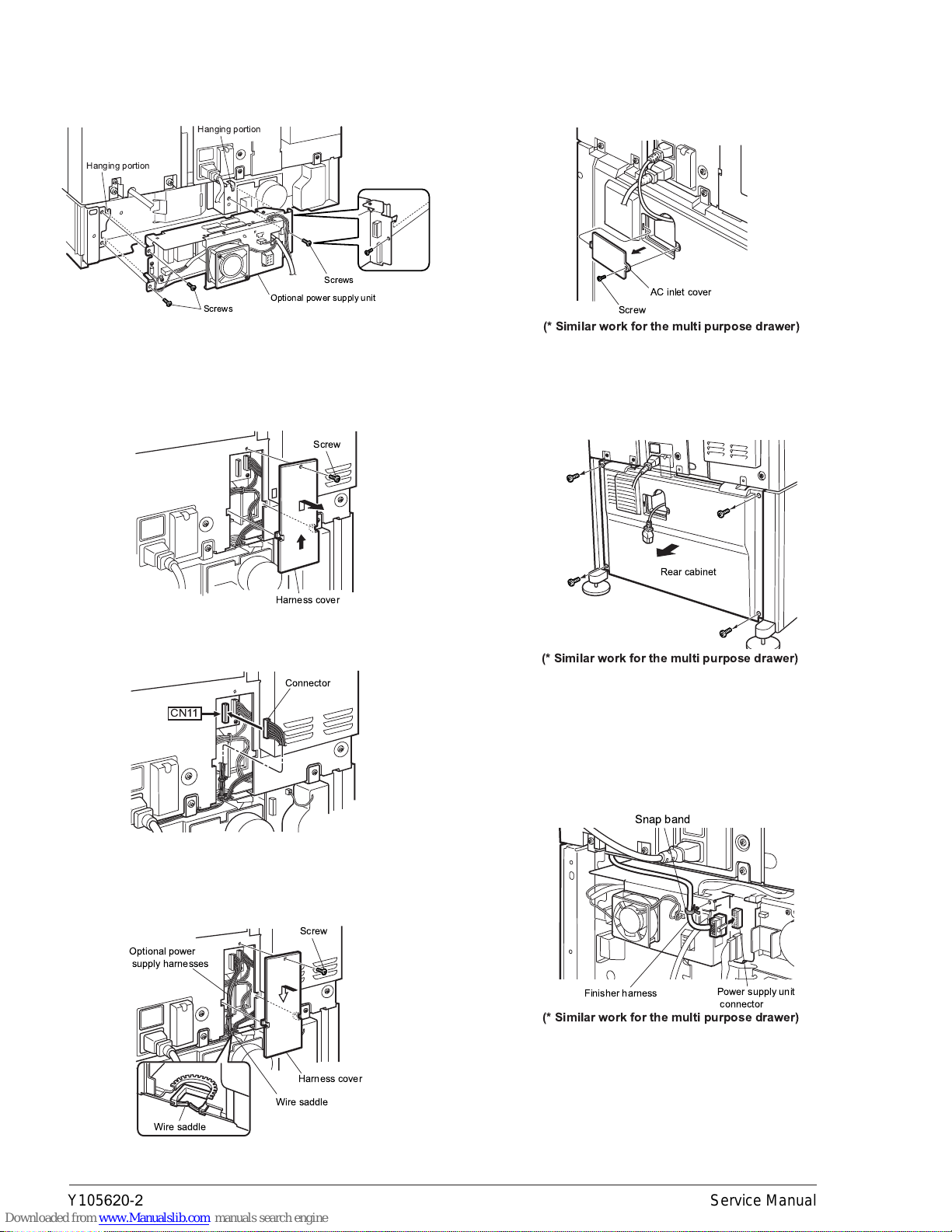
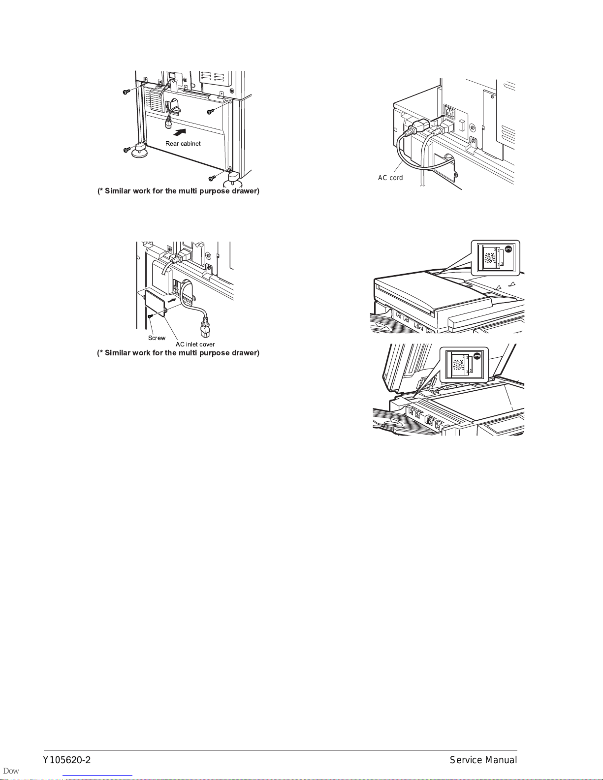
Power source Supplied from the optional power source
(AR-DC1)
(DC24V 2.7A / DC5V 0.5A)
External
dimensions(WxDxH) 460 x 530 x 508 (mm)
Occupied
dimensions(WxD) 460 x 530 (mm)
Weight Approx. 21kg
Offset stack Offset volume:25mm
Paper size to be
stapled A4, B5, 8.5"x11"
Ability of stapler
(Max. # of pages
for staple)
30 sheets (smaller than A4/8.5"x11", 80g/m²)
Stapling pattern 3 patterns (front 1/rear 1/both)
Stacking
performance Offset Horizontal displacement:
Less than 15mm
(Less than 10mm up to
250 sheets)
Vertical displacement:
Less than 15mm
(In the non-staple mode on
the offset tray)
Matching Max. deviation width Within 2mm
(In the staple mode on the
offset tray)
Staple supply Refill system
Staple detection Staple empty Provided
No cartridge Provided
Staple jam Provided
Kinds of paper
which cannot be
stapled
Pre-punched paper, transparency film, heavy paper,
label, envelope, postcard
Name Content Life Product
name Remark
Staple
cartridge Staple
cartridge x3 3000x3 AR-SC1 Common with cartridge
for AR-FN4 & AR-FN6
!"#$
Y105620-2Service Manual

4-1
[4] UNPACKING AND INSTALLATION
<Before installation>
•Start installation after checking that the DATA and COMMUNICATION
indicators on the operation panel are neither lit nor blinking.
•For installation of AR-FN6, an optional stand/paper drawer (stand/MPD
& 2000 sheet paper drawer, stand/3 x 500 sheet paper drawer or multi
purpose drawer) must have been installed.
Also if a multi purpose drawer has been installed, a power supply unit
(AR-DC1) is needed additionally.
1) Turn off the main switch of the main unit of the printer.
Turn the main switch located on the front side of the main unit to the
"OFF" position.
Then, remove the power plug of the main unit from the outlet.
2) Remove the upper cabinet of the stand/paper drawer.
<1>Pull out the paper tray of the stand/paper drawer.
Remove the four screws attached to the right on the top of the stand/
paper drawer and remove the cabinet.
<2>Mount screw B to the position shown in the illustration.
3) Attach the finisher.
<1>Remove the paper exit actuator from the main unit of the printer.
<2>Raise the relay unit at the side of the finisher.
<3>Hold the grip of the finisher and place the finisher on the stand/paper
drawer temporarily.
Then, push the lower part to attach the finisher by sliding it toward
the exit tray of the main unit.
At this time, align the finisher with the exterior line of the stand/paper
drawer.
<Parts included>
Mounting plates: 2 pcs. Staple cartridge: 1 pc.
Tray 1: 1 pc.
Screws A (M4x8): 5 pcs.
Screw B: 1 pc.
Tray 2: 1 pc.
Stapling position labels:
2 sheets
"OFF"
Cabinet
Screw B
Actuator
Relay unit
Push.
Push.
Place.
Grip
Grip
"# $%&'(
Y105620-2Service Manual

4-2
<4>Open the front cover of the finisher and fix the finisher with three
screws A at the positions shown in the illustration.
Then, close the front cover and close the paper tray of the stand/
paper drawer.
<5>Attach the mounting plates to the positions shown in the illustration
and fix them with screws A.
Caution: Insert the mounting plate under the desk frame.
4) Insert the staple cartridge.
<1>Pull out the staple unit.
<2>Remove the sealing tape from the staple cartridge.
<3>Insert the staple cartridge.
<4>Slide the release lever to the left and return the staple unit.
5) Attach the trays.
Attach tray 1, tray 2 to the positions shown in the illustration.
Steps 6) and after are the procedure to be carried out when a multi
purpose drawer has been installed.
If a stand/MPD & 2000 sheet paper drawer or a stand/3 x 500 sheet
paper drawer has been installed, carry out steps 9).
6) Process the AC inlet cover attached to the rear cabinet of the stand/
paper drawer.
<1>Remove the two screws that secure the rear cabinet and remove the
rear cabinet.
<2>Remove the screw that fixes the AC inlet cover and then remove the
AC inlet cover.
Process the AC inlet cover as shown in the illustration.
Screws A
Screws A
(Front side)
Mounting plates
Screws A
(Rear side)
Desk frame
Mounting plate
Tray 1
Tray 2
Screw
Screw
Screw
Rear
cabinet
AC inlet cover
Cut out.
AC inlet cover
) "# $%&'(
Y105620-2Service Manual

4-3
7) Attach the power supply unit.
Attach the power supply unit to the hanging portions and secure it
using the supplied three screws.
8) Connect the power supply unit harness to the PCU PWB of the main
unit of the printer.
<1>Remove the screw that fixes the harness cover of the main unit of the
printer and slide the harness cover up to remove it.
Process the harness cover as shown in the illustration.
<2>Connect the power supply unit harness connector to CN11
(red connector) of the PCU PWB of the main unit of the printer.
<3>Reattach the harness cover to its original position and fix it with the
removed screw.
At this time, ensure that the power supply unit harness is arranged
as shown in the illustration.
* Fix the harness securely to the wire saddle.
9) Remove the AC inlet cover and then remove the rear cabinet of the
stand/paper drawer.
<1>Remove the screw that fixes the AC inlet cover and then remove the
AC inlet cover.
<2>Remove the AC cord of the power supply unit from the inlet
connector of the main unit of the printer.
Remove the four screws that fixthe rear cabinet and then remove the
rear cabinet.
10) Arrange the harness of the finisher.
<1>Pass the harness of the finisher between the power supply unit and
the frame of the stand/paper drawer and connect it to the connector
of the power supply unit.
<2>Fit the snap band attached to the finisher at the position shown in the
illustration to fix the harness.
Optional power supply unit
Screws
Screws
Hanging portion
Hanging portion
Harness cover
Screw
Connector
CN11
Wire saddle
Harness cover
Optional power
supply harnesses
Screw
Wire saddle
Wire saddle
Screw
AC inlet cover
(* Similar work for the multi purpose drawer)
Rear cabinet
(* Similar work for the multi purpose drawer)
Snap band
Finisher harness Power supply unit
connector
(* Similar work for the multi purpose drawer)
* "# $%&'(
Y105620-2Service Manual

4-4
11) Attach the rear cabinet of the stand/paper drawer.
<1>Pass the AC cord of the power supply unit as shown in the illustration
and fix the rear cabinet of the stand/paper drawer with the screws.
<2>Attach the AC inlet cover to the rear cabinet of the stand/paper
drawer and fix it with the removed screw.
12) Connect the AC cord of the optional power supply unit to the main
unit of the printer.
<1>Connect the AC cord of the power supply unit to the inlet connector
of the main unit of the printer at the location shown in the illustration.
13) Paste the stapling position label.
(Paste it only if the scanner module is installed.)
Paste the label to the position shown in the illustration.
Rear cabinet
(* Similar work for the multi purpose drawer)
Screw AC inlet cover
(* Similar work for the multi purpose drawer)
AC cord
"# $%&'&(
Y105620-2Service Manual

5-1
[5] EXTERNAL VIEWS AND INTERNAL STRUCTURES
A. External view
B. Internal structure
1 Top cover 2 SF Knob 3 Top tray 4 Staple cartridge
5 Offset tray 6 Front door 7 Staple unit
1 Finisher transport roller R1 2 De-curler roller 3 Transport roller R2
4 No.1 tray paper exit roller 5 S paper entry roller 6 Transport roller R2
7 Stapler unit 8 Lower tray paper exit roller 9 Alignment tray
23
5
6
4
17
123
5
4
98
6
7
! "#$%&
Y105620-2Service Manual

5-2
C.Sensor
Code Name Function Active condition Remark
1 PID Paper In Detect Sensor Detection of paper entry into the
interface transport section L : Paper loaded
2 DOPD Door Open Detect Sensor Upper side cover open/close detection L : Door open
3 T1PF Tray 1 Paper Full Detect Sensor Upper side tray paper exit full detection L : Paper full
4 PPD Paper pushl Detect Sensor Detection of paper holding return in the
compiler H : Home position
5 SCID Staple Compiler In Detect Sensor 2 Staple paper entry detection L : Paper loaded
6 SCID2 Staple Compiler In Detect Sensor Staple paper entry detection L : Paper loaded
7 SCPD Staple Compiler Paper Detect Sensor Paper detection in the compiler L : Paper loaded
8 JFHP Jogger Front Home Position Sensor Jogger F home position detection H : Home position
9 JRHP Jogger Rear Home Position Sensor Jogger R home position detection H : Home position
10 PSHP Pushher Home Position Sensor Pusher home position detection H : Home position
11 STTHP1 Staple Turn Home Position Sensor 1 Staple rotation home position detection Detected by combination
of STTHP1 and STTHP2
12 STTHP2 Staple Turn Home Position Sensor 2 Staple rotation home position detection
13 STUHP Staple Turn Home Position Sensor Staple shift home position detection H : Home position
14 POD Paper Out Detect Sensor Paper exit detection L : Paper loaded
15 T2UP Tray 2 Upper Detect Sensor Offset tray upper limit position
detection H : Upper limit
16 T2DN Tray 2 Down Detect Sensor Offset tray lower limit position detection H : Lower limit
17 T2PD Tray 2 Paper Detect Sensor Offset tray paper empty detection L : Paper loaded
18 DSW1 Door Switch 1 Right upper door open/close detection L : Door open
19 DSW2 Door Switch 2 Front door open/close detection L : Door open
20 STHP Stapler Home Position Sensor Stapler home position detection L : Home position
21 STNC Stapler No Cartridge Sensor Stapler cartridge empty detection H : Empty
22 STLS Stapler Low Staple Sensor Stapler staple empty detection H : Empty
23 STSP Stapler Self Priming Sensor Stapler staple ready position detection L : Ready
1.PID
2.DOPD
3.T1PF
9.JRHP
18.DSW1
7.SCPD
15.T2UP
14.POD
16.T2DN
23.STSP
22.STLS
21.STNC
20.STHP
19.DSW2
11.STTHP1
12.STTHP2
4.PPD
8.JFHP
13.STUHP
5.SCID
6.SCID2
10.PSHP
17.T2PD
' ! "#$%&
Y105620-2Service Manual

5-3
D. Motor, Clutch, Solenoid, PWB
Code Name Function Remark
1 Main PWB Main Control PWB Communication with the machine, control of the machine operations
2 MM Main Motor Drives transport rollers
3 JFM Jogger Front Motor F side alignment plate drive
4 JRM Jogger Rear Motor R side alignment plate drive
5 PSM Pushher Motor Pusher drive
6 STM Staple Motor Staple drive
7 STUM Staple Unit Motor Stapler shift
8 STTM Staple Unit Turn Motor Stapler rotation
9 EVM Elevator Motor Offset tray up-down shift
10 T2OM Tray 2 Ouput Motor Drive of paper exit paddler to offset tray
11 FGS Finisher Gate Solenoid Paper entry gate selection
12 SCGS Staple Compiler Gate Solenoid Staple paper entry gate selection
13 SCRS Staple Compiler Rolor Solenoid Belt roller press/release selection
14 PPS Paper Push Solenoid Paper rear edge holding drive selection
15 SPS Stopper Solenoid Stopper drive selection
16 T2S Tray 2 Solenoid Paper exit paddler drive selection
1.Main PWB
2.MM
3.JFM
4.JRM
5.PSM
6.STM
7.STUM
8.STTM
9.EVM
10.T2OM
11.FGS
12.SCGS
13.SCRS
14.PPS
15.SPS
16.T2S
( ! "#$%&
Y105620-2Service Manual

6-1
[6] MACHINE OPERATION
1. Using the stapling function from the printer feature
When using the stapling function, select "Properties" on the printer driver setting screen, open the "Main" tab shown in the right illustration, and then
select "Left", "Right" or "Top " at "Binding Edge" and "1 Staple" or "2 Staples" in the "Staple" drop down.
NOTES:
•The settings screens above will appear only if the devices have been set properly in the printer driver.
•The combination of paper selection and other functions may not be compatible. For instance, if heavy paper, envelopes, label stock, etc. are selected,
it will not be possible to select duplex, offset tray, saddle stitch, etc.
The illustration below shows the screen for a PCL printer driver in the Windows 98 environment.
2. Using the finisher functions in the copy mode
If you touch the [OUTPUT] key on the copy mode basic screen, a screen for selecting the sort/group/staple sort functions and selecting an exit tray will
appear.
1 : [GROUP] key
If this function is selected, all copies of the same original will be grouped.
2 : [STAPLE SORT] key
If this function is selected, sorted copies will be stapled and delivered to
the offset tray. (not offset stacked)
3 : [SORT] key
If this function is selected, each set of copies will be sequentially
delivered.
4 : Icon display
The icon of the selected function (sort, staple sort or group) is displayed.
5 : [OFFSET] key
If this function is selected (checked), the offset function will be enabled. If
the check mark is cleared, the offset function will be disabled. (If the
staple sort function is selected, the check mark of the offset function will
be automatically cleared.)
6 : [OFFSET TRAY] key
If the offset tray is selected, printed sheets will be delivered to the offset
tray. (If the staple sort function is selected, the offset tray will be
automatically selected.)
7 : [TOP TRAY] key
If the top tray is selected, printed sheets will be delivered to the top tray.
8 : [OK] key
Press to close this screen and to return to the basic screen.
* If a function is selected, the corresponding key will be highlighted.
OK
STAPLE
SORT
OUTPUT
GROUP
SORT
OFFSET
TRAY
TOP TRAY
OFFSET
123 45
6
7
8
! "#$%&
Y105620-2Service Manual

6-2
3. Stapling position quick reference list
When stapling is performed, the orientation of image data or original is related to the stapling position, binding position and orientation of paper
complicatedly. The table below shows the relation.
NOTES:
•When using the stapling function, select the offset tray as an exit tray. If another tray is selected, the stapling function cannot be used.
•Select only one paper size. If different sizes are included, stapling cannot be performed.
* The following types of paper cannot be stapled.
Pre-punched paper, transparency film, heavy paper, label, envelope, postcard
Image data or original Result
First page (front side)
Second page (reverse side)
Two sides
Portrait orientation printing
Left binding Top binding Right binding Left binding Top binding Right binding
One-position stapling Two-position stapling
One-position stapling
Landscape orientation printing
Two-position staplingOne-position stapling
One-position stapling
One-position stapling Two-position
stapling with left
binding cannot be
made.
Two-position
stapling with right
binding cannot be
made.
Two-position
stapling with top
binding cannot be
made.
indicates stapling positions.
' ! "#$%&
Y105620-2Service Manual

7-1
[7] OPERATIONAL DESCRIPTIONS
1. Paper transport path
A. Machine paper exit reverse (Switchback)
When the duplex print or the left side paper exit tray is selected, paper is
once discharged to the interface unit and then switched back.
B. Paper exit to the upper tray
In the normal paper exit operation, paper is discharged to the upper tray.
C. Paper exit to the lower tray
When stapling or offset operation is performed, paper is discharged to
the lower tray.
2. Descriptions of each section
The finisher is composed of (1) upper paper transport section, (2)
alignment tray section, and (3) tray 2 paper exit section.
Offset and stapling (3 positions) can be performed with paper exit to tray
2 as well as the selected tray by the command from the machine.
12
12
1
23
(1) Upper paper transport section
(2) Alignment tray section
Stapler
(3) Tray 2 paper exit section
!" #$%&'

7-2
A. Upper transport section
(1) Paper transport path
By rotating the main motor (MM), all the transport rollers in the unit
(except for the tray 2 final roller) are driven.
(2) Interface unit paper entry gate
The finisher gate solenoid (FGS) operates the interface unit paper entry
gate to perform machine paper exit reversion and selection of the paper
path to the tray 1 and the tray 2.
(3) S paper entry gate
The compiler paper entry gate solenoid (SCGS) operates the S paper
entry gate to select the paper path to the tray 1 or the tray 2.
(4) Tray 1 paper full detection
Tray 1 paper full detection is performed by the tray 1paper full sensor
(T1PF) in linkage with the tray 1 paper full actuator.
B. Alignment tray section
(1) Jogger F/R
The jogger F/R motors (JFM, JRM) are driven at the timing of paper
entry into the alignment tray to operate the joggers F/R (alignment plates
on both sides), making transverse alignment of paper.
(2) Pusher
The pusher motor (PSM) is driven at the timing of paper entry into the
alignment tray to operate the pusher (upper alignment plate). Paper is
squeezed with the pusher and the stopper which is provided at the lead
edge of paper to make longitudinal alignment of paper. The pusher also
serves to hold the rear edge of a paper bundle in order not to change the
sequence of the next paper when it enters the alignment tray. It also
pushes a stapled paper bundle to the tray 2 in the staple mode.
(3) Stopper
The stopper is driven by the stopper solenoid (SPS) to stop the lead
edge of paper in order to hold paper in the alignment tray.
(4) Pressure release roller
The pressure release roller is driven by the pressure release solenoid
(SCRS). It is pressed when paper is transported from the alignment tray
to the tray 2. It also serves to improve longitudinal alignment capability
when paper enters the alignment tray in the staple mode.
(5) Paper holder
The paper holder is driven by the paper holder solenoid (PPS) to hold the
rear edge of paper in the alignment tray.
(6) Alignment and paper exit in offset
1) The joggers F/R are moved to the standby position before paper
entry into the alignment tray, and paper is passed to the alignment
tray.
2) When paper is passed into the alignment tray, the stopper solenoid is
turned on to receive paper.
3) After paper entry into the alignment tray, the joggers are moved to
the suitable positions according to the paper size, and paper is
offset.
4) The stopper solenoid is turned off and the pressure release (roller)
solenoid is turned on to discharge paper to the tray 2.
(7) Alignment in stapling
1) Before paper entry into the alignment tray, the joggers F/R are
moved to the standby position, and paper is entered into the
alignment tray.
2) When paper enters the alignment tray, the stopper solenoid is turned
on to receive paper.
3) After paper entry into the alignment tray, the joggers F/F are moved
to the paper size positions to align paper.
4) The paper holder solenoid is turned on at the same time with (3) to
hold the rear edge of entered paper, and the pusher is moved to the
paper size position.
5) After completion of moving the pusher, the paper holder solenoid is
turned off.
Paper entry sensor (PID)
S paper entry gate
Tray 1
paper full actuator
Staple paper entry sensor 2
(SCID2)
Interface unit paper entry gate
Staple paper entry sensor 1 (SCID)
Tray 1 paper full sensor (T1SP)
Paper size
Stopper
Center reference
Paper exit
Jogger RJogger F
1
2
4
3
Pressure release roller
Paper size
Stopper
Center reference
Pusher
Jogger RJogger F
1
1
2
4
3
5
3
Paper holder
( !" #$%&'
Y105620-2Service Manual

7-3
(8) Staple unit
The stapler staples paper. The ST shift motor slides the stapler
horizontally with the paper lead edge according to the staple positions
(forward, backward, 2 positions).
The ST rotating motor (STTM) rotates the stapler from the save position
to the stapling position, and can slide the staple replacement position
horizontally and can discharge paper.
(9) Stapler
The stapler can staple max. 30 pages of 80g paper. It is composed of the
drive DC motor (STM), the home position sensor (STHP), the staple
empty sensor (STLS), the cartridge empty sensor (STNC), and the self-
priming sensor (STSP) which detects a staplable position.
(10) Stapling
1) The stapler is moved from the staple replacement position to the
slidable position.
2) The stapler is shifted to the stapling position.
3) The stapler is rotated to the stapling position.
Put paper to be stapled in the staple tray.
4) Paper is stapled.
5) The stapler is rotated to the standby position.
When in one-position stapling, a bundle of paper is discharged to the
tray 2 (paper exit section), and the procedure goes to (10)
6) The stapler is shifted to the second stapling position.
7) The stapler is rotated to the stapling position.
8) Paper is stapled. (Second stapling)
9) The stapler is rotated to the standby position.
The bundle of paper is discharged to the tray 2 (paper exit section)
10) After completion of a job, the stapler is shifted to the staple
replacement position.
11) The stapler is rotated to the staple replacement position.
For one-position stapling, however, procedures (6) - (10) are not
performed.
(11) Paper exit after stapling
1) The joggers F/R are moved to the paper exit position.
2) The stopper solenoid is turned off.
3) The pressure release solenoid is turned on to shift the pusher to the
paper exit position, and the paper bundle is discharged to the tray 2
paper exit section.
4) The pressure release solenoid is turned off and the pusher is
returned to the home position.
C. Tray 2 paper exit section
(1) Paper transport
Only in paper exit to the tray 2, the final roller is driven by rotating the
paper exit motor (T2OM).
(2) Elevator operation and tray 2 paper full detection
The elevator motor is rotated to move the tray 2 up and down so that
paper is discharged at the fixed position according to the quantity of
paper loaded in the tray 2.
The tray 2 full is detected when both the tray 2 upper limit sensor which is
linked with the tray 2 upper limit actuator and the tray 2 lower limit sensor
are on.
2 6
7
11 10
3
1
4
5
8
9
Staple
replacement
position
Pusher
Jogger R
Jogger F
1 1
4
3
3
Stopper
2
Pressure release roller
Paper bundle exit
) !" #$%&'
Y105620-2Service Manual

7-4
(3) Paddler operation/tray 2 upper limit detection actuator operation
When the paper exit motor is rotating, the tray 2 solenoid (T2S) is turned on so that the paddler is rotated to pull paper and pull the actuator toward the
unit in order to improve the stacking capacity of paper loaded in the tray 2.
3. Basic operation
A. Basic operation flow
Paper exit sensor
(POD)
Paddler
Tray 2 upper limit
detection actuator
Tray 2 upper limit sensor
(T2UP)
Tray 2 lower limit sensor
(T2DN)
Power on
Standby
Transport operation
Alignment operation
Stapling operation
Paper exit operation
Operation
in case of a jam
Standby
for jam cancel
Initializing
(After completion
of a job)
Paper exit end
Jam occurrence
Machine paper feed start
Initializing
Door close
Door open
Door open
Door open
Door open state
* !" #$%&'
Y105620-2Service Manual

8-1
[8] ADJUSTMENTS
1. Jogger position adjustment
A. Jogger F/R
1) Staple 5 sheets of A4 or LT paper and check the paper shift (A)
shown in the figure below.
2) If the shift (A) is less than 1mm, there is no need to adjust.
3) If the shift (A) is 1mm or greater, adjust as shown in the table below.
B. Printer model adjustment procedure
1) In the DIAG MODE, select [FINISHER JOGGER ADJ.].
2) Press [OK] key, and the following display will be shown.
Use [ ] key and [ ] key to change the adjustments value.
(Adjustment range: 40 - 60)
3) Change the adjustment value and press OK key, and the stopper will
be turned on and the finisher joggers F/R will move to and stop at the
positions shown in the table below.
4) When the joggers F/R stop, open the door and load A$/LT paper in
the alignment tray, and check the jogger width visually.
5) When the jogger width is too wide or too narrow, use [ ] key and
[ ] key again to change the adjustments value. Press [OK] key to
shift the jogger to the A4/LT alignment position, and check visually.
The table below shows relationship between the adjustment value and
the jogger width.
6) After completion of the adjustment, remove the paper from the
alignment tray and terminate the DIAG MODE.
C. MFP adjustment procedure
1) When the sub code of the simulation is entered, the following display
is shown.
SIM 3-6: Jogger position adjustment
2) Enter the adjustment value with [0] - [9] keys and press START key,
and the menu below will be displayed. (Adjustment range: 40 - 60)
SIM 3-6: Jogger moving
When the stopper is turned on, and finisher joggers F/R move to and
stop at the positions shown in the table below.
3) When the joggers F/R stop, open the door and load A4/LT paper in
the alignment tray, and check the jogger width visually.
4) When the jogger width is too wide or too narrow, use [0] - [9] key
again to change the adjustments value. Press [START] key to shift
the jogger to the A4/LT alignment position, and check visually.
The table below shows relationship between the adjustment value and
the jogger width.
5) After completion of the adjustment, remove the paper from the
alignment tray and terminate the simulation.
Model Adjustment procedure
Pinter model DIAG MODE
[FINISHER JOGGER ADJ.]
(Finisher jogger position adjustment)
MFP SIM 3-6(Built-in finisher jogger position adjustment)
Destination Jogger position
Inch series LT size alignment position
AB series A4 size alignment position
(A)
Staple
Jogger F Jogger R
FINISHER JOGGER ADJ.
ADJUST VALUE 50
Adjustment value Jogger width
Decreased by 1. Increased by about 0.375mm.
Increased by 1. Decreased by about 0.375mm
Destination Jogger position
Inch series LT size alignment position
AB series A4 size alignment position
Adjustment value Jogger width
Decreased by 1. Increased by about 0.375mm.
Increased by 1. Decreased by about 0.375mm
SIMULATION 3-6
FINISHER JOGGER ADJUSTMENT.INPUT VALUE 40-60,AND PRESS START.
50
SIMULATION 3-6
FINISHER JOGGER ADJUSTMENT.MOVING...
50
!"#$
Y105620-2Service Manual

9-1
[9]DISASSEMBLYAND ASSEMBLY,MAINTENANCE
1. Maintenance System Table
Check (Clean, replace, or adjust as necessary.) Clean Replace Adjust Lubricate Move position
Unit name Part name When
calling 50K 100K 150K 200K 250K 300K 350K 400K Remark
Transport section Transport rollers
De-curler roller ( )
Transport paper
guides
Drive section Gears (Specified position)
Belts
Other Sensors
Discharge brush
Staple un Replace UN at 100K staple.
Staple cartridge User replacement for every 3000pcs.
! "#$%&
Y105620-2Service Manual
Table of contents
Other Olivetti Printer Accessories manuals