E-2
Note:
This manual provides the illustrations of the acces-
sory parts and machine that may be slightly differ-
ent in shape from yours. In that case, instead of
the illustrations, use the appearance of your
machine to follow the installation procedure. This
does not cause any significant change or problem
with the procedure.
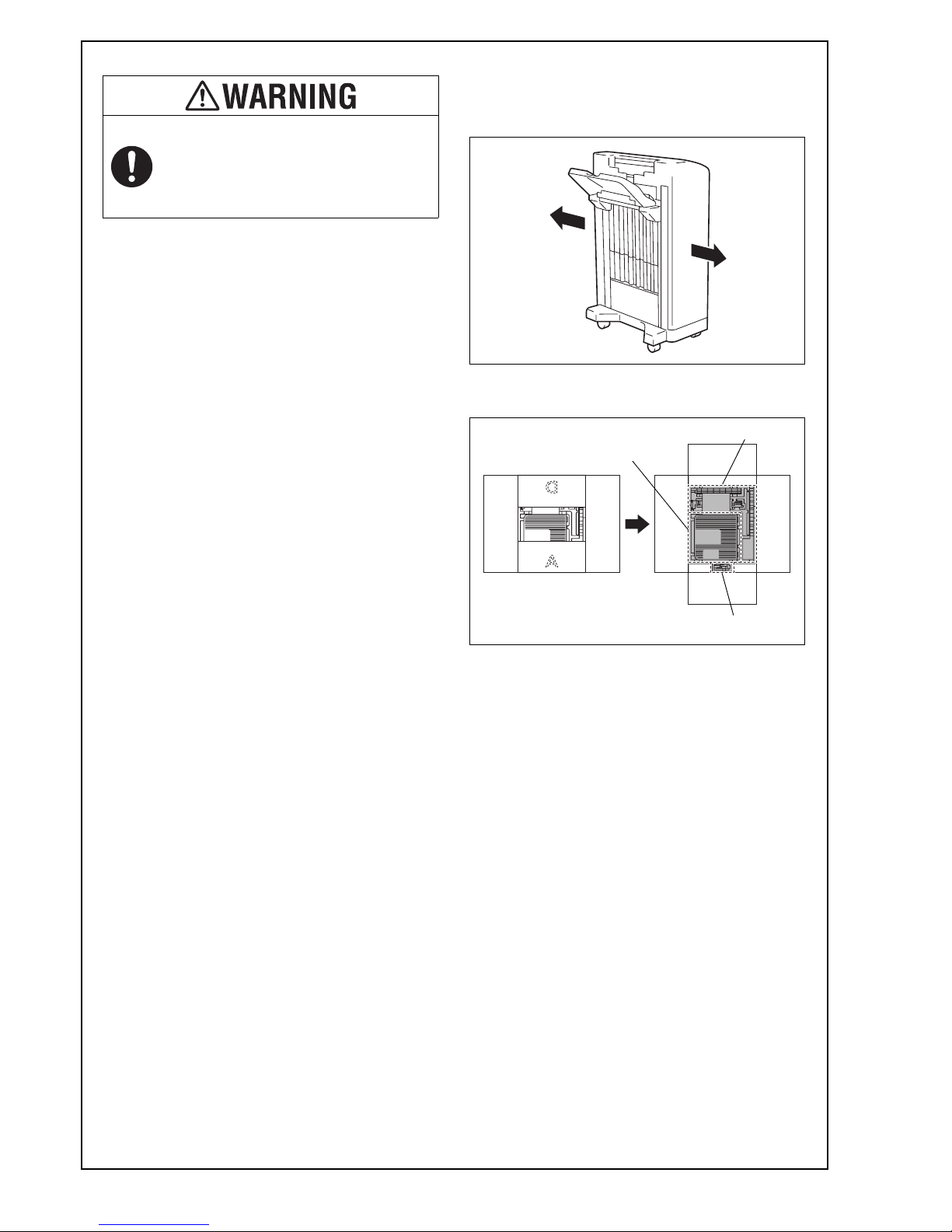
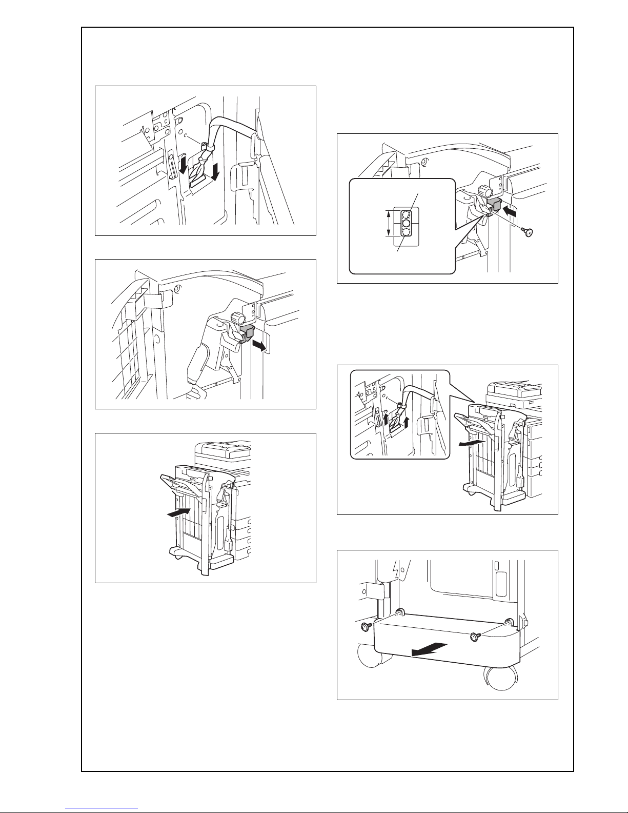
II. Confirmation before installation
1. To move the finisher, be sure to push it in the
directions of the arrows as shown in the illustra-
tion. (Precaution against falling of the finisher).
2. Parts are arranged in a box as shown in the illus-
tration.
3. Choose a horizontal and stable floor for installing
the machine.
4. The packaging material should not be reused for
repacking.
5. When installing the optional punch kit, saddle
stitcher, and separator (JS-603), install the punch
kit, saddle stitcher, and separator (JS-603) first
and then install the finisher.
After unpacking, be sure to get rid of the
packaging materials and keep them out of
the reach of children.
Putting the head in the plastic bag
involves danger of suffocation.
A0HRIXC012DA
A0HRIXC046DB
Partsfor MF360/MF280/MF220
Common parts
Parts for MF451
Installation Manual Y111090-1


 User manual")


