manuals.online logo
Brands
  1. Home
  2. •
  3. Brands
  4. •
  5. OLT
  6. •
  7. Garden House
  8. •
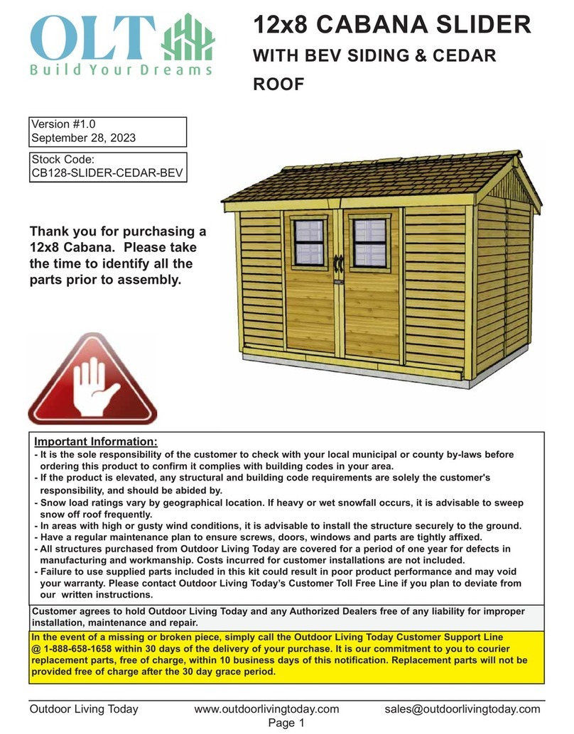
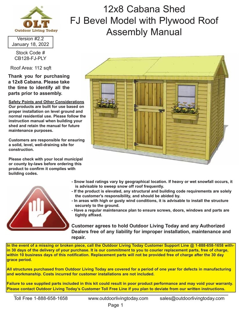
  9. OLT 12x8 Cabana User manual

OLT 12x8 Cabana User manual

Other manuals for 12x8 Cabana

1

Other OLT Garden House manuals

OLT GS84-SLIDER-METAL-AK User manual

OLT

OLT GS84-SLIDER-METAL-AK User manual

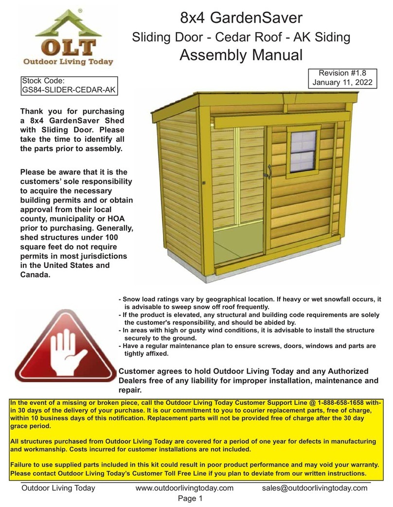
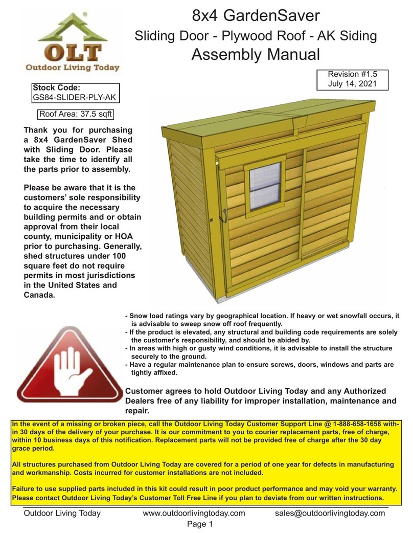
OLT 8x4 GardenSaver User manual

OLT

OLT 8x4 GardenSaver User manual

OLT GS63-TG-METAL User manual

OLT

OLT GS63-TG-METAL User manual

OLT GS124-SLIDER-CEDAR-AK User manual

OLT

OLT GS124-SLIDER-CEDAR-AK User manual

OLT SpaceSaver SS124-SLIDER-METAL-AK User manual

OLT

OLT SpaceSaver SS124-SLIDER-METAL-AK User manual

OLT SunShed Greenhouse 8x12 User manual
OLT

OLT SunShed Greenhouse 8x12 User manual

OLT GS84-D-FJ User manual

OLT

OLT GS84-D-FJ User manual

OLT Garden Chalet 4x2 User manual

OLT

OLT Garden Chalet 4x2 User manual

OLT SpaceSaver SS124-SLIDER-CEDAR-AK User manual

OLT

OLT SpaceSaver SS124-SLIDER-CEDAR-AK User manual

OLT 9x6 Cabana User manual

OLT

OLT 9x6 Cabana User manual

OLT GS84-SLIDER-PLY-FJ User manual

OLT

OLT GS84-SLIDER-PLY-FJ User manual

OLT FJ Bevel User manual

OLT

OLT FJ Bevel User manual

OLT Studio Garden Shed STU128-FJ-Metal User manual

OLT

OLT Studio Garden Shed STU128-FJ-Metal User manual

OLT 8x8 Pine SpaceMaker User manual

OLT

OLT 8x8 Pine SpaceMaker User manual

OLT STU128-Metal User manual

OLT

OLT STU128-Metal User manual

OLT SpaceSaver SS124-SLIDER-PLY-FJ User manual

OLT

OLT SpaceSaver SS124-SLIDER-PLY-FJ User manual

OLT 8x4 GardenSaver User manual

OLT

OLT 8x4 GardenSaver User manual

OLT 8x4 SpaceSaver Garden Shed Bevel Model with Plywood... User manual

OLT

OLT 8x4 SpaceSaver Garden Shed Bevel Model with Plywood... User manual

OLT CB128-SLIDER-METAL-BEV User manual

OLT

OLT CB128-SLIDER-METAL-BEV User manual

OLT 12x16 Sunshed Garden User manual

OLT

OLT 12x16 Sunshed Garden User manual

OLT SS84-SLIDER-Ply-AK User manual

OLT

OLT SS84-SLIDER-Ply-AK User manual

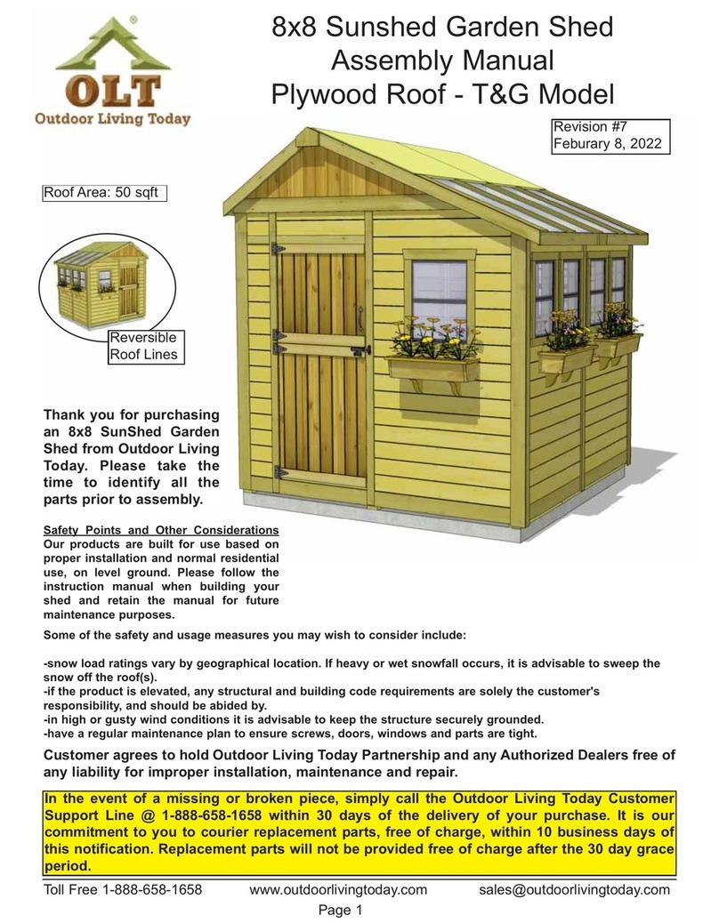
OLT 12x8 Cabana Garden Shed User manual

OLT

OLT 12x8 Cabana Garden Shed User manual

OLT 6x6 Apex User manual

OLT

OLT 6x6 Apex User manual

OLT SunShed SSGS1216-FJ-Cedar User manual

OLT

OLT SunShed SSGS1216-FJ-Cedar User manual

Popular Garden House manuals by other brands
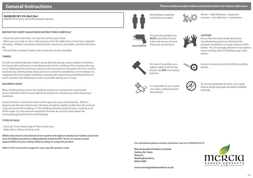
Yardmaster 66 ZGEY Assembly instructions

Yardmaster

Yardmaster 66 ZGEY Assembly instructions

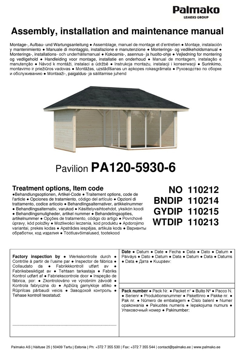
Mercia Garden Products 0628LOG181-V4 manual
Mercia Garden Products

Mercia Garden Products 0628LOG181-V4 manual

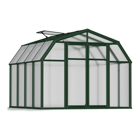
Lemeks Palmako PA120-5930-6 Assembly, installation and maintenance manual
Lemeks

Lemeks Palmako PA120-5930-6 Assembly, installation and maintenance manual

Rion Hobby Gardener Assembly instructions

Rion

Rion Hobby Gardener Assembly instructions

Select ISAAC E9682 Assembly manual

Select

Select ISAAC E9682 Assembly manual

Palmako Saale installation manual

Palmako

Palmako Saale installation manual

Palmako Roger FR44-5953-2 installation manual

Palmako

Palmako Roger FR44-5953-2 installation manual

Lemeks Palmako Grace PM56-4529 Assembly, installation and maintenance manual

Lemeks

Lemeks Palmako Grace PM56-4529 Assembly, installation and maintenance manual

Mercia Garden Products 03WES0808-V1 General instructions

Mercia Garden Products

Mercia Garden Products 03WES0808-V1 General instructions

Mercia Garden Products 03DTSHHP1206HGD4MW-V1 General instructions

Mercia Garden Products

Mercia Garden Products 03DTSHHP1206HGD4MW-V1 General instructions

Shire Salcey Assembly

Shire

Shire Salcey Assembly

Pergola kits USA PREMIUM VINYL PAVILION Assembly manual

Pergola kits USA

Pergola kits USA PREMIUM VINYL PAVILION Assembly manual

G21 Boston 882 manual

G21

G21 Boston 882 manual

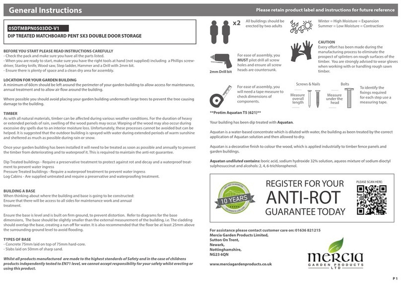
Mercia Garden Products 05DTMBPN0503DD-V1 Assembly instructions

Mercia Garden Products

Mercia Garden Products 05DTMBPN0503DD-V1 Assembly instructions

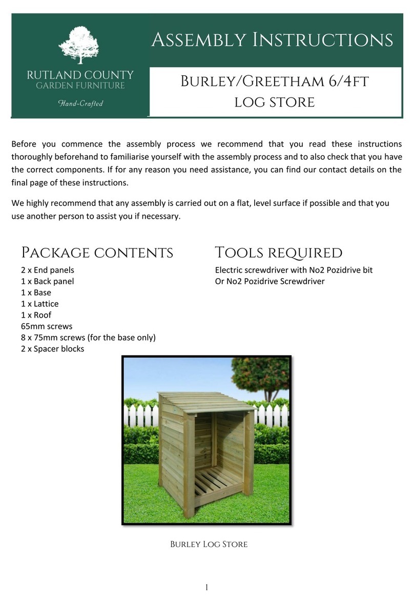
Rutland County Burley 6ft Assembly instructions

Rutland County

Rutland County Burley 6ft Assembly instructions

Palmako Roger 27,7 installation manual

Palmako

Palmako Roger 27,7 installation manual

Mercia Garden Products 01PTOSBA0306DDNW-V1 General instructions

Mercia Garden Products

Mercia Garden Products 01PTOSBA0306DDNW-V1 General instructions

Gartenhaus-King Valery manual

Gartenhaus-King

Gartenhaus-King Valery manual

manuals.online logo
manuals.online logoBrands
  • About & Mission
  • Contact us
  • Privacy Policy
  • Terms and Conditions

Copyright 2025 Manuals.Online. All Rights Reserved.

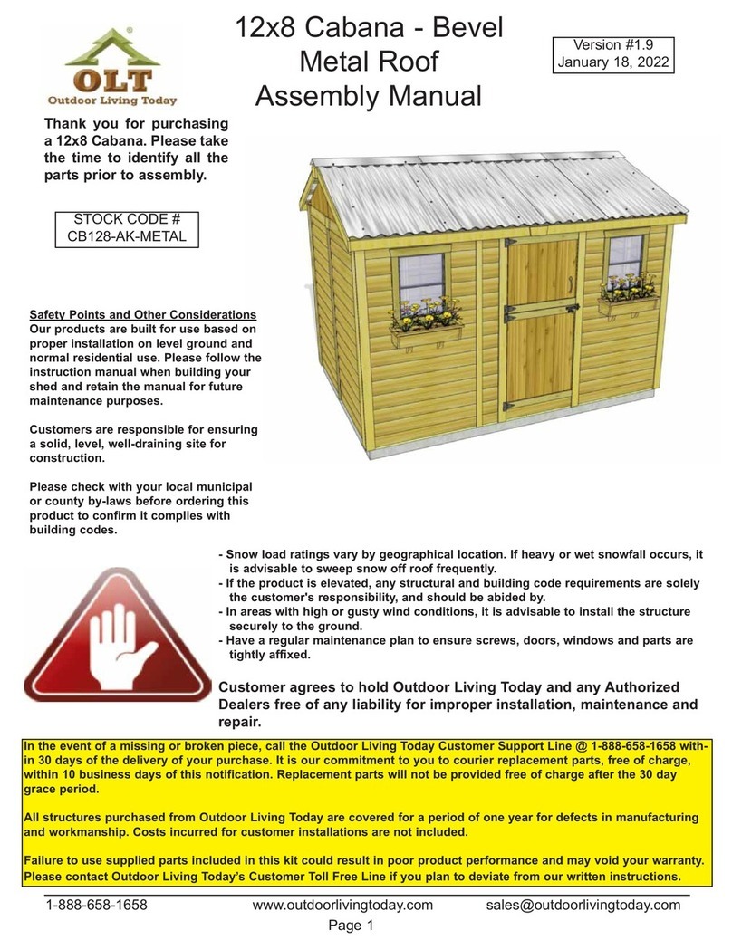
12x8 Cabana - Plywood
Assembly Manual
Version #2.0
August 18, 2020
1-888-658-1658 www.outdoorlivingtoday.com sales@outdoorlivingtoday.com
Page 1
Thank you for purchasing
a 12x8 Cabana. Please take
the time to identify all the
parts prior to assembly.
In the event of a missing or broken piece, call the Outdoor Living Today Customer Support Line @ 1-888-658-1658 with-
in 30 days of the delivery of your purchase. It is our commitment to you to courier replacement parts, free of charge,
within 10 business days of this notification. Replacement parts will not be provided free of charge after the 30 day
grace period.
All structures purchased from Outdoor Living Today are covered for a period of one year for defects in manufacturing
and workmanship. Costs incurred for customer installations are not included.
Failure to use supplied parts included in this kit could result in poor product performance and may void your warranty.
Please contact Outdoor Living Today’s Customer Toll Free Line if you plan to deviate from our written instructions.
Safety Points and Other Considerations
Our products are built for use based on
proper installation on level ground and
normal residential use. Please follow the
instruction manual when building your
shed and retain the manual for future
maintenance purposes.
Customers are responsible for ensuring
a solid, level, well-draining site for
construction.
Please check with your local municipal
or county by-laws before ordering this
product to confirm it complies with
building codes.
- Snow load ratings vary by geographical location. If heavy or wet snowfall occurs, it
is advisable to sweep snow off roof frequently.
- If the product is elevated, any structural and building code requirements are solely
the customer's responsibility, and should be abided by.
- In areas with high or gusty wind conditions, it is advisable to install the structure
securely to the ground.
- Have a regular maintenance plan to ensure screws, doors, windows and parts are
tightly affixed.
Customer agrees to hold Outdoor Living Today and any Authorized
Dealers free of any liability for improper installation, maintenance and
repair.
Thank you for purchasing our 12x8 Cabana Garden Shed.
Please take the time to identify all the parts prior to assembly.
Toll Free 1-888-658-1658 www.outdoorlivingtoday.com sales@outdoorlivingtoday.com
Page 2
Note: All Trim, Facia and Bottom Skirting pieces will be positioned rough face out when installed.
1. Floor Section
Floors
3 - 45 1/2” x 75” - Floor Joist Frames - Large
3 - 45 1/2” x 21” - Floor Joist Frames - Small
6 - 1 1/2” x 3 1/2” x 71 7/8” - Center Floor Joists - Unattached
10 - 1 1/2” x 3 1/2” x 68 3/16” - Floor Runners
3 - 45 3/8” x 74 7/8” - Plywood Floor - Large
3 - 45 3/8” x 20 7/8” - Plywood Floor - Small
2. Wall Section
Main Wall Panels
7 - 45 1/2” x 75” - Solid Wall Panels
7 - 1 1/2” x 2 1/2” x 45 1/2” - Bottom Wall Plates
2 - 45 1/2” x 75” - Window Wall Panels
1 - 12” x 73” - Narrow Wall Panel
Door Header & Jamb
1 - 1 1/2” x 3 1/2” x 73” - Vertical Door Jamb
1 - 2” x 3 1/2” x 45 1/2” - Door Header (Dado cut on edge)
Top Wall Plates & Gables
6 - 3/4” x 2 1/2” x 32” - Side Top Plates
(4 pieces angle cut on end, 2 piece straight cut both ends)
4 - 3/4” x 2 1/2” x 65 3/4” - Front & Rear Top Plates (angle cut edge)
4 - Gable Half Walls - Triangular Shaped
3. Rafter and Roof Section
Rafter Assembly
2 - 3/4” x 4 1/2” x 84” - Roof Ridge Boards
2 - 3/4” x 4 1/2” x 52 1/2” - Roof Ridge Boards
18 - 1 1/2” x 3 1/2” x 56 1/2” - Roof Rafters
4 - 1/2” x 4 1/2” x 68 1/4” - Soffits
4 - 3/4” x 1 1/2” x 48” Rafter Nailing Cleats
3 - 3/4” x 3 1/2” x 72” - Roof Gussets (angle cut on ends)
Roof
4 - 5/8” x 48” x 72” - Roof Plywood Large
4 - 5/8” x 8 5/8” x 72” - Roof Plywood Small
4. Trim & Miscellaneous Section
Outer Wall Trim
10 - 3/4” x 4 1/2” x 45 1/4” - Bottom Skirting (Bevel)
4 - 7/8” x 2 1/2” x 75” - Filler Trim
5 - 3/4” x 1 1/2” x 45 1/4” - Top Wall Trim (Bevel)
4 - 3/4” x 4 1/2” x 45 1/4” - Horizontal Gable Trim (Bevel)
4 - 1/2” x 3 1/2” x 79” - Corner Trim
4 - 1/2” x 5 1/2” x 82” - Wide Corner Trim
2 - 1/2” x 2 1/2” x 79” - Rear Wall Narrow Trim
2 - 1/2” x 2 1/2” x 77 1/2” - Side Wall Narrow Trim
Facia Trim
4 - 3/4” x 2 1/2” x 48” - Facia Nailing Strips
4 - 3/4” x 3 1/2” x 58” - Side Facia (Angle cut on ends - 2 right / 2 left)
4 - 3/4” x 3 1/2” x 71 3/4” - Front and Rear Facia
2 - Pentagon Facia Plate - For Side Facia Peaks
2 - Horizontal Gable Trim Detail Plates - 4 1/2” high
2 - Facia Detail Plates - 3 1/2” high
21-22
Steps
Steps
24-27
Steps
42-47
48-55
56-59
Steps
13-20
1-12
28-41
Parts List - Pages 2 and 3
Continued on next page
Toll Free 1-888-658-1658 www.outdoorlivingtoday.com sales@outdoorlivingtoday.com
Page 3
12 x 8 CABANA - PLYWOOD ROOF - HARDWARE SHEET
S1 - 2 1/2”
S3 - 2”
S2 - 1 1/4”
SS2 - 3/4”
SB2 - 2”
N1 - 1 1/2”
Y1 - Tee Hinge x4
Silver
Finishing
Square Drive Bit
Hardware Kit (Provided)
Safety Glasses
Work Gloves
Safety Equipment
Required (Not Provided)
Screw Gun/Drill Tape Measure
Hammer Wood Clamp
Level Pliers
Tools Required (Not Provided)
Drill Bits
Y4 - Black
Barrel Bolt
Y5 - Interior
Silver Barrel Bolt
250 Pcs
155 Pcs
28 Pcs
270 Pcs
2 Pcs
365 Pcs
10 Pcs
25 Pcs
Black Headed
Black Headed
Y30 - Single
Rafter Bracket x 6 Y31 - Double
Rafter Bracket x 4
Door Section
2 - 1/2” x 3 1/2” x 79” - Vertical Door Trim
1 - 1/2” x 2 1/2” x 79” - Front Wall Narrow Trim
1 - 1/2” x 1 1/4” x 32” - Horizontal Door Trim
1 - 1/2” x 1 1/4” x 7” - Horizontal Narrow Wall Trim
1 - 31 1/2” x 30” - Top Dutch Door Section
1 - 31 1/2” x 42” - Bottom Dutch Door Section
2 - 1/2” x 2 1/2” x 72” - Interior Vertical Door Stops
1 - 1/2” x 2 1/2” x 36” - Interior Top Horizontal Door Stop
Miscellaneous
2 - Metal Window Inserts
2 - Window Trim Pkgs - (1 - 24 1/16” angle cut / 3 - 23” square cut)
2 - Flower Box Kits
1 - Spare Wall Siding
2 - Spare Shingles - use to shim door, etc
Steps
68-71
60-67
Parts List - Pages 2 and 3
Ladder
SB1 - 3/4”
BR1
Y3 - Black Handle
Y9 - Ridge Board
Connector x 2
Toll Free 1-888-658-1658 www.outdoorlivingtoday.com sales@outdoorlivingtoday.com
Page 4
Before starting your project become familiar with this assembly manual and determine if you can
complete the project yourself or will require a professional contractor. Please note that certain
counties and municipalities require building permits prior to installation. We recommend to all
consumers that they check with their local county/municipality for these specifics prior to purchasing
any of our products since this is your sole responsibility.
Prior to the product arriving, clear the construction area. Remove all debris; roots, grass, rocks, etc.
Make sure the ground slopes away from the site at least 10 feet in all directions. If necessary, build
up the soil in the center of the site and slope away for the high point to provide drainage. Fill in any
low spots within the perimeter of the site. A slope of 1/8 inch per foot is enough to prevent water
accumulation. We recommend excavating the site 4-6 inches deep and laying gravel or crushed
rock where drainage may be a concern.
What type of foundation should I use?
Patio Stone Foundation : If the ground is stable and has sufficient drainage, you can set patio
stones directly on firm compacted soil. If not, consider laying down sand and then gravel or crushed
rock. Excavate the site making it about 12” wider and longer than the floor footprint. Excavate down
approximately 4-6 inches deep. Lay 1-2 inches of sand first and then fill with 3-4 inches of gravel or
rock for good drainage and support. Most of our sheds and playhouses include floors with support
runners. Support each runner with 4-5 patio stones (less for smaller sheds). Patio stones can be
anything from a mid size brick to a round our square 12” long by 1 1/2” thick stone. Place stones
directly under the floor runners, check for level and adjust height as necessary. Having a solid and
level foundation is the most critical piece of work you can do to make the project go smoothly. Most
of this work can be done prior to your shed arriving!
4x4 Pressure Treated Beam Foundation : You can build directly on pressure-treated beams or
railroad ties laid on a properly prepared construction site as mentioned above. Run beams
perpendicular to floor runners. Use a 2x4 straight piece of lumber on edge and a carpenter's level
to position correctly. To prevent the beams from shifting, secure them with ½ inch rebar inserted
through holes drilled in the beams and driven 3 to 4 feet into the ground. Leave each side or end of
the foundation open to promote drainage and air circulation beneath the floor. Consider using a wire
mesh or equivalent to prevent pesky critters from gaining access on ends.
Concrete - Slab Foundation : Typically a slab 3-4 inches thick laid over a sub-base of 4 inches of
gravel or crushed rock is sufficient but may vary depending on your geographic location. Using
either mix your own concrete or having it delivered by truck, ready to pour, depends on how much
time and effort you have to dedicate to the project. In any event, make sure you excavate the slab
area to a depth 6 inches. This would put the finished slab surface approximately 2 inches above
ground (remember you will be using 4 inches of gravel as your subbase). For example, a slab for
our 8’x12’ SpaceMaker Shed will require approximately 1 cubic yard of premixed concrete.
For more detailed information on how to pour your concrete-slab foundation or any other questions
regarding specifications, foundations and permits, please visit our website at
www.outdoorlivingtoday.com or call our Customer Support Line at 1-888-658-1658 to speak with
a Product Representative.
* Please note that all measurements in our Detailed Assembly Manuals may be subject to change without notice. Please
confirm exact foundation size with Outdoor Living Today if you have any concerns or questions.
What Can I Do Before My Shed Arrives?
Toll Free 1-888-658-1658 www.outdoorlivingtoday.com sales@outdoorlivingtoday.com
Page 5
You can find the
Square Drive Bit for
the screws in with
the Hardware Kit Bag.
1. Lay out Large Floor Joist Frame and 2 Floor Joists as
illustrated above. Position Joists equally in Floor Joist Frame.
Use Small Floor Joist Frame as a template to determine
joist position. Position Joist so flush with framing.
Parts (Steps 1 - 6)
Floor Joists
(1 1/2” x 3 1/2” x 71 7/8”) x 6
Floor Joist Frames - Large
(45 1/2” x 75”) x 3
Floor Joist Frames - Small
(45 1/2” x 21”) x 3
Hardware (Steps 1 - 6)
S1 - 2 1/2” Screws
x 58 total
A. Floor Section
Plywood Floor
Large (3)
Floor Joist
Frames
Large (3)
Floor Runners (10)
Plywood Floor
Small (3)
Concrete Pad
(optional foundation method)
Floor Joist
Frames
Small (3)
Exploded view of all parts necessary to complete
Floor Section. Identify all parts prior to starting.
Note: Floor Footprint is 136 1/2” wide x 96” deep.
Flush
with
framing
Toll Free 1-888-658-1658 www.outdoorlivingtoday.com sales@outdoorlivingtoday.com
Page 6
2. When correctly positioned, attach each Joist with 4 - 2 1/2” screws (2 per end). You can find the
Square Drive Screw Bit in the Hardware Kit Bag.
3. Lay out Floor Joist Frames as illustrated.
There are 3 larger and 3 smaller Frame Sections.
The Footprint for the floor when attached together
will be 136 1/2” wide x 96” deep.
5. Complete all large and small frame
attachments. Screw each completed section
together with 8 - 2 1/2” Screws.
Front of Shed
You can find the
Square Drive Bit for
the screws in with the
Hardware Kit Bag.
4. Attach each large and small floor joist
frame together with 6 - 2 1/2” Screws per
section.
96”
136 1/2”
6. When completed, your floor footprint
should be 136 1/2” wide x 96” deep.
1-888-658-1658 www.outdoorlivingtoday.com sales@outdoorlivingtoday.com
Page 7
7. Attach Floor Runners to completed floor frame.
There are 2 Floor Runners per 136 1/2” side and
5 completed Runners in total. Use 6 - 2 1/2” Screws
per Runner.
Parts (Steps 7 - 9)
Floor Runners
(1 1/2” x 3 1/2” x 68 3/16”) x 10
Hardware (Steps 7 - 9)
S1 - 2 1/2” Screws
x 60 total
8. Make sure Runners are flush with
outside and front and rear floor framing
but not overhanging.
9. Complete remaining Floor Runners.
10. With Floor Runners attached, carefully flip the floor over
and place on your foundation.
Caution: you will need 2 people to assist you. Be careful when
laying floor down not to bend or twist floor. When in place, level
floor completely.
Note: The floor will be flipped over
and the floor runners will sit on your
foundation. It is important to note, that
having a level foundation is critical.
Choosing a foundation will vary between
regions. Typical foundations can be
concrete pads or patio stones positioned
underneath the floor runners.
Foundations
Concrete Slab
Foundation
Toll Free 1-888-658-1658 www.outdoorlivingtoday.com sales@outdoorlivingtoday.com
Page 8
Hint: Use a chalk line
to mark location of floor
joists to determine
screw placement.
Front
11. Position all Large & Small Plywood Floor pieces
on top of completed floor joists. Plywood will sit flush with
outside of floor joist frame.
Parts (Steps 11 - 12)
Plywood Floor - Large
(45 3/8” x 74 7/8”) x 3
Plywood Floor - Small
(45 3/8” x 20 7/8”) x 3
Hardware (Steps 11 - 12)
S2 - 1 1/4” Screws
x 70 total (approx)
Important - Make sure floor is
level before moving on to wall
section. Use a level to confirm,
and shim floor joists as required.
12. With Plywood positioned correctly on
floor framing, attach with 1 1/4” Screws.
Use screws every 16”.
push plywood
together at seams.
Front
Completed Floor
configuration
1-888-658-1658 www.outdoorlivingtoday.com sales@outdoorlivingtoday.com
Page 9
13. Lay out all the wall
panels and become
familiar with their location.
On Standard Kits, there
are 2 Window Wall
Panels, 7 Solid Wall
Panels and 1 Narrow
Wall Panel.
Make sure to position
panels right side up so
water is directed away
from and not into shed.
Look at window wall pan-
els to determine proper
wall position to confirm.
B. Wall Section
Exploded view of all parts necessary to complete the Wall Section.
Identify all parts prior to starting.
Window Wall
Panel (2)
Front and Rear Top Plates (4)
(Angle cut on edge)
Side Top Plates (6)
(4 Angle cut on one end
and 2 square cut.)
Gable Walls (4)
Door Jamb
Narrow Wall Panel
(12” wide)
Solid Wall
Panels (7)
Door Header Bottom Wall
Plates (7)
Toll Free 1-888-658-1658 www.outdoorlivingtoday.com sales@outdoorlivingtoday.com
Page 10
14. For each Solid Wall Panel, carefully lay panel
face down. Position and attach a Bottom Wall
Plate to bottom of wall studs of each wall panel with
3 - 2 1/2” Screws. Position so plates are flush with
framing.
Parts
Solid Wall Panels
(45 1/2” x 75”) x 7
Bottom Wall Plates
(1 1/2” x 2 1/2” x 45 1/2”) x 7
Hardware
S1 - 2 1/2” Screws
x 21 total
Important:
Pilot hole ALL 2x3 Wall
Studs with 1/8” drill bit prior
to screwing. This will make it
much easier to attach
together.
Pilot Hole
first.
Bottom Wall Plate
Side of Shed
15. Starting at Rear Corner, position a Solid Wall Panel
on top of plywood floor. The Wall Panel bottom framing
will sit flush with plywood. Wall siding will overhang the
floor. The Rear Wall panels will sit flush at the end of the
plywood floor with the side wall panels sandwiched
between them
Note: Siding will overhang the floor by approximately 1/2”.
1st Rear
Wall Panel
Front of Shed
1st Rear Wall Panel
side of shed
2x3 wall frame
Flush with
Floor Framing
1/2” overhang
Important - Make sure all walls are aligned
in their upright position. If not, water may
leak into your shed. Unsure if panel is
facing up or down? Compare solid wall
siding to window wall siding and match
orientation.