Toll Free 1-888-658-1658 www.outdoorlivingtoday.com sales@outdoorlivingtoday.com
Page 2
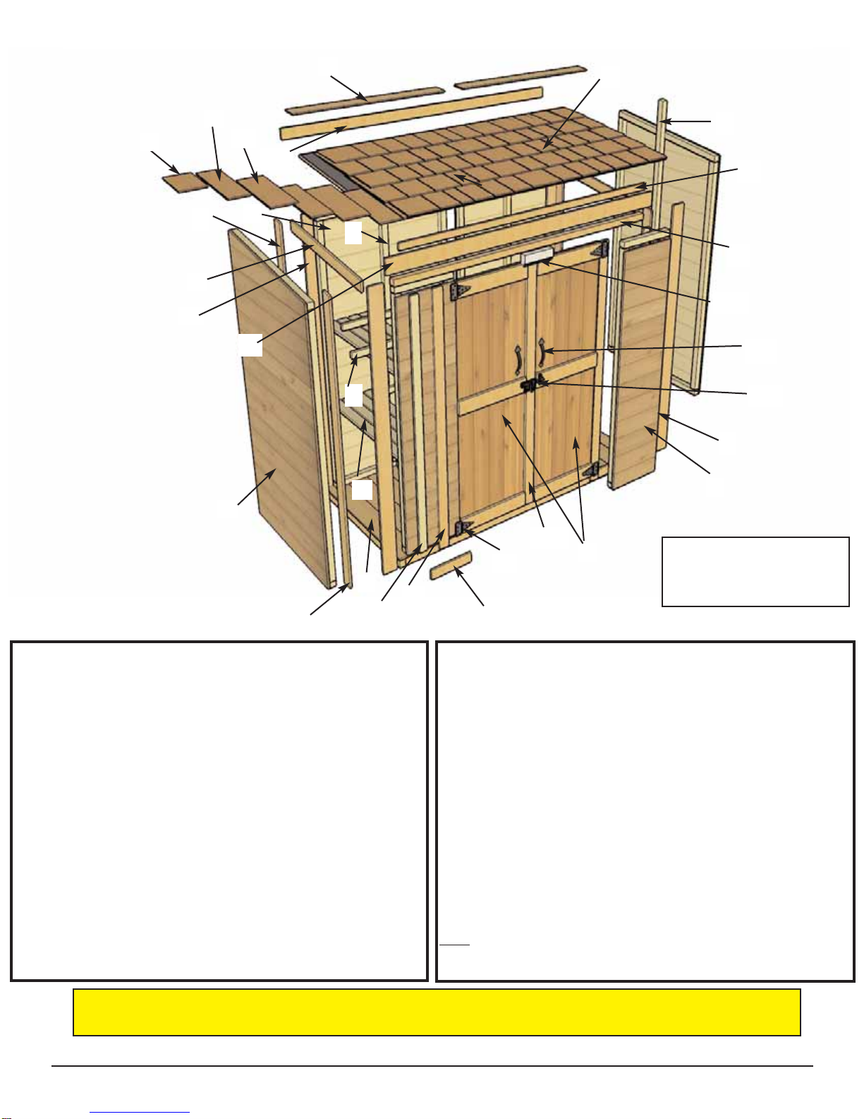
Floor Section
A 1 - Floor Section - 35 1/2” x 74” x 2 1/2”
Wall Section
B 2 - Side Walls - 35” x 70” - Angled Top (One Left / One Right Side)
C 2 - Back wall Panels - 35” x 70” - Identical
D 2 - Side Wall Studs - 1 1/2” x 1 1/2” x 64 1/2” (angle cut one end)
E 2 - Back Wall Studs - 1 1/2” x 1 1/2” x 67”
F 2 - Front Narrow Walls - 14 1/2” x 63 3/4” - Identical
G 1 - Door Header - 1 1/2” x 1 1/2” x 70”
I 2 - Storage Shelf Support - 3/4” x 1 1/2” x 14 1/2” & 18 1/4”
J 2 - Storage Shelves - 3/4” x 11 1/2” x 31 1/4”
Q 2 - Doors - 20 1/4” x 61 1/2” (Door Flange on Left Door)
CC 1 - Lower Door Stop - 3/4” x 1 1/2” x 8” * See Step 41
EE 1 - Upper Door Stop - 1 1/2” x 2 1/2” x 8” with Dado cut
DD 1 - Barrel Bolt Plywood Spacer - 1/2” x 2 1/2 x 2 1/2”
Roof Section
K 1 - Cedar Shingle Roof Panel - 38” x 78”
L 7 - 5” x 16” Shingles (Includes 1 Extra Shingle)
M 5 - 6” x 16” Shingles (Includes 1 Extra Shingle)
N 2 - 6” x 12” Shingles
Z 2 - Roof Ridge Caps - 1/2” x 3 1/2” x 39”
Trim Section
H 1 - Front Horizontal Trim - 1/2” x 3 1/2” x 73 3/4”
O 2 - Vertical Door Frame Trim - 1/2” x 2 1/2” x 64”
R 2 - Front Filler Trims - 1/2” x 1 1/2” x 61 1/2”
S 2 - Front Corner Trims - 1/2” x 3 1/2” x 67 1/2”
T 2 - Front Side Corner Trims - 1/2” x 2 1/2” x 68” - angle cut end
U 2 - Rear Corner Trims - 1/2” x 3 1/2” x 72”
V 2 - Rear Side Corner Trims - 1/2” x 2 1/2” x 70” - angle cut end
W 1 - Rear Center Trim - 1/2” x 2 1/2” x 72”
X 2 - Side Facia Trims - 1/2” x 2 1/2” x 33 1/4” (angle cut both ends)
Y 1 - Front Facia Trim - 1/2” x 1 1/2” x 68”
FF 1 - Upper Rear Trim - 1/2” x 2 1/2” x 75”
GG 2 - Lower Front Narrow Trims - 1/2” x 2 1/2” x 10 3/4”
HH 1 - Door Flange - 1/2” x 2 1/2” x 61 3/8”
** Plus 2 Cedar Shingle Shims (discard after using)
Note: We recommend you drill a 1/8” pilot hole for each screw to avoid
splitting wood. The hole depth should be equal to 3/4 the length of
screw.
A
B
UC
Y
V
S
K
R
D
T
I
Q
J
H
F
G
L
Exploded View and Parts List for 6’x3’ Grand Garden Chalet
O
P
AA
BB
E
M
N
X
Z
Parts List
Note: Trim and Skirting pieces are graded with the best face being rough sawn.
Rough sawn cedar is much easier to paint and stain.
EE
FF
GG
Not Shown:
W - Rear Center Trim
CC- Lower Door Stop
DD-Barrel Bolt Plywood Spacer.
HH