olympia electronics BS-685 User manual

Page 1 from 5921686000_09_017
OPERATION - USE
BS-685 and BS-686 detectors are used in
combination with gas panels to give us a
warning in case there is a natural gas or LPG
gas leak. The installation must be done by a
qualified personnel. Instructions must be read
before the installation.
Emergency Actions
It is recommended that the following advice
should be given in the event of an alarm
sounding or the smell of gas even without an
alarm:
Keep calm, and carry out the following actions,
not necessarily in the order given:
-extinguish all flames, including smoking
material.
- turn off all gas appliances.
- do not switch on or off any electrical equipment,
including the gas detection apparatus.
- turn off the gas supply at the gas main control
and/or ( with a LPG supply) the storage tank.
-open doors and windows to increase
ventilation.
- do not use a telephone in the building where the
presence of a gas is suspected.
If the alarm continues to operate, even after an
alarm resetting action where appropriate, and
the cause of the leak in not apparent and/or
cannot be corrected, vacate the premises and
IMMEDIATELY NOTIFY the gas supplier in
order that the installation may be tested and
made safe, and any necessary repair carried out.
Placement
Depending on the monitored gas, the unit must be
placed with the sensor downwards, 30cm from
the ceiling (for methane, natural gas) or 30cm
from the floor (for propane, LPG). The horizontal
distance should not be more than 4 meters from
the probable gas leak point and the detectors
must not be placed in humid or drafty areas.
It is suggested that the detector is tested for good
operation every 6 months or if it is changed
position.
The unit must should not be sited:
- directly above cooking appliances
- directly above sink
- adjacent to extractor fans
- in any outside location
-where the environmental conditions are outside
the manufacturers operational specification.
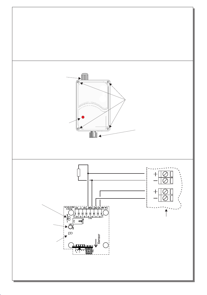
Installation
In order to install the device you must first remove
the four srews (figure 1). Then with the
assisstance of figures 2 and 3 you can connect it
to the panel.
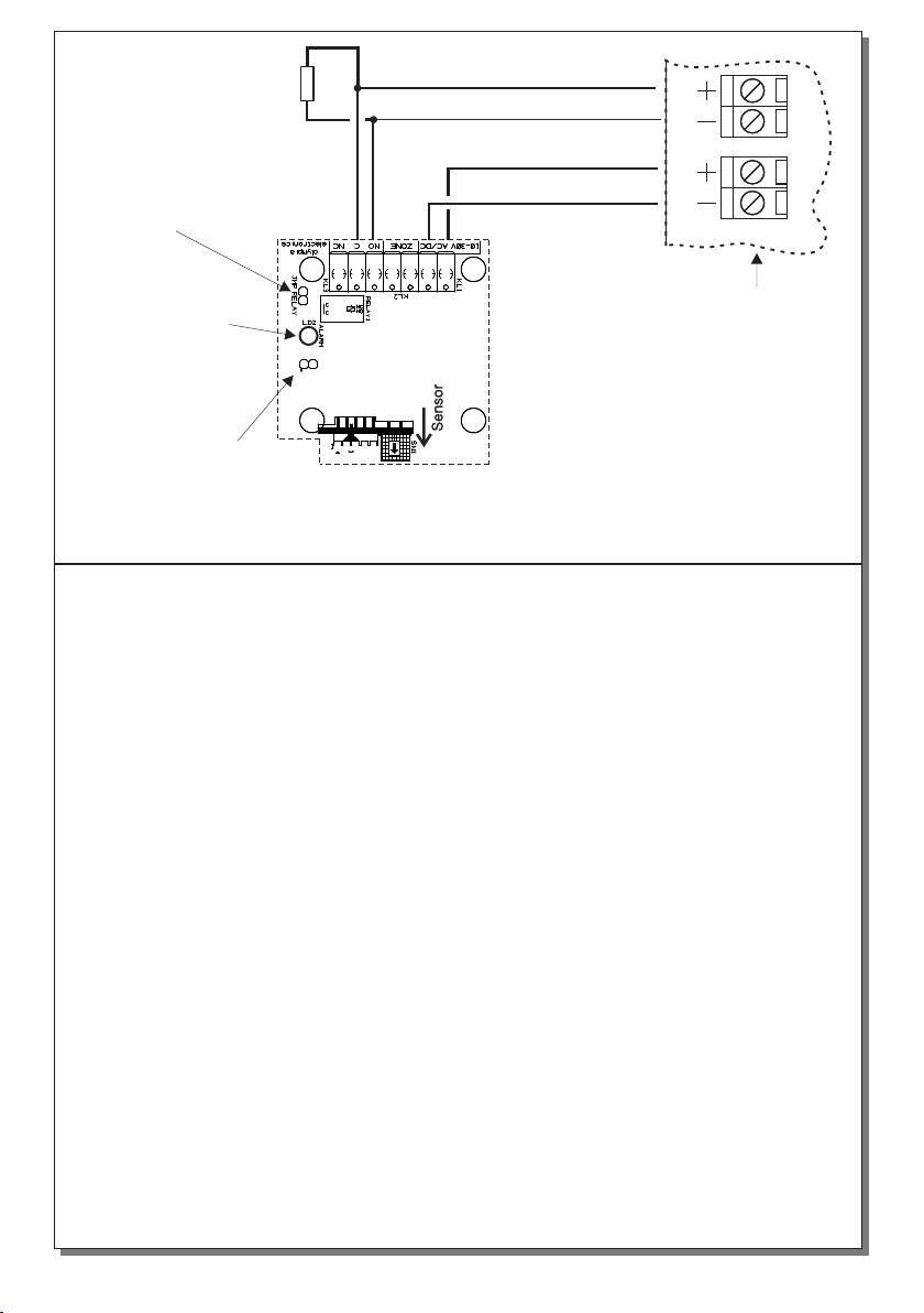
Connection with fire panel of Olympia
Electronics.
Terminals ΖΟΝΕ are used to connect to zone of
the gas panel, as shown in figure 2. A terminal
resistor (5,6KÙ) should be installed on the end of
BS-685 Waterproof LPG detector for conventional panels
BS-686 Waterproof natural gas-methane detector for conventional panels
TECHNICAL CHARACTERISTICS
Thank you for your trust in our products
Olympia Electronics - European manufacturer
Operation voltage
Average consumption
Sensitivity
Indicators
Degrees of cover protection
Produced in accordance with
Operation temperature range
Humidity
Dimensions
Sensor life time
Weight
Guarantee
BS-686BS-685
10-30V AC- DC ( Powered by panel)
0,5W ( 12VDC 40mADC, 24VDC 20mADC)
5-15 % L.E.L. Methane
5-15 % L.E.L. Propane
alarm LED
IP 65
EN 50194-1, EN 50270
o
0 to 60 C
Up to 95% relative humidity
155 x 80 x 43 mm
5 years
150 gr
2 years

Page 2 from 5
the line(see figure 2).
Connection with others fire panel.
Terminals NO, C are used to connect to the zone
of the gas panel, as shown in figure 2. A terminal
resistor should be installed on the end of the line
(see figure 3).
Programming Alarm latch mode
When the device is in alarm mode, it keeps its
condition even if the contents drop below 5-15%
of the L.E.L. This is an alarm latch mode. This
mode is helpful to the technician, to locate the
device which is in alarm condition.
When you connect the device to a conventional
gas panel, the device must have alarm latch
mode. If we want to de-activate the alarm latch
mode, the LD1 jumper must be linked. The link
or the removal should be done when the unit is
not operating. The device is shipped with
activated the alarm latch.
Figure 1. Diagram of removing the plastic cover
Ζ1 24V_M
5Ê6
Terminal Resistor
LED Alarm
Jumper for programming
alarm latch mode
Fire panel
Olympia Electronics
Relay resistance
selection jumper
Figure 2. Connection diagram of a detector
with a fire panel of Olympia Electronics
921686000_09_017
These screws must be
unscrewed in order to remove
the plastic cover
The sensor must
faced downwards
LED Alarm
Gland for cable
connection

Page 3 from 5
Figure 3.
Connection diagram of a detector with a fire panel of other company.
Ζone 10-30VDC
Terminal Resistor
LED Alarm
Jumper for programming
alarm latch mode
Fire panel
Relay resistance
selection jumper
Sensitivity
The BS-685 detectors are activated when the
content of gas (propane), in the monitored area,
exceeds 5 - 15% of the lower explosive level
(L.E.L).
The BS-686 detectors are activated when the
content of gas (methane), in the monitored area,
exceeds 5 - 15% of the lower explosive level
(L.E.L).
The devices are connected to 24_M, of a gas
panel, as shown in figure 2. When a detector is
activated, it gives an alarm signal to the gas
panel. The activation stops when:
A) You push the test button or when you cycle the
power of the detector (Alarm latch mode) (figure
4).
B) You push the test button or the gas content
drops below 5-15% of the L.E.L. (Νο alarm latch
mode) (figure 5).
Indication LEDS and Operation
When first installed, you must wait 20 seconds
until the sensor compensates to its surroundings.
When the red LED is lit then the unit is in alarm
mode. Alarm mode can be triggered from the
sensor of the unit. Figure 4 shows a connection
diagram between 4 BS-685 or BS-686 and a gas
panel.
Waterproofing of the device
The package contains a sealing gasket which is
installed on the rim of the front cover in order to
water-proof the unit.
Relay resistance Selection (JMP RELAY)
There is the capability to select the alarm relays
resistance, with the use of the resistance
selection Jumper. When a link is used on the
jumper, then the used resistance is zero, and an
external resistence may be used. If there is no
link, then the on board resistence of 440 Ohm is
used.
ATTENTION!! The devices must not be
tested using gas filled lighters because the
sensor will be destroyed.
921686000_09_017

Page 4 from 5
Figure 4. Connection of 4 gas detector BS-685 or BS-686 to a
Olympia Electronics panel. The number of the devices connecting
to a gas panel is depending only to the panel specifications.
Ζ1 24V_M
Terminal
Resistance
5Κ6
BS-685-6 BS-685-6
BS-685-6 BS-685-6
Figure 5. Connection diagram with BS-690 (no alarm latch mode)
NC
C
NO
N
+
L
OUT
GND
Z+
Z -
+VS
GND
S
EXTERNAL
BUZZER
Sensor
JMP1
JMP2
JMP3
LN
~230 V
AB
Power LED
RED LED
RED LED
Alarm LED
Fault LED
Button
1
1
1
SENSOR
BS-655
5Κ6
BS-690-1
BS-685-6
921686000_09_017

Page 5 from 5
WARRANTY
Olympia Electronics guarantees the quality, condition and operation of the goods. The period
of warranty is specified in the official catalogue of Olympia Electronics and also in the
technical leaflet, which accompanies each product. This warranty ceases to exist if the buyer
does not follow the technical instructions included in official documents given by Olympia
Electronics or if the buyer modifies the goods provided or has any repairs or re-setting done
by a third party, unless Olympia Electronics has fully agreed to them in writing. Products that
have been damaged can be returned to the premises of our company for repair or
replacement, as long as the warranty period is valid.
Olympia Electronics reserves the right to repair or to replace the returned goods and to or not
charge the buyer depending on the reason of defection. Olympia Electronics reserves the
right to charge or not the buyer the transportation cost.
HEAD OFFICE
72nd km. O.N.R. Thessaloniki-Katerini
P.C. 60300 P.O. Box 06 Εginio Pierias Greece
www.olympia-electronics.gr
921686000_09_017
This manual suits for next models
1
Table of contents
Other olympia electronics Gas Detector manuals
Popular Gas Detector manuals by other brands

Riken Keiki
Riken Keiki PLU-70 operating manual

Oceanus
Oceanus OC-903 operating manual

AGS
AGS Merlin 1500S Installation & operation manual

Tokyo Gas Engineering Solutions Corporation
Tokyo Gas Engineering Solutions Corporation LaserMethane SMART LM2B03N-SBA operating instructions

Dräger
Dräger X-am 2800 Instructions for use

Riken Keiki
Riken Keiki GX-2009 user guide