olympia electronics BS-377/WP/A User manual

GENERAL
The BS-377/WP/A and BS-378/WP/A explosive
gas detectors are used to measure the
concentrations in % L.E.L. (Lower Explosive
L e v e l ) w h i l e s i m u l t a n e o u s l y p r o v i d i n g
autonomous notification/alarm operations in
case there is a leak of liquid on natural gas.
They are used in commercial and small
industrial areas such as professional kitchens
and burner rooms.
The installation must be done by trained
pers onne l tha t has p r evi o usly r ead t he
instruction manual.
In case on an alarm or gas leak:
Keep calm and follow the instruction below
independent of their order.
- Turn off all burning flames and anything that is
smoking.
- Close all gas appliances (kitchens - burners -
cookers etc.)
- Close the central gas supply or canister.
- Open doors and windows in order to ventilate
the area.
Avoid :
- Turning on/off the wall switches or the detector.
-Using a mobile phone in the area that is
Page 1 from 6 921377000_09_007
Thank you for your trust in our products
Olympia Electronics - European manufacturer
BS-377/WP/A Autonomous waterproof liquid gas-LPG detector with relay
BS-378/WP/A Autonomous waterproof natural gas-methane detector with relay
II 3G
Ex ec IIA T6 Gc
TECHNICAL CHARACTERISTICS
OPERATION VOLTAGE
MAXIMUM CONSUMPTION
% L.E.L ALARM
SENSOR TYPE
MEASUREMENT RANGE
SENSOR LIFE SPAN
SENSOR STABILIZATION PERIOD
DURING STARTUP
RESPONSE TIME (Τ90)
REPEATABILITY
MAXIMUM DEVIATION (after calibration)
CHANGE
INDICATORS
OUTPUTS / CONNECTIVITY
197-265V AC
catalytic
0-50 L.E.L.
5 years (*)
60 seconds
<45 seconds
= ±1.5 L.E.L.
≤ ±1.5 L.E.L.
≤ ±4.5 L.E.L./year
Operation LED (green)
Fault LED (yellow)
Alarm LED (red)
Buzzer
Selectable at 10% and 20% L.E.L
3VA (at 230V AC)
OPERATION AND STORAGE
CONDITIONS
EXTERNAL DIMENSIONS
TYPICAL WEIGHT
GUARANTEE
DEGREES OF COVER PROTECTION
PRODUCED IN ACCORDANCE WITH
IP65
EN 60079-29-1, ΕΝ 50270, ΕΝ 50271
o
-10 to 60 C
1 atm ±10%
10 to 95% relative humidity (with no condensation)
2 years (**)
300gr.
145 x 85 x 45 mm
CONSTRUCTION MATERIAL Bayblend FR3010, clear polycarbonate
Alarm relay (24 0VAC / 5A N.O. / 2Α N.C.), latching /non-latching
Input for connecting an external button
(silence buzzer & alarm relay reset)
Fault relay (24 0VAC / 5A N.O.)
(*) = (Ideal condi tions) When the detector is expos ed to cleaning agents, silic ons and generally
in commerc ial and light industrial env ironments, it is recommended to b e calibrated every year
and its sens or to be replaced every 3 years!
ATTENTION!! DO NOT USE LIQUID GAS (i.e. lighter gas) FOR SENSOR TESTING BECAUSE IT
CAUSES PER MANENT DAMAGE. Use calibration gas up to 50% L.E.L. for this purpose.
(**) = does not cover the gas sensor, if it is exposed to Si, H2S, Pb & h alogenated hydrocarbon.

Page 2 from 6 921377000_09_007
suspected to have the gas leak.
If the alarm continues then evacuate the building
and inform the gas supply company.
Mounting
Depending on the gas type that we want to
detect, the device should be mounted with the
sensor pointed downward(maximum allowed
deviation ±20°), 20-30cm from the ceiling (for
methane, natural gas) or 20-30cm from the
floor (for propane, butane, liquid gas, LPG), up
to 4 meters (in a horizontal distance) from
probable leak points and away from air drafts
and humidity.
The detectors must not be placed:
- Near ventilators or near doors and windows.
- In an external area.
- In an area that is located near:
- Corrosives or solvents e.t.c.
- Silicones (e.g. insulation, glues, detergents)
- Sulfuric compounds
- halogenated hydrocarbon.
- Organic phosphoric compounds.
Installation
To mount the device, unfasten the 4 retaining
screws.(figure 1). Next, using the diagram on
figure 2 to realize the external connections of
the system. The device operates with a mains
voltage of 240V AC (with a voltage range of 197
to 265V AC).
ATTENTION!!!
To m a i n t a i n t h e d e g r e e o f I P 6 5 t h e
waterproofing gasket must be fitted to the top of
the chassis of the device. Also after each
opening of the chassis of the device the
condition of the gasket should be checked and
replaced if damage occurs.
Dip-switches settings
The BS-377/WP/A and BS-378/WP/A detectors
(figure 3), have six dip-switches to adjust the
operation mode.
Below you can see these mode settings and
there meaning:
Dip-switch Function
TABLE 1
S1&S2
S3
S4
S5
S6
Dip-switch combinations
Calibration with
clean air
Calibration with
reference gas
Test for outputs
(relay, led, buzzer)
Normal operation
(default)
Latching alarm relay
and red led (defa u l t)
Alarm function at
20% L.E.L.
Alarm function at
10% L.E.L. (defa u l t)
Does not provide any operation
With no latching
Calibration reference gas concentration
50% L.E.L. (Def a u lt)
Calibration reference gas
concentration 20% L.E.L.
S1S2
OFF
OFF
OFF
OFF
OFF
OFF
OFF
ON
ON ON
ON
ON
ON
ON

Page 3 from 6 921377000_09_007
-S1 & S2. These switches determine the
operation of special maintenance and test
functions. To conduct these functions, select the
suitable combination with the switches S1 and
S2 and press the internal button BT2 (figure 3)
for more than 1 second. The function «output
test» activates all the LEDs, the buzzer and the
alarm relay and deactivates the fault relay while
the button is being pressed. For the calibration
function, detailed instructions are given later on
in this manual.
-S3. When the latching function is selected then
when the detector senses a gas concentration
equal to or greater than % L.E.L the alarm relay
and the alarm led (red) remain activated even if
the concentration of % L.E.L. returns to normal
levels. The deactivate them, the external button
LAY 5-BP111 can be used.
-S4. This operation refers to the special
operation calibration function with reference gas.
Via S4 select the concentration of gas that will
be used (20% or 50% L.E.L.)
-S5. This setting refers to the concentration in
% L.E.L. that must be detected in order to
activate the alarm relay, the red led and the
buzzer. 10% or 20% L.E.L can be selected. After
the selection is made, the concentration of gas
that is considered to be normal is below 2.5%
L.E.L. from the selected setting, that is below
7.5% or 17.5% L.E.L. respectively.
L N
(*)
(**)
Figure 1. Interior access, cable entry and indicators
External
Button
LAY 5-BP111
To gain access to the interior remove
these 4 screws
Sensor head located downwards
Cable entry groumet
Operation, Alarm and Fault
Indicator
Capability to install a second
cable groumet
(*) Electro-valve / beacon / siren / power relay.
(**) Electro-valve / beacon / siren / power relay.
Warning!!! The contact is closed during normal
operation and open during a fault.
Figure 2
Figure 3
Load
Load

Page 4 from 6 921377000_09_007
Alarm relay
The alarm relay is activated when the
concentration % L.E.L. of the sensed area
exceeds the alarm level (10% or 20%). The
relay returns to normal operation when the
gas concentration returns to normal levels. If
the latch function has been selected via the
S3 switch, then the relay remains activated
even if the gas levels return to normal. In this
case, to deactivate it, use the external button
LAY 5-BP111 that must be pressed for more
than 2 seconds.
Fault Relay
The fault relay has one contact that is closed
(N.C.) when the system is powered and there
are no malfunctions. This contact opens when
there is no power or there is a malfunction
Buzzer
The buzzer is activated (beeps every second)
when the concentration of % L.E.L. in the
covered area exceed the alarm selected level
(10% or 20%). The buzzer stop automatically
when the gas concentration returns to normal
levels. While the buzzer is activated it can be
silenced using the external button LAY 5-BP111
which must be pressed for more than 2
seconds.
The buzzer is also activated in case of a system
malfunction (5 short beeps with 10 second
pauses in between).
Incase of a simultaneous alarm and error
event, priority is given to the indication of
the alarm event.
Green LED (operation indicator)
The green LED indicates the presence of the
power supply and special operation states as
described in table 2.
Red LED (alarm indicator)
The red LED is activated when the gas
concentration of % L.E.L. in the covered area
exceeds the selected alarm level (10% or
20%). The LED is deactivated when the gas
concentration returns to normal levels. If the
latching function has been selected via the S3
micro switch then the LED remains active
(blinks every second) even if the gas
concentration drops to a safe level. To
deactivate it, use the external button LAY 5-
BP111 that must be pressed for more than 2
seconds.
Yellow LED (Fault indicator)
The yellow LED indicates a system malfunction
or fault and also some special states as shown
in table 3 (page 4).
Yellow LED Operation
Permanently activated
Problem with the system settings.
Repeat the clear air and reference gas calibration
procedure.
Probable cause:
-The power supply of the system is out of operation limits
(in combination with the green led operation).
Check the power supply of the system.
-gas sensor malfunction. Replace sensor.
-Central processor malfunction. Service required.
Explanation
TABLE 3
Intermittent brief
illumination once a minute
The current concentration of gas has exceeded the
high detection limit of the device that is 50% L.E.L.
Normal operation is restored automatically when
the gas concentration drops to within the measuring
limits of the unit.
Intermittent operation
every second
Green LED Operation
Permanently activated
Intermittent operation
every second
The system is powered
Explanation
TABLE 2
The system is in the initialize pre-heat phase
of the sensor.
This phase last for 60 seconds
Intermittent brief
illumination once a minute The supply of the system is out of limits

Page 5 from 6 921377000_09_007
Input for external button LAY 5-BP111
Τhe external button LAY 5-BP111 operates in
o
surrounding temperature: -25~+55 C, the rated
insulation voltage is: 600V AC (50-60Hz) and
the IP rating is: ΙΡ40. The external button can
used to mute/reset the alarm relay, Buzzer and
Red indicator as described in each section.
WARNING!!! The cable length between the
external button and the system must not
exceed three (3) meters.
System Calibration
WARNING!!! The calibration procedure of the
detector must be done by qualified personnel
that have previously read the user manual.
-The special calibration function is not available
to the user if there are faults in the system.
-For the calibration procedure using a reference
gas, the OL-11 calibration kit is required. (figure
4).
-For the calibration procedure using a reference
gas, a mixture 20% or 50% L.E.L. with oxygen
and nitrogen is used. The explosive gas
catalytic sensors do not operate without oxygen.
-It is suggested to conduct the calibration
test at least once every 12 months.
-During the calibration procedure, conduct a
clean air calibration and then a reference gas
calibration.
To calibrate the device, remove the 4 retaining
screws (figure 1) in order to gain access to the
interior.
Clean air calibration
Take the following steps:
1.Ensure that the environment is clean and does
not contain explosive gases.
2.Select using the switches S1 and S2 (figure 3)
the special function «Clean air calibration»
3. Press the button BT2 (figure 3) for more than
3 seconds until the 3 system LEDs(green,red
and yellow) start to blink with a one second rate.
4.Wait 4 seconds until the procedure is
completed. This step may last 60 seconds
more in some instances.
When the procedure is finished, the yellow led
a n d t h e b u z z e r o p e r a t e i n t e r m i t t e n t l y.
(intermittent brief activation every second).
At this point there are two instances:
-The green led is lit. This means that the clean
air calibration has finished with success. Press
and hold the button ΒΤ2 for more than 1 second
to exit calibration mode and to return the
detector to normal operation.
-The red led is lit. The clean air calibration
procedure did not finish successfully. Press and
hold the button BT2 for more than 1 second to
exit calibration mode and to return to normal
operation. You can repeat the process by
following the steps from the beginning.
Calibration using a reference gas
The steps for calibrating using a reference gas
are the following:
1. Ensure that the environment is clean an free
from explosive gases.
2.Remove the gland with the filter located on the
sensor head (figure 1).
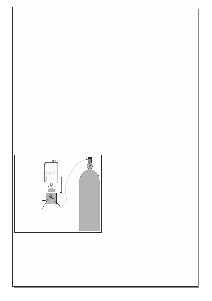
3. In its position install the accessory OL-11-1 of
the calibration kit OL-11 (figure 4).
4. Install the part OL-11-2 on the part OL-11-1
(figure 4).
5. Select via the micro-switch S4 (figure 3) the
concentration of the reference calibration gas
that will be used (20% or 50% L.E.L.).
6. Select via the micro-switches S1 and S2
(figure 3) the special operation «Calibration with
a reference gas».
7. Press and hold the button BT2 (figure 3) for
more than 3 seconds until the 3 system LEDs
( g r e e n , r e d a n d y e l l o w ) s t a r t t o b l i n k
(intermittent blink once a second) and then
release the button.
8. Open the steady pressure valve (0.3L /
minute) of the reference gas canister.
9. Wait 3 minutes until the procedure finishes.
This step may last 60 seconds more in some
instances.
While waiting for the procedure to complete
you can cancel it at any time by pressing the
Bt2 button for more than 3 seconds.
When the procedure is finished, the yellow led
a n d t h e b u z z e r o p e r a t e i n t e r m i t t e n t l y.
(intermittent brief activation every second).
At this point close the flow valve on the gas
canister.
At this point there are two instances:
-The green led is lit. This means that the
reference gas calibration procedure has finished
with success. Press and hold the button ΒΤ2 for
more than 1 second to exit calibration mode and
to return the detector to normal operation.
-The red led is lit. The reference gas calibration
procedure did not finish successfully. Press and
hold the button BT2 for more than 1 second to
Gas
Canister
Detector
Adapter
OL-11-1
Outlet
port
figure 4
OL-11-2
Inlet
port

Page 6 from 6 921377000_09_007
exit calibration mode and to return to normal
operation. You can repeat the process by
following the steps from the beginning.
After the calibration procedure is finished and
before normal operation remove the part OL-11-
2, unscrew the part OL-11-1 and reinstall the
gland with filter to the sensor head.
WARRANTY
Olympia Electronics guarantees the quality, condition and operation of the goods. The period of
warranty is specified in the official catalogue of Olympia Electronics and also in the technical leaflet,
which accompanies each product. This warranty ceases to exist if the buyer does not follow the
technical instructions included in official documents given by Olympia Electronics or if the buyer
modifies the goods provided or has any repairs or re-setting done by a third party, unless Olympia
Electronics has fully agreed to them in writing. Products that have been damaged can be returned to
the premises of our company for repair or replacement, as long as the warranty period is valid.
Olympia Electronics reserves the right to repair or to replace the returned goods and to or not charge
the buyer depending on the reason of defection. Olympia Electronics reserves the right to charge or
not the buyer the transportation cost.
HEAD OFFICE
72nd km. O.N.R. Thessaloniki-Katerini
P.C. 60300 P.O. Box 06 Εginio Pierias Greece
www.olympia-electronics.gr
This manual suits for next models
1
Table of contents
Other olympia electronics Gas Detector manuals
Popular Gas Detector manuals by other brands

GASTRON
GASTRON GPD-100 instruction manual

MSA
MSA ALTAIRE 4X user manual

Joy-it
Joy-it SEN-MQ4 manual

Riken Keiki
Riken Keiki 9000 Series operating manual

ESYLUX
ESYLUX PROTECTOR CD 45 manual

Tokyo Gas Engineering Solutions Corporation
Tokyo Gas Engineering Solutions Corporation LaserMethane SMART LM2B03N-SBA operating instructions