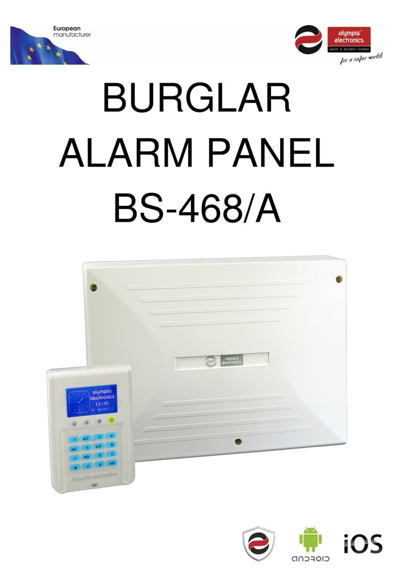
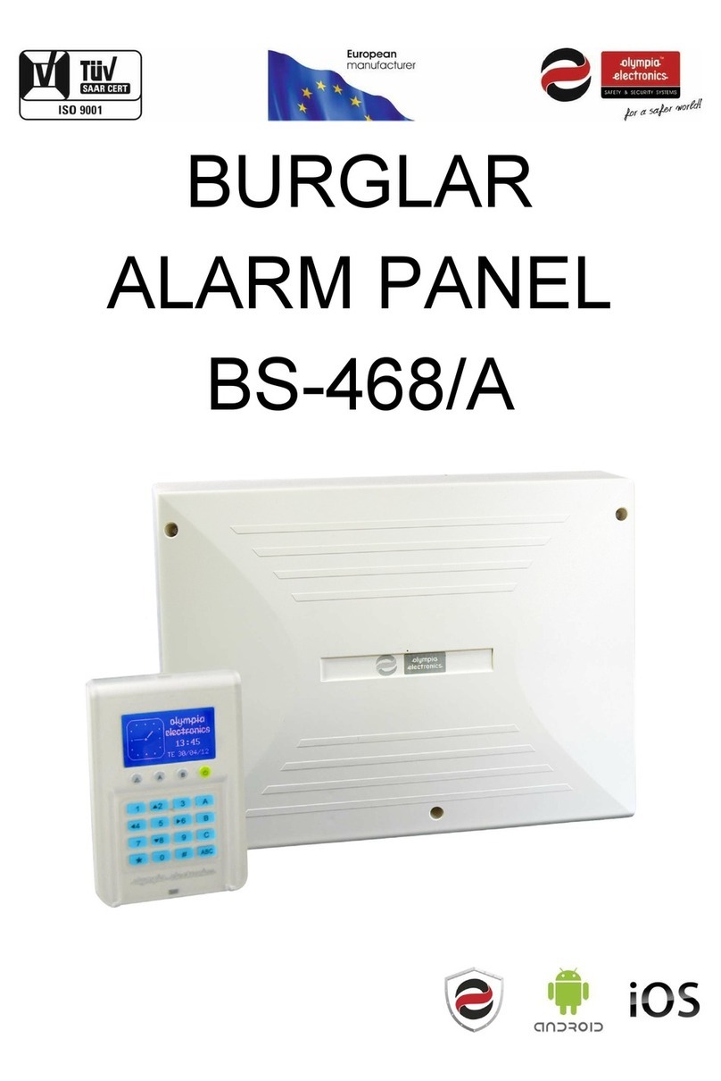
olympia electronics BS-468/A User manual

WIRELESS BURGLAR ALARM SYSTEM
BS-468/A
QUICK INSTALLATION GUIDE

Page 2 921468007_90_005
Contents
1. BEFORE INSTALLATION................................................................................................. 4
1.1 GENERAL INFORMATION................................................................................................. 4
1.2 What includes the wireless KIT BS-468/A/Kit.................................................................. 5
1.3 Starting the installation................................................................................................... 5
1.4 Installation methods........................................................................................................ 6
2. DETECTION OF NETWORK’S DEVICES ............................................................................7
2.1 WIRELESS KEYPAD DETECTION........................................................................................ 7
2.2 DETECTION OF WIRELESS DEVICES.................................................................................. 8
3. DEVICE’S INSTALLATION...............................................................................................9
3.1 RANGE TESTING USING WIRELESS KEYPAD..................................................................... 9
3.2 FINAL PLACEMENT OF WIRELESS DEVICES...................................................................... 9
4. STARTING UP THE INSTALLED SYSTEM ........................................................................ 10
4.1 SYSTEM CONFIGURATION ............................................................................................. 10
4.2 INSTALLATION COMPLETION......................................................................................... 11
5. DEVICES INSTALLATION.............................................................................................. 11
5.1 Generals......................................................................................................................... 11
5.2 Device’s control operation ............................................................................................ 12
6. BASIC SYSTEM CONFIGURATION................................................................................. 12
6.1 Zone settings ................................................................................................................. 12
6.2 Section configuration .................................................................................................... 12
6.3 Entrance, exit, extra time settings................................................................................. 13
6.4 Zones bypass –forced arm............................................................................................ 13
7. HANDLING THE SYSTEM WITH THE WIRELESS KEYPAD................................................. 14
7.1 Key Operations and Functions of the Wireless Keyboard............................................. 14
7.2 Basic Menu .................................................................................................................... 15
7.3 Wireless keypad activation............................................................................................ 16
7.4 Basic handling and settings ........................................................................................... 16
7.5 Advanced Operations.................................................................................................... 18
7.6 Wireless Zones Events................................................................................................... 20

Page 3 921468007_90_005
8. BS-468/A REMOTE CONTROL...................................................................................... 20
8.1 General .......................................................................................................................... 20
8.2 Installation..................................................................................................................... 21
8.3 Codes registration procedure on rf-467........................................................................ 21
8.4 CODES DELETION PROCEDURE ON RF-467.................................................................... 22
9. System’s app.............................................................................................................. 22
9.1 Program for PC PC-468/A.............................................................................................. 22
9.2 Mobile app i-olympia (Android & iOS) .......................................................................... 22
10. Alarm’s faults........................................................................................................... 23
11. Warranty ................................................................................................................. 24

Page 4 921468007_90_005
1. BEFORE INSTALLATION
1.1 GENERAL INFORMATION
Thank you for choosing an Olympia Electronics product to protect your property. The
set of wireless alarm devices included on the kit is suitable for apartments, small
two-storey houses and small business premises. This guide will help you recognize
the enclosed devices and understand your system setup. In order to install BS-468/A
system, you do not need any special technical knowledge, as long as you follow the
instructions in this document. For any further information in addition to this manual,
please refer to the BS-468/A manual which is also enclosed within the kit as well as
the instructions for the individual devices that are enclosed in the packaging of each
device. You should keep in mind that during the installation procedure the wireless
keyboard should not be left unnecessarily active in the technician menu. For every
half hour that its screen is active (the average time needed to keep it turned on
during the installation process), it costs about 10 days of its autonomy. This manual
will mention you when you need to turn the wireless keyboard on or off.
Whenever the user sees this special symbol followed by the words “NOTE” or
“CAUTION” then special attention should be paid to this point.

Page 5 921468007_90_005
1.2 What is included inside the wireless KIT BS-468/A/Kit
NOTE: Applies only if you have purchased this Kit.
BS-468/A Burglar alarm panel 8 zones
1 PC
BS-470 Wireless PIR motion sensor
1 PC
BS-429/W Magnetic trap for burglar alarm (white) NC
2 PCS
BS-471 Wireless magnetic door detector
1 PC
BS-475/B Wireless siren in charcoal colour
1 PC
BS-477/SL Wireless keyboard for BS-468/A burglar alarm panel
1 PC
BS-479 32 wireless zone expansion module for BS-468/A
1 PC
RF-467 Remote control transmitter 433MHz for BS-468, BS-468/A panel
2 PCS
YET205B-630 MODULE RECEIVER 433MHz,RECEIVER MODULE,4 CODES, 1 OUTPUT
PER CODE
1 PC
A-986 12V 12V/7Ah sealed lead acid battery
1 PC
1.3 Starting the installation
Make sure the BS-479 extension is mounted on the panel. All the wireless peripheral
devices (traps, radars, sirens, keyboards) do not have their batteries installed. We
place the BS-468/A board in the position we have chosen for installation and connect
it to the mains supply, according to the following diagram.

Page 6 921468007_90_005
1.4 Installation methods
BS-468/A comes with factory predefined codes for:
User (Master): 1-2-3-4
Installer-Technician: 9-9-9-9
A. PC
To proceed with installation through a computer, please refer to the user manual
Section 3.6 "Programming via computer".
B. BS-466/A wired Keyboard
The installation process through the wired keyboard is the same as that of the
wireless keyboard in steps 3 and 5 (see installation mode C).
C. BS-479 wireless extension and BS-477 Wireless Keyboard
NOTE: For basic and specialized keyboard operations and panel's settings,
please refer to "Section 4" of this guide.

Page 7 921468007_90_005
2. DETECTION OF NETWORK’S DEVICES
2.1 Wireless keypad detection
CAUTION: The choice of placing the panel is very important for the signal’s
strength, because all the other devices are communicating with the panel. Avoid
(especially in big places) to place the panel to terminal places, where the distances
with some devices are big. Also, avoid placing close to metal surfaces or behind thick
walls. They are suggested places near to the center of the protected area.
NOTE: If you have purchased the wireless kit, then the BS-477 wireless
Keypad inside the kit is already synchronized with BS-468/A panel. You only need to
install all the other devices from the BS-477 menu. If you have purchased the panel
with the Keypad separately, then you must first synchronize the keyboard with the
panel and then install the rest of the devices from the BS-477 keypad. Below the
whole procedure is described. If you have purchased the whole kit, then you must
directly go to step 2.
The procedure must be done before the installation of any other device. The
procedure is simple and it is performed using 1 push-button of the BS-479 expansion
card. The process is separated into 2 parts. The first part includes the devices
detection and the second installs a wireless keypad. When the BS-477 wireless
keypad is installed, the installation of the other devices can be completed by the
keypad menu. In order to continue, focus on the BT1 button and the LD4 LED (green)
of the BS-479 card. The total time of the STEP 1 procedure is about 2 minutes.
First, the BS-468/A panel should recognize the BS-479 wireless zone extension. This
search includes all connected devices, extensions and wired keyboards. The BS-477
batteries that will occupy zone 25 must not be installed and the tamper must not be
depressed. The procedure is as follows:
1. Connect the panel to the mains and wait for 30 seconds to initialize. LD4 (green)
is off at this stage.
2. Press button BT1 for about 3 seconds until LD4 lights up. Then release the
button.
3. Wait about 60 seconds until LD4 starts blinking, indicating that device scanning is
completed.
4. Insert the batteries into the BS-477 keypad. The panel detect it and will import it
to its network. At the same time the LD4 will go out.
5. Wait for about 15 seconds in order BS-477 screen and LEDs are refreshed. BS-
477 Keypad installation has been completed. The other devices can now be
identified by the keypad's technician menu.
6. End of procedure.
NOTES:
i. During the above procedure, do not attempt to add another device to the
network (e.g. siren, magnetic contact, etc.) other than the keypad. No other

Page 8 921468007_90_005
DETECTING DEVICE
PRESS ΄#΄TO RETURN
087 01
device should have the battery connected as long as the above procedure is
running.
ii. The keypad detection process has a 1-minute timeout period, since the LD4
starts flashing. If no keypad is inserted for 1 minute, LD4 will go out. To start the
procedure again, the BT1 button must be pressed again.
iii. When the keypad is successfully installed at zone 25, it will be OFF. To switch it
on, go to the technician's "ZONES" menu. This happens because the tamper is
not pressed, so the panel will raise an alarm event. As a result, if a wired siren is
connected to it, it will be triggered.
iv. In case only a wireless keypad is installed and the user tries to connect a wired
keypad to the system, there will be no communication with the panel. In order
to make it operational, the user has to proceed to "SCAN KEYBOARDS" through
the technician menu.
v. As soon as the panel detects the wireless keypad it will erase all wireless zones
and will insert the new keypad into zone 25.
2.2 Detection of wireless devices
Below are described all the necessary steps in order to install wireless devices in the
panel. This process is carried out by the menu "NETWORK INSTALLATION".
1. Press "*". Go to "MASTER OR TECH MENU". By entering the technician code,
the user has now "TECHNICIAN" privileges.
2. Go to "WIRELESS NETWORK". Press "*". Choose "NETWORK INSTALLATION"
and the wireless devices detection starts. At the
bottom left corner of the screen there is a counter
counting the seconds. After 999 seconds, if no device
is added, the installation process stops
automatically. After each introduction of a new
device it starts to count from the beginning. The
bottom right corner gives the number of devices
already installed on the network.
3. To add a device to this system, the user needs to place the battery in the specific
device, push the tamper spring for 1 - 2 seconds and then
release it. If successful, the message will pop up and then the
3-line screen to the left will appear. In the upper line there is
the zone number the device has been inserted to (25 in this
example). The middle line shows the type of wireless device.
The bottom line contains the unique address of the added
device (in our case 0300010F). Note that as long as this
screen is printed for 10 seconds, no other device can be
added to the network.
4. After a few seconds the installation screen reappears and the user can add other
device if needed in the same way. After adding a device, it takes 10 seconds for a
next device to be recognized.
25
BS-477
0300010F

Page 9 921468007_90_005
5. If 32 devices are already installed and a user tries to add another, 4 long beeps
will be heard. No other devices can be installed.
6. By pressing "#ESC"the installation procedure stops.
NOTE: For every change in the wireless zone menu and during the extensions
scan, an amount of time is needed in order to update the data of the wireless
system. During this time, when we try to enter a menu, a waiting message appears.
When the update process is complete, the menus can be used as usual.
NOTE: The above process could be followed with another way as well.
First mount all the devices with their batteries to their positions and then enter the
network installation menu. The devices will be automatically installed in 5-10
minutes. If you would like to speed up the process, you can go and press the tamper
in the devices one by one.
3. DEVICE’S INSTALLATION
3.1 Range testing using wireless keypad
By choosing "SIGNAL STRENGTH" the technician can move to each device's position
and check the signal strength at the specific location.
By entering the technician menu, go to "WIRELESS NETWORK" "SIGNAL
STRENGTH". The value shown on the screen is the signal strength on the specific
position. This value is refreshed every few seconds. When refresh occurs, 4 flashing
dots appear on screen. Prices above 30 means good signal, 19 to 30 average signal,
and below 19 means "low signal". Beyond this value communication is possible, but
there will be a large number of lost packets. It is not recommended to install a device
when the mark is below 20. If at some point there is insufficient signal for a device,
think of a better place to place the panel. The position of the panel is of key
importance for the quality of the wireless network. It is suggested to wait 10-20
seconds at each point to see that the signal is not fluctuating. The 4 dashes at the
bottom of the screen should be also blinking regularly. Note that any presence of
material between the device and the board will affect the signal strength to a
greater or lesser extent, depending on the material. Do not place the panel in metal
or behind metal-covered areas.
3.2 Final placement of wireless devices
❖Remove the batteries from all devices except the wireless keypad. Press "#ESC"
to return to the home screen and let it turn off in order to save battery power.
❖Place every wireless device on its final place (e.g. magnetic traps on doors, siren
on outer space, etc). Activate the wireless keypad with the touch of your palm
and enter the technician menu. Put the batteries on all devices and close their
lids. The user can refer to each device's instruction manual separately. Be aware

Page 10 921468007_90_005
of the correct dip switches position. In infrared sensors the dip switches adjust
the sensitivity and whether the zone is with or without delay. On magnetic
sensors the switches adjust the zone delay and the internal sensor activation (in
case the user wants to connect external). For delayed alarm selection, the dip
switch 1 must be ON in the BS-470, while in the BS-471 the dip switch 2 must be
in the ON position. For more details on these switches and for connecting
external magnetic contacts, refer to the manuals of these devices.
❖Check every device's signal strength by selecting "MASTER OR TECH MENU"
"WIRELESS NETWORK" "VIEW DEVICE". "RSSI" indicates the signal strength of
the wireless zone in a range of 1 to 4. See also some practical tips in SECTION 2
below.
❖Check the tamper springs and sensors of all devices from the keypad and make
sure that all devices are inserted into the panel's network.
("MASTER OR TECH MENU" "WIRELESS NETWORK" "WIRELESS TAMPERS"
or "WIRELESS SENSORS")
▪WIRELESS TAMPERS
This feature allows the user to monitor in real time whether the tamper
spring of each wireless device installed on the network is pressed or not. The
numbers displayed are the wireless zones tamper states. Press and release
the tamper springs one by one and observe the corresponding zone indicator
turning off for a few seconds (while spring is pressed down) or on (spring is
released).
▪WIRELESS SENSORS
This feature allows the user to monitor in real time, whether the sensor of a
wireless device that is installed on the network is activated or not. The
numbers displayed are the wireless zones that give a sensor activation signal.
NOTE: On the wireless keypad, this display has a delay of up to 4
seconds once the device has changed its status.
4. STARTING UP THE INSTALLED SYSTEM
4.1 System configuration
Perform all settings for zones ("MASTER OR TECH MENU" 9 9 9 9 "ZONES"),
entry time, exit time, extra time and the time and date of the system ("MASTER OR
TECH MENU" 9 9 9 9 "SETTINGS"). See also some practical tips in SECTION 3
below.
Connect the battery to the panel. There are two wires, red and black for connecting
to the positive and negative poles, respectively. Once connected, return to the

Page 11 921468007_90_005
home screen and then enter the user menu. Now it is time to change the Master
user code from "1234" to another of your choice. This code will be used to arm and
disarm the whole system when exiting or entering the guarded area. This is done by
selecting "MASTER OR TECH MENU" 1 2 3 4 "CODES" "CHANGE MAIN
PASSWORD". Through the "CHANGE PASSWORD" option the user can create or
change user's codes.
4.2 Installation completion
All the above steps were the main settings in order to make a system operational.
The user can also refer to the technical manual in order to enter extra passwords, to
put automated timer operations and use the system's outputs (e.g. to turn on lamps
in some events or to drive external sirens). If you have purchased a GSM or PSTN
extension, refer to the corresponding paragraphs of the BS-468/A technical manual,
as well as these devices' manuals, to install them on the system. The installation
procedure has come to its end. You have set up an operating system and you know
all the basic details to operate this system. You can try an arm - disarm test to check
that this function is running properly.
CAUTION!!! For optimal system operation, when entering a password either
to enter or exit the guarded area, do not type something on the keypad or open -
close doors or windows, while the message "PLEASE WAIT" appears. Wait for the
message to disappear and make sure the system responded correctly to the code
(e.g., the exit countdown was started or the timer has stopped after input).
5. DEVICES INSTALLATION
5.1 Generals
CAUTION: If the user leaves the technician menu during installation, then an
alarm will be raised and heard from the siren if some device has its tamper spring
free. When leaving the technician menu, the siren will not sound for existing alarms
(e.g. already activated tampers). If no key is pressed for 15 minutes on the wireless
keypad, the keypad will return to the home screen itself (by going out of the tech
menu) and turn off the screen.

Page 12 921468007_90_005
INSTALLATION PROCEDURE: For the best possible ease and speed, have the devices
in front of you. Put the BS-468/A panel in installation mode and place the batteries
one at a time on the devices, followed by tamper press and release after each
battery installation. When you get the message that the device has entered a zone,
proceed to the next device until you complete with all the devices. When you finish,
you can install the devices in place (e.g. the magnetic traps are placed on the doors
and windows and so on).
5.2 Device’s control operation
1. From the corresponding menu, check each device's signal strength, which should
be at least 2/4 to be considered satisfactory.
2. Check the tampers. You should leave the menu only when it says "ALL ZONES
ARE OK". If a zone flashes, you should check the specific device's tamper. Be
careful if a zone is in "Disabled - Off" mode. The tamper alert never flashes even
if it exists.
3. As far as magnetic sensors are concerned, open the door or window on each one
of them, watching the keypad's screen changing. As of PIR sensors (radars), pass
in front of the radar to see if the red LED on the radar lights up and the keypad
screen changes. Let it be noted that radars turn on the LED on each activation,
only in the technician menu. Be careful if a zone is in "Disabled - Off" mode. The
sensor activation alert never flashes even if it exists.
6. BASIC SYSTEM CONFIGURATION
6.1 Zone settings
The entry - exit points of the guarded space must be set as "Zone with delay", for
the user to have enough seconds to disarm the system. Whether they are magnetic
contacts on doors, or motion detectors that see these doors or magnetic connectors
connected to the external input of one of the devices, they must have a delay. The
remaining windows and doors, either infrared or magnetic sensors, can be set as
zones without delay. If these sensors are triggered in an armed system, they will
immediately give alarm signal. If a zone is set as "Disabled - off", it means that the
specific device cannot give an alarm. Keep a note that "zone bell" has no power for
the wireless zones, which do not cause a bell event, regardless of the bell menu
selection.
6.2 Section configuration
If a user wants to have an armed system while being inside the guarded area, then
the magnetic contacts must be in a different section from the motion sensors, so
that only the magnetic devices' section is armed. When you leave the guarded area,
you can arm all areas normally.

Page 13 921468007_90_005
6.3 Entrance, exit, extra time settings
The exit time must be sufficient enough for the user to leave the guarded area
before the system arms. Entry time should be enough for the user to enter the
password for system disarm. It is advisable not to be marginal, in case of accidentally
mistyped passwords. If a password is typed from a wireless keypad, an extra 5
seconds should be taken care of, in order to open and unlock the keypad. It is
suggested that the input time is not less than 30 seconds when a wireless keyboard
is used. As far as the extra time is concerned, it may be necessary for some zone to
take extra time from the normal delay. For example, if some user needs to arm the
system, but also needs to leave with the car from the garage, he could set the garage
door zone as a "NEXT DELAY" zone and set its extra time by "TECHNICIAN MENU"
"SETTINGS" "EXTRA EXIT TIME". This additional time is also added when entering
in an armed system. This extra time is rarely used. It is suggested that "NEXT DELAY"
zones to be placed in a separate section. So some user could have one section with
motion sensors, one with magnetic sensors set to "NEXT DELAY" and one with the
other magnetic sensors.
6.4 Zones bypass –forced arm
It is suggested that motion sensors have the following options during setup: Bypass
= "NO", Forced Arm = "YES". In that way the user can arm the system, bypassing
them, but as soon as he leaves, the devices are able to give an alarm event. As far as
magnetic contacts are concerned, they are usually chosen not to be bypassed, in
order to prevent the system from arming and notify the user to secure those zones
(close an open window). The setting for this is Bypass = "NO" and Forced Arm =
"NO". The keypad notifies the user one-by-one for zones that do not let the system
arm. When all doors and windows are closed, the system starts the exit countdown
without having to re-enter the password. If a user wants to be able to leave a
window open when the system is armed, then the "FORCED ARM" option for this
zone should be selected "YES".

Page 14 921468007_90_005
7. HANDLING THE SYSTEM WITH THE WIRELESS KEYPAD
7.1 Key Operations and Functions of the Wireless Keyboard

Page 15 921468007_90_005
______SETTINGS______
ARM WITH TECH. CODE
DAY OF WEEK SETTING
DATE SETTING
TIME SETTING
BUZZER SETTING
__TECHNICIAN MENU__
EVENTS
CODES
SETTINGS
TIMERS
ZONES
WIRED ZONE CONDITION
OUTPUTS
SYSTEM
PSTN
GSM
WIRELESS NETWORK
FACTORY MENU
_WIRELESS NETWORK_
VIEW DEVICE
ASSIGN ZONE
NETWORK INSTALLATION
DELETE SINGLE ZONE
DELETE ALL ZONES
RF COMM SUPERVISION
WIRELESS TAMPERS
WIRELESS SENSORS
SIGNAL STRENGTH
SIREN LED SETTING
RF MASTER INFO
7.2 Basic Menu
Password Password
9-9-9-9 1-2-3-4
______MEΝU______
BYPASS ZONES
BYPASS W/LESS ZONES
MASTER OR TECH MENU
WIRED ZONE CONDITION
WLESS ZONE CONDITION
LAST ALARMS*
ALL EVENTS
MANUAL OUTPUTS CHECK
INFORMATION
*(Appears only when
there are alarms)
__MASTER MENU__
EVENTS
CODES
SETTINGS
TIMERS
RESET

Page 16 921468007_90_005
7.3 Wireless keypad activation
Cases where the screen remains open are:
a) In the technician menu and user menu.
b) If countdown is in progress (entry or exit time).
c) When activated and the siren sounds, it will remain active for as long as it sounds.
d) When the key is pressed, the time before the display is turned off is renewed.
e) When it detects the user's hand close although there is no key pressed.
f) When a code is entered for arming - disarming or for entering a menu.
When the LCD screen of the device is turned off, it is enough to slightly press the
keys with the palm to activate it. As soon as it is switched on, the key illumination is
on too. At this stage the keys are locked, and every three seconds a message
prompts the user to press the "*" key to unlock the keypad. Until this key is pressed,
no other key is activated if it is pressed and the buzzer does not sound when the
keys are pressed. Once "*" is pressed, the keypad is unlocked and the buzzer will
now sound when a key is pressed. When the keyboard unlocks, the symbol (✔) is
displayed for a while, indicating that the keypad was unlocked.
IMPORTANT: The panic button is detected even when the keypad is locked.
Therefore, once the device is switched on, it is not necessary for the user to press
"*" first, but can press "#" for 5 seconds and send a panic alarm.
7.4 Basic handling and settings
The panel has 1 main code (master code) which by default is set to "1 2 3 4" and up-
to 50 user codes which by default are not programmed. The system can operate in
two different modes. Depending on the mode of operation, the arm and disarm
operations differ.
Arm, disarm, silent alarm and panic alarm on BS-468/A can be activated through RF-
467 telecontrol, which is given (2 pieces) preinstalled. For more information
regarding the installation and usage of these devices, please refer to last 3 pages of
this guide.
Complete System
In this case the system arms and disarms altogether.
Arming can be achieved by using the master code or one of the user codes. The
arming of the system can also be succeeded by simply pressing the ABC key, if during
the installation, the option "ARM WITHOUT CODE" has been selected.
Disarming can be achieved by entering the master code or one of the user codes.
Split System
In this case the system operates as three independent subsystems. You can arm and
disarm the whole system or each subsystem independent from the others.
Arming of the whole system can be done by using the master code or one of the
user codes that have been programmed for general arming. The arming of the

Page 17 921468007_90_005
system can also be done by simply pressing the ABC key, if during the installation,
the option "ARM WITHOUT CODE" has been selected.
The disarming of the system can be done by using the master code or one of the
user codes that have been programmed for general disarming.
The individual arming of the subsystems Α, Β, C can be done by pressing one of the
user codes that have been programmed to arm each subsystem. The arming can also
be achieved by pressing one of the Α, Βor C keys, if during the installation, the
option "ARM WITHOUT CODE" has been selected. The arming of one subsystem does
not affect the status (armed - disarmed) of the other subsystems.
The individual disarming of the subsystems Α, Β, C can be done by pressing one of
the user codes that have been programmed to disarm each subsystem. The arming
of one subsystem does not affect the status (armed-disarmed) of the other
subsystems.
If during the arming procedure a zone is active then the keyboard shows the
message:
Which means that on zone 5 (Kitchen) a window has
been left open.
If we press " # " the arm command is canceled.
If we press " * " or close the kitchen window we see:
This message is shown for 1 second and immediately the arming process starts.
Armed System Indication
When the system is armed, then next to the clock,
instead of the Olympia electronics logo there is a lock
symbol. Next to the lock symbol we can see which
sections are armed. In this example we can see that
the system is partially armed because only the C
section is armed. If the system was fully armed then
the symbols Α, Β, C would have been displayed.
When the system is disarmed, the lock is removed and the Olympia electronics logo
is displayed once gain.
C
SYSTEM CAN NOT ARM
ZONE 05
KITCHEN
*: BYPASS ZONE
#: CANCEL
ZONES BYPASSED
READY TO ARM

Page 18 921468007_90_005
7.5 Advanced Operations
By pressing the (*) key, the screen shows:
Using the up and down keys (keys 2 and 8), we can
move the cursor upwards or downwards. By using
the (*) key the user can achieve the required
selection. By using (#), the user can go one level
backwards or cancel a selection.
Selecting "BYPASS ZONES" we see:
The user can select which zones are disabled (will not
be armed) during the next arming of the system. For
example, if we enter 04 and then immediately 07,
this means that the next time the system is armed,
zones 4 and 7 will be disabled. If a zone blinks, this
means that it is preventing the system from arming.
If it is blackened then this means that it is disabled. If
it is blinking and blackened then this means that it is
disabled but would prevent the panel from arming if it was not disabled.
Selecting "BYPASS W/LESS ZONES" we see:
The same applies for wireless zones. The only
difference is that the zone numbers are 25 - 56
(wireless zones).
Selecting "WIRED ZONE CONDITION":
In the following window we can test the good
operation of the zones and the devices connected to
them. For examples, if a magnetic contact of a
window is connected to zone 4 and the window
opens then the message of the display from "ALL
ZONES OK" will be erased and the indication 04 will
start blinking. As soon as the window closes, the
MENU
BYPASS ZONES
BYPASS W/LESS ZONES
MASTER OR TECH MENU
WIRED ZONE CONDITION
WLESS ZONE CONDITION
LAST ALARMS
ALL EVENTS
MANUAL OUTPUTS CHECK
INFORMATION
____BYPASS ZONES ____
04 07
_____________________
CHOOSE FROM 01-24
BYPASS: --
WIRED ZONE CONDITION
ALL ZONES OK
____ BYPASS ZONES____
29 31
_____________________
BYPASS: -- (25-56)

Page 19 921468007_90_005
screen will display the previous message "ALL ZONES OK". With this method we can
test the good operation of all the detectors and magnetic contacts.
The same applies to "WLESS ZONE CONDITION", except the fact that the menu is
dedicated to wireless zones.
By pressing "LAST ALARMS", the user can examine the alarms that were triggered
during the last arming of the system. The display will be like the one below:
This means that an alarm was triggered for zone 8
which is a TAMPER zone (24 hour operation). The
alarm was issued on 12:20 on 07 March 2012 and
that is the first of 3 events.
Using the up and down arrows (keys 2 and 8) the
user can examine all the registered alarm events.
The "LAST ALARMS" line is visible if an alarm has
been triggered at least once.
By selecting "ALL EVENTS" the user can see all events that have happened and are
stored in the panel's internal memory:
This means that an error event was triggered for
Zone1 at 12:20 on March 07, 2012. It also informs us
this is the 70th event of a total of 70 events. With the
up and down arrow keys (2 and 8), the user can see
all the registered events.
The event memory has a capacity of 250 events and
once filled, the new event will erase the oldest. The
events that are registered are errors, alarms, user and technician menu accesses, as
well as the arming and disarming of the system. The main user and the technician
can both erase the events memory using the respective menus.
Option "MANUAL OUTPUTS CHECK":
With keys "2" and "8" the user can select the
required option and by pressing " *" he can see or
can change the state of the outputs Ρ1, Ρ2, Ρ3,
RELAY.
CAUTION: In order for an output to be able to
change state from this selection, the outputs must be
programmed as "ON-OFF MANUAL". When an output
changes state, the device connected to it, is
activated. A manual change of the output sets the output to a permanent condition
which can only change by manually changing the output again. It is suggested to use
this selection with caution and only if we want to manually control a connected
device.
TAMPER
ZONE 08
ΖΟΝΕ 8
07/03/12 12:20
001/003
ERROR
ZONE 01
ΖΟΝΕ 1
07/03/12 12:20
070/070
_MANUAL OUTPUTS CHECK
_
CHANGE OUTPUT
OUTPUTS STATUS

Page 20 921468007_90_005
By choosing "INFORMATION" in the menu the user sees:
With "2" and "8" keys we be can transferred to
the required option and select it by pressing the " *
" key. We can get information about the keyboard
firmware version, the panel firmware version,
information regarding the technician supporting the
system and the signal level (If a GSM card is
connected).
The selection "TECHNICIAN INFO" by default has
information of Olympia electronics.
If "SIGNAL LEVEL" is selected and a GSM module is
not connected, then the following message is
shown.
7.6 Wireless Zones Events
•Wireless zones can produce some extra events than wired zones. The common
event with wired devices is the tamper event, which when open, it will trigger an
alarm, unless the user is inside "TECHNICIAN MENU". Also, if there is motion
detection on a motion sensor, it will trigger an alarm event only if the system is
armed. While the system is disarmed, an information on the "WIRELESS
SENSORS" menu screen is depicted.
•If a wireless device does not communicate with the panel for a long time (2
hours), in a disarmed system, it is recorded as an error in the events log. If the
same error occurs in an armed system, an alarm will be triggered.
•If the battery level on a wireless device is low for 12 hours, a low battery fault is
generated. After battery replacement, the fault will be reset in a maximum of 6
minutes time.
•If a user gets out of technician menu and there is tamper alarm active in a
wireless device, the siren will not sound for the specific zone. However the
"Tamper Alarm" event will exist on the keypad screen.
8. BS-468/A REMOTE CONTROL
8.1 General
The wireless alarm kit you have purchased, has 2 remote controls pre-installed for
remote operation of basic functions. No additional settings are needed to
_____INFOMATION_____
KEYBOARD SOFT VERS.
PANEL SOFT VERSION
TECHNICIAN INFO
SIGNAL LEVEL
NO GSM CONNECTED
PRESS ‘#’ TO RETURN
Other manuals for BS-468/A
1
This manual suits for next models
8
Table of contents
Other olympia electronics Security System manuals
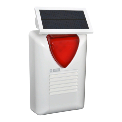
olympia electronics
olympia electronics BS-468/A User manual

olympia electronics
olympia electronics BS-521/1 User manual

olympia electronics
olympia electronics BS-413 User manual

olympia electronics
olympia electronics BS-489 User manual

olympia electronics
olympia electronics BS-458 User manual

olympia electronics
olympia electronics BS-3001 User manual

olympia electronics
olympia electronics BS-475/B User manual

olympia electronics
olympia electronics BSR-5036/A User manual

olympia electronics
olympia electronics ΒS-576/L User manual

olympia electronics
olympia electronics BS-468/A/WL User manual