manuals.online logo
Brands
  1. Home
  2. •
  3. Brands
  4. •
  5. olympia electronics
  6. •
  7. Security System
  8. •
  9. olympia electronics BS-471 User manual

olympia electronics BS-471 User manual

Page 1 of 4
GENERAL
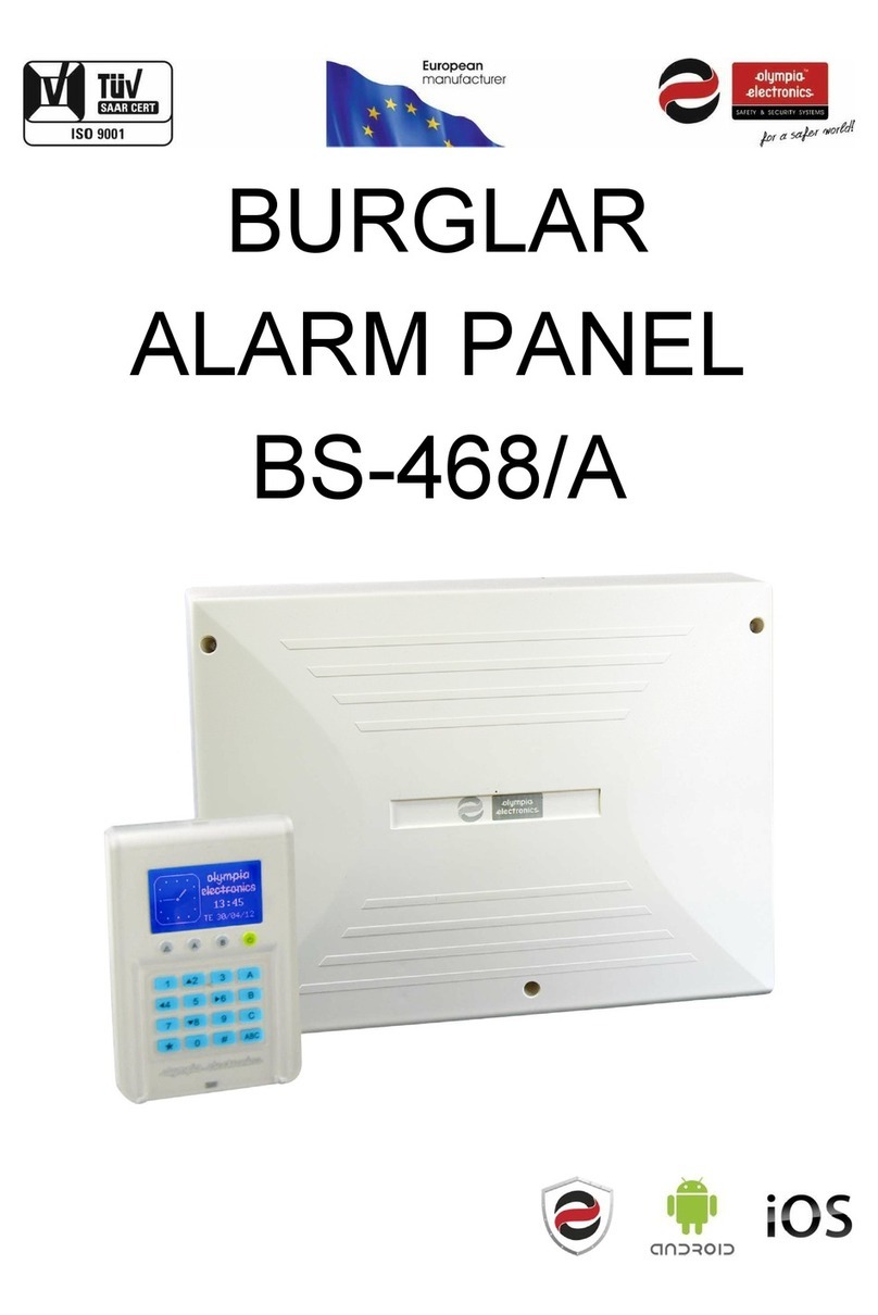
The device BS-471 is a component of the alarm system BS-468/A. It is designed to detect
when a door or a window is opened or closed. It can also accept input from an external
magnetic contact (Normal Close). The detector is powered by battery. It consists of two items,
the electronic device and the magnet.
921471000_09_005
Page 4 of 4 921471000_09_005
Figure 1
External
magnetic
contact
Tamper
hole
Cable
hole
Mounting
holes
Tamper
Switch
Magnet
LED
indicator
Front
device
Plane top view
Plane base layout
The detector checks its battery voltage and transmits the information to the panel.
When the control panel displays a low battery indicator, the detector will continue to
operate for at least 2 weeks. Nevertheless it is recommended to replace the battery
as soon as possible. This must be done by a qualified technician and the control
panel must be in service mode.
I s not allowed to discard batteries in to common trash bins, they must t i
be discarded only in battery recycling points. Do not incinerate.
WARRANTY
WARRANTY
TECHNICAL SPECIFICATIONS
POWER SUPPLY
BATTERY LIFE > 2 Years with 20 activations per day
CR-123A lithium battery (3V rated voltage)
DEGREES OF COVER PROTECTION
PRODUCED IN ACCORDANCE WITH
COMPLY WITH
OPERATION TEMPERATURE RANGE
CONSTRUCTION METERIALS
MAGNET DIMENSIONS (LxWxH)
DEVICE DIMENSIONS (LxWxH)
TYPICAL WEIGHT
GUARANTEE 2 years
ο
-10 to +40 C
FREQUENCY OF COMMUNICATION
COMMUNICATION RANGE
868 MHz
About 200m (open area)
ABS/PC
45 gr.
10 x 15 x 50 mm.
30 x 25 x 106 mm.
EN 50131-1, CLC/TS 50131-2-2, EN 50131-5-3 classification: grade 2
ETSI EN 300220, EN 50130-4, EN 55022, EN 60950-1 ERC REC 70-03
IP40
BATTERY REPLACEMENT
BATTERY REPLACEMENT
Thank you for your trust in our products
Olympia Electronics - European manufacturer
Olympia Electronics guarantees the quality, condition and operation of the goods.
The period of warranty is specified in the official catalogue of Olympia Electronics
and also in the technical leaflet, which accompanies each product. This warranty
ceases to exist if the buyer does not follow the technical instructions included in
official documents given by Olympia Electronics or if the buyer modifies the goods
provided or has any repairs or re-setting done by a third party, unless Olympia
Electronics has fully agreed to them in writing. Products that have been damaged
can be returned to the premises of our company for repair or replacement, as long
as the warranty period is valid.
Olympia Electronics reserves the right to repair or to replace the returned goods and
to or not charge the buyer depending on the reason of defection. Olympia
Electronics reserves the right to charge or not the buyer the transportation cost.
HEAD OFFICE
72nd km. O.N.R. Thessaloniki-Katerini
P.C. 60300 P.O. Box 06 Εginio Pierias Greece
www.olympia-electronics.gr
[email protected]
BS-471 Wireless Magnetic Contact
Magnetic
ON/OFF
Reaction
LITHIUM
3V CR-123A
Delay
Immediate
Page 3 of 4 921471000_09_005
Page 2 of 4 921471000_09_005
MG ON / MG OFF. Disable the internal magnetic sensor. It is useful when the device
co-operates only with external magnetic contacts.
DEL / INS: DEL ensures that there are delays in input and output for installed
detectors at the entrance of a building. The INS allows the detector to directly cause
the triggering of an alarm if the control panel is armed. This DIP-switch (DEL/INS)
has effect only if the scanner has been programmed in a natural reaction from the
control panel (zone with delay or zone without delay).
ATTENTION!! When zone with delay is selected, it is necessary the setting of the
BS-468/A to be done.
The device can be connected to external magnetic contacts via the CN2 terminal
block (Figure 3). If a magnetic field is connected to this input, the device sends an
alarm signal to the control panel. If the contact is not connected to an external
device, at the cable terminal of the CN2, then manufacturer’s cable must remain.
NOTE:The maximum distance of the external sensor cable is 3 meters !!!
Figure 2
Front panel device (side view)
Alignment marks
Installation should only be carried out by qualified technicians. The device is activated when it
is moved away from the magnet. The main device must be installed in the stationary part of
the window or door and the magnet in the moving part. The detector must be installed
vertically. It is forbidden to be installed inside a metal frame (it prevents wireless
communication). Its use is not reliable on an iron door or an iron window.
To install, follow the procedure below:
1. Open the lid of the device.
2. Secure the back plastic to the stationary part of the window or door.
3. Attach the magnet to the moving part. The distance from the device must be a
maximum of 5mm when the door / window is closed. The bottom of the magnet
must be aligned with the bottom of the device (Figure 1). The magnet may be located
either to the left or to the right of the device, but please pay attention to the alignment
marks (Figure 2).
4. Unplug the battery and let the lid open, set the panel to installation mode of wireless
devices (see the manual of the table).
5. Insert the battery into the device and close the lid.
6. Please, note that the device has reverse installation protection for the battery.
CN2
Figure 3.
Example of connection NC external magnetic contacts
with BS-471
Once the device is connected to the panel's network, remove the battery and wait for
10 seconds. Then press the tamper and reinstall the battery. Wait until the LED lights
up. Once you release the tamper, the LED will go out. In this case, the range test will
start. During range test the device LED blinks every second. The duration of range
TEST is 60-95 seconds. When it is finished the LED goes off and after 2 seconds the
test result is displayed as follows:
Single blink: Strong signal. The device can be safely installed at this point.
Two blinks: Normal signal. The device can be safely installed at this point.
Three blinks: Weak signal. It is recommended not to install the device at this point.
There will be communication bettween the device and
the control panel but there will be communication
packets losses.
Four blinks: Out of range. The device is forbidden to be placed in this point.
Note!! As soon as the TEST procedure is started, it is suggested that the device cover
will be placed directly in order to simulate the actual communication conditions. The
environment must be also adapted to the worst possible conditions (eg closed doors).
Finally, in case of home improvements or renovation, it is suggested to perform a
range TEST again.
INSTALLATION
INSTALLATION
DIP SWITCHES
DIP SWITCHES
CONNECTION WITH EXTERNAL MAGNETIC CONTACTS
RANGE TEST
RANGE TEST
Other olympia electronics Security System manuals

olympia electronics BS-413 User manual

olympia electronics

olympia electronics BS-413 User manual

olympia electronics ΒS-576/L User manual

olympia electronics

olympia electronics ΒS-576/L User manual

olympia electronics BS-468/A User manual

olympia electronics

olympia electronics BS-468/A User manual

olympia electronics BS-468/A/WL User manual

olympia electronics

olympia electronics BS-468/A/WL User manual

olympia electronics BS-521/1 User manual

olympia electronics

olympia electronics BS-521/1 User manual

olympia electronics BS-468/A User manual

olympia electronics

olympia electronics BS-468/A User manual

olympia electronics BS-489 User manual

olympia electronics

olympia electronics BS-489 User manual

olympia electronics BS-3001 User manual

olympia electronics

olympia electronics BS-3001 User manual

olympia electronics BS-458 User manual

olympia electronics

olympia electronics BS-458 User manual

olympia electronics ΒSR-5032 User manual

olympia electronics

olympia electronics ΒSR-5032 User manual

olympia electronics BSR-5036/A User manual

olympia electronics

olympia electronics BSR-5036/A User manual

olympia electronics BS-475/B User manual

olympia electronics

olympia electronics BS-475/B User manual

Popular Security System manuals by other brands

Industrial Scientific iAssign Startup guide

Industrial Scientific

Industrial Scientific iAssign Startup guide

ADEMCO Q16 User instruction

ADEMCO

ADEMCO Q16 User instruction

GENESIS INTERNATIONAL SHERLOCK 402 quick start guide

GENESIS INTERNATIONAL

GENESIS INTERNATIONAL SHERLOCK 402 quick start guide

Yacht Devices YDAB-01 user manual

Yacht Devices

Yacht Devices YDAB-01 user manual

ERA VALIANT Installation and operating manual

ERA

ERA VALIANT Installation and operating manual

Intab L-53 user manual

Intab

Intab L-53 user manual

ERA HomeGuard Installation and operating manual

ERA

ERA HomeGuard Installation and operating manual

Cobalt Digital Inc +EAS Manual supplement

Cobalt Digital Inc

Cobalt Digital Inc +EAS Manual supplement

Encore M1 Installation and user manual

Encore

Encore M1 Installation and user manual

Swann DVR4-1100 Specification sheet

Swann

Swann DVR4-1100 Specification sheet

BASETech 1487378 operating instructions

BASETech

BASETech 1487378 operating instructions

Pump Alarm Cellular Alarm Quick start installation guide

Pump Alarm

Pump Alarm Cellular Alarm Quick start installation guide

King Pigeon GSM 3G M2M RTU user manual

King Pigeon

King Pigeon GSM 3G M2M RTU user manual

X10 Orca2000 owner's manual

X10

X10 Orca2000 owner's manual

SpeedTech Lights BOSS S-BDT200 instruction manual

SpeedTech Lights

SpeedTech Lights BOSS S-BDT200 instruction manual

Security Brands S-RTE-S Installation and operation manual

Security Brands

Security Brands S-RTE-S Installation and operation manual

WebEye Wireless webeyeFOG Tech sheet

WebEye

WebEye Wireless webeyeFOG Tech sheet

DAITEM DP8406 manual

DAITEM

DAITEM DP8406 manual

manuals.online logo
manuals.online logoBrands
  • About & Mission
  • Contact us
  • Privacy Policy
  • Terms and Conditions

Copyright 2025 Manuals.Online. All Rights Reserved.