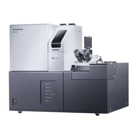
Olympus SLIDEVIEW VS200 User manual

Instructions for use
SLIDEVIEW
VS200
Optical Microscope and Accessory

Any copyrights relating to this manual shall belong to
OlympusSoftImagingSolutionsGmbH.
We at Olympus Soft Imaging Solutions GmbH have tried to make the information contained
in this manual as accurate and reliable as possible. Nevertheless, Olympus Soft Imaging
Solutions GmbH disclaims any warranty of any kind, whether expressed or implied, as to any
matter whatsoever relating to this manual, including without limitation the merchantability
or fitness for any particular purpose. Olympus Soft Imaging Solutions GmbH will from time to
time revise the software described in this manual and reserves the right to make such
changes without obligation to notify the purchaser. In no event shall Olympus Soft Imaging
Solutions GmbH be liable for any indirect, special, incidental, or consequential damages
arising out of purchase or use of this manual or the information contained herein.
No part of this document may be reproduced or transmitted in any form or by any means,
electronic or mechanical for any purpose, without the prior written permission of
OlympusSoftImagingSolutionsGmbH.
All brands are Trademark or registered Trademark of their respective owners.
© Olympus Soft Imaging Solutions GmbH
All rights reserved
Version 510_InstructionsForUse_VS200_de_00_xxJuly2019
Original instructions
Manufactured by
OLYMPUS SOFT IMAGING SOLUTIONS GmbH
Johann-Krane-Weg 39
48149 Münster, Germany
Phone: +49 251 - 798 00 0
Fax: +49 251 - 798 00 6060
Email: info@olympus-sis.com

Contents
1 About this manual 7
1.1 Notes on qualifications 7
1.2 Intended use 7
1.3 Other applicable documents 8
1.4 Symbols in this documentation 8
2 Safety 9
2.1 Categories and symbols in the safety instructions 9
2.2 Caution labels 9
2.3 Caution labels on the product 9
2.4 General safety instructions 10
2.5 Safety instructions for the laser 13
2.6 Safety instructions for X-Cite Turbo and X-Cite Xylis 13
3 Hinweise zum Aufstellen 14
3.1 Betriebs- und Lagerbedingungen 14
4 Tools and accessories 16
5 Scope of supply 17
6 System diagram 20
6.1 Available fluorescence components 20
7 Trays 22
7.1 Tray description 22
7.2 VS200 Tray types 22
8 Specifications 24
9 Unboxing 26
9.1 VS200 Scanner 26
9.1.1 Mounting of handles - VS200 scanner 26
9.2 Transportation locks for the VS200 scanner 26
9.2.1 Removing transportation lock from stage 27
9.2.2 Removing transportation lock from transmitted light condenser
(BX3-UCD8A) 28
9.3 VS200 Loader 30
9.3.1 VS200 Trays 32
9.3.2 PC and monitor 32
9.4 VS200 loader transportation locks 32
9.4.1 Removing transportation lock from VS200 loader’s tray hotel 33
9.4.2 Removing transportation lock from SCARA robot arm 34
- 3 - Instructions for useOLYMPUS VS200 System

9.4.3 Removing transportation lock from SCARA robot arm’s coun-
terweight 35
10 Mounting of components 37
10.1 Scanner 37
10.1.1 Objectives 37
10.1.2 Immersion Objectives 38
10.1.3 Phase Contrast (PH) objectives 39
11 Mounting fluorescence components 40
11.1 IX3-RFACA and IX3-RFALFE 40
11.2 Fluorescence filter wheels or camera adapter for monochrome camera 45
11.2.1 U-FFWR (Motorized fast reflected light filter wheel) 45
11.2.2 Add or replace filter (U-FFWR) 47
11.2.3 U-FFWO T3 (Motorized fast observation filter wheel) 49
11.2.4 Add or replace filter (U-FFWO) 51
11.2.5 TV 1.0x adapter 52
11.3 Monochrome camera 52
11.3.1 Orientation of the monochrome camera 53
11.4 X-Cite adapter 56
11.5 4x Objective 57
11.6 LED light source 57
11.7 Filter set 58
11.7.1 U-FF filter cube (IX3) 58
11.7.2 Add or replace filter cube (IX3) 59
11.7.3 U-FDICT filter cube 60
11.7.4 X-Cite Turbo 61
12 Assembly of the housing for scanner 62
12.1 Left panel 62
12.2 Right Panel 64
12.3 Back panel 65
12.4 Top panel 66
13 Cabling 70
14 Assembly of the loader housing 72
14.1 Top panel 72
14.2 Back panel 72
14.3 Front panels 73
15 Verbindung VS200 Scanner und VS200 Loader 75
15.1 Mechanical Connection VS200 scanner and VS200 loader 75
- 4 - Instructions for useOLYMPUS VS200 System

16 PC operating system language 77
17 VS200 ASW software setup 78
18 VS200 device configuration 85
18.1 Activate the motorized polarizer 86
18.2 Activate the VS200 liquid dispenser 86
18.3 Device settings - objectives 87
18.4 Device settings - filter 88
18.5 Manual device configuration 89
18.5.1 ORCA monochrome camera 90
18.6 Device customization 90
18.6.1 ORCA camera adjustments 91
18.6.2 Setup phase contrast (PH) observation method 92
18.6.3 Setup polarization (Pol) observation method 94
18.6.4 Create or adjust an observation method 95
18.7 VS200 LED lamp voltages 97
18.7.1 Orca Flash 4.0 voltages (%) 97
18.7.2 Orca Fusion voltages (%) 97
18.7.3 VS-304M voltages (%) 98
18.7.4 VS-264C voltages (%) 98
19 How to insert a slide into a tray 99
19.1 How to insert a tray into the VS200 scanner 99
19.2 Insert a tray into the VS200 loader 100
20 Calibrate VS200 using the Olympus Calibration Slide 101
20.1 Stage limits - Z Axis 103
20.2 Camera adapter calibration for iDS (VS-264C) camera 106
20.3 Camera-To-Stage Rotation 110
20.4 XY Objective Shift / Parfocality 112
20.5 Shading Correction (Brightfield) 115
20.6 Shading correction of the label area 123
20.6.1 Preparation of calibration slide 123
20.6.2 Shading correction for polarization (Pol) 131
20.7 Magnification Test Scan 136
21 Additional calibrations for a fluorescence system 138
21.1 Camera adapter 139
21.1.1 Camera adapter U-FFWO T3 139
21.2 Camera-To-Stage Rotation 144
21.3 Camera shift 146
- 5 - Instructions for useOLYMPUS VS200 System

21.4 Lens Correction 150
21.5 Shading correction BFMono 153
21.6 Magnification Test Scan 158
21.7 Shading correction for fluorescence observation methods 160
21.8 Shading correction for darkfield (DFMono) 164
21.9 Shading correction for PhaseContrast (PH) 167
21.10 Channel-XY-Shift 171
22 Cleaning the system 174
22.1 Cleaning the scanner 174
22.2 Cleaning the loader 174
22.3 Cleaning the trays 175
22.4 Cleaning the X-Cite Turbo 175
22.5 Cleaning the immersion objective 175
23 Additional software installation 178
23.1 OlyVIA 178
23.2 VS200 ASW Desktop 178
23.3 NetImage Server SQL (NIS-SQL) and Webinterface 178
24 Troubleshooting 179
24.1 Hardware not available 179
24.2 "No camera" error 179
24.3 Tray not active 179
24.4 Image too bright 180
24.5 Setting the Koehler illumination 180
25 Proper selection of the power supply cord 186
26 Declarations of conformity and disposal 189
26.1 CE Conformity (Europe) 189
26.2 WEEE declaration (Europe) 189
26.3 RoHS Conformity (Europe) 189
26.4 FCC conformity (USA) 189
26.5 For Korea only 190
26.6 China RoHS conformity (China) 190
26.7 RFID 190
26.7.1 RFID (Korea) 190
26.7.2 RFID (USA) 190
26.7.3 RFID (Canada) 191
26.7.4 RFID (Taiwan) 191
27 Support 192
- 6 - Instructions for useOLYMPUS VS200 System

1 About this manual
1 About this manual
This manual for the VS200 system is for Olympus technicians as well as users of the
VS200 system who have been trained by Olympus. The manual contains important
information on how to operate the VS200 system safely and correctly.
In addition, this manual describes how to unbox and install the system as well as
how to install further components. These tasks must expressly only be performed by
Olympus. As a user you are not allowed to unbox or install the VS200 system by your-
self!
To ensure the safety, obtain optimum performance and to familiarize yourself fully
with the use of this product, study this manual thoroughly before installing this
product, and always keep this manual at hand when operating this product.
Retain this instruction manual in an easily accessible place near the work area for
future reference.
Installing and configuring a liquid dispenser, and upgrading to a VS200
loader are not in the scope of this document. These must only be installed
and adjusted by technical service of Olympus.
1.1 Notes on qualifications
Olympus personnel Instructions for tasks that must only be performed by Olympus
are identified with the following note:
The units described below must be assembled and adjus-
ted by Olympus. If these units are assembled or adjusted
by the customer, the operations are not ensured.
1.2 Intended use
The system is intended to be used for the acquisition of virtual slide images. The sys-
tem is intended to be used for research only.
If the VS200 system is used in a manner not specified by this manual, the safety of
the user may be at risk. In addition, the VS200 system may also be damaged. Always
use the VS200 system according to this instruction manual.
Olympus Soft Imaging Solutions GmbH takes no responsibility for damaged caused
by unintended use.
Foreseeable misuse
The system is not intended to be used for primary diagnosis.
- 7 - Instructions for useOLYMPUS VS200 System

1.3 Other applicable documents
Familiarize yourself with all of the other manuals for the components of the system.
Take special note of the safety instructions they contain.
1.4 Symbols in this documentation
Tools required for performing the steps
Preconditions for the subsequent steps
- 8 - Instructions for use
1 About this manual
OLYMPUS VS200 System

2 Safety
2 Safety
If the product is used in a manner not specified by this manual, the safety of the user
may be imperiled. In addition, the product may also be damaged. Always use the
product as outlined in this instruction manual.
2.1 Categories and symbols in the safety instructions
The safety instructions in this manual use symbols and keywords that are divided
into the following categories:
CAUTION
This warning sign and the word CAUTION indicate dangerous situations that
can lead to minor injury if ignored.
ATTENTION
The exclamation mark and the word ATTENTION indicate situations where irre-
parable damage to the product can occur if ignored.
Useful tips and important information
This symbol indicates useful notes, tips and important information.
2.2 Caution labels
Indicates a non-specific general hazard.
This warning sign indicates that there is a crush hazard.
2.3 Caution labels on the product
Caution labels have been placed at positions where special care is required when
handling and operating the system. Always pay attention to the caution labels.
CAUTION
Moving components can cause injury
Im Inneren des VS200 Systems verfahren Komponenten. Gaps open and close.
Hands and fingers can get crushed.
Sobald das System mit der Stromversorgung verbunden ist, Haare, Finger,
Hände und andere Körperteile sowie Kleidung und Gegenstände aus dem
Inneren des VS200 Systems fernhalten.
- 9 - Instructions for useOLYMPUS VS200 System

Position of caution labels
U-FFWO
Loader
Im Bereich des Mikroskoptisches
Nosepiece
Flap door
Flap door motor
2.4 General safety instructions
Do not plug anything into or unplug anything from the ports when the system is
connected to the power supply.
The system is not intended to be used for general microscopy tasks.
No guarantee is provided on an image file. For example, even if the following
state is generated attributable to an operation error of an observer, malfunction
of the device, a system failure including a potential one, or the like, or at the time
of normal operation or normal movement, it will not be possible to perform
image restoration or damage compensation.
1. Abnormal state of an image
2. Abnormal state of file property such as a file name and file date and time
3. Disappearance of an image
Confirm, edit or save the image for backup through care of the observer. To be
noted is that the electronic recording media such as USB memory, HDD and
DVD-R have retention lives in general and there may be the case that a file saved
may disappear in several years.
Further, there is no authenticity or tamper-proof characteristic.
Prevent from strong vibrations as they can impair the image quality.
Regarding to 3-axes control unit for scanning stages and motorised focus drives,
1. Item caution for use
2. Installation prevent from strong vibrations and risk of explosion
3. Temperature prevent from direct sunlight or strong heat sources
4. Humidity prevent from splash water and moisture
- 10 - Instructions for use
2 Safety
OLYMPUS VS200 System

2 Safety
5. Radiation prevent from magnetic or electromagnetic sources in close
proximity. Prevent from radioactive contamination
6. Chemicals/ toxic substances prevent from substances that are corrosive,
potentially infectious, toxic or otherwise hazardous to health
Regarding Monitor
1. Do not use this product near water.
2. Do not place this product on an unstable cart, stand or table. If the
product falls, it could be seriously damaged.
3. Slots and openings are provided for ventilation to ensure reliable oper-
ation of the product and to protect it from overheating. These openings
must not be blocked or covered. The openings should never be blocked
by placing the product on a bed, sofa, rug or other similar surface. This
product should never be placed near or over a radiator or heat register,
or in a built-in installation unless proper ventilation is provided.
4. Never push objects of any kind into this product through cabinet slots
as they may touch dangerous voltage points or short-out parts that
could result in a fire or electric shock. Never spill liquid of any kind onto
or into the product.
The system must not be used for primary diagnosis.
Possible data loss or invalid hardware states when forcing application to shut-
down. The application has no means of resisting a "forced shutdown" (e.g. due
to a forced "Windows Update" or application kill via the "Task Manager", power
loss, or a computer reboot). The user is generally required to not initiate such a
forced shutdown. If the application is forced to shut down without being prop-
erly closed anyway, the following problems may occur:
The system may not be able to save and restore the current status of the
application (including any non-saved states / images / settings).
It may be necessary for a service technician to check the system to make it
operational again.
Photobleaching possible
The system has a fluorescence light source with high light intensity. Pho-
tosensitive samples might be photo-bleached if they exposed to high-intensity
light for long times (e.g. 60s). This can happen when the sample is being
viewed in live mode or if it is scanned repeatedly (e.g. 10 times) on the specimen
sites that are auto-focused a lot of times. The photobleaching is often only faint
and only visible if the 16bit display limits are set very narrow. In order to prevent
this, it can be useful to create alternative observation methods with reduced
light intensity in order to only use as much light as necessary and avoid "over-
loading" the sample with excitation light.
- 11 - Instructions for useOLYMPUS VS200 System

Shading / unneven light intensity
For specimens with very sparse samples with a lot of empty background and
rather small fluorescence emittance(e.g. FISH samples), it can occur that images
acquired with Fluorescence illumination show a variance in background illu-
mination ("shading").
If the product is being used in a network environment, note the following
points.
Make sure that the network has appropriate virus protection.
The installation of operating system service packs, security patches or third
party software updates (including runtime libraries) can cause malfunctions.
If anti-virus software is running while you are acquiring images, it can lead to
the loss of individual acquisitions.It can also slow down the acquisition pro-
cess or even cause it to be aborted altogether.
- 12 - Instructions for use
2 Safety
OLYMPUS VS200 System

2 Safety
2.5 Safety instructions for the laser
1. The loader uses a laser sensor. Never remove the warning and caution
labels on the product. The semiconductor laser for loader incorporated in
this product it designated as a product of the following class.
CLASS 1 LASER PRODUCT(IEC60825-1:2007 / IEC608251:2014)
This product complies with 21 CFR 1040. 10 and 1040. 11 except for
deviations pursuant to Laser Notice No. 56, dated June 24, 2007.
2. Never attempt to remove the cover using a tool. There is a risk of exposure
to the internal strong laser beam as well as other malfunction or failure.
3. Do not look into the light source either directly or indirectly. Otherwise, eye
inquires may occur.
2.6 Safety instructions for X-Cite Turbo and X-Cite Xylis
The X-Cite Turbo light source is not available in all countries.
Follow the safety precautions at all times during operation and maintenance of this
product. Non-observance may result in eye injury or damage to the system.
CAUTION
Risk of injury to the eyes
Do not look at operating lamp/LED as it can emit UV light.
Never look into the light emitting end of the light guide. The light could
severely damage the eye if the light is observed directly.
Always make sure the liquid light guide and X-Cite adapter are securely attached
to the VS200 system. This will minimize the risk of exposure to the UV light.
If the light source has a malfunction please contact Olympus or Excelitas cus-
tomer support. If the light source is serviced always make sure that the power
cord is disconnected.
Place the unit onto a hard, stable surface and make sure the ventilation openings
are not covered by something.
- 13 - Instructions for useOLYMPUS VS200 System

3 Hinweise zum Aufstellen
A fully equipped VS200 system weighs approx. 190kg. Consider this weight
when selecting the work surface. Beachten Sie die Angaben zum Gewicht, wenn
Sie das VS200 System bzw. die Komponenten anheben. See Specifications auf
Seite 24.
Die Aufstellfläche mussfür eine Tragfähigkeit von mindestens 190kg ausgelegt
sein.
Place the VS200 system on a sturdy level table or bench, taking care not to block
the ventilation slots of the scanner and loader.
When setting up the VS200 system, ensure that there is a minimum distance of
30cm from the wall and 20cm from other devices.
The devices must only be moved using the designated handles to avoid dam-
ages on the device and personal injuries.
The system should not be repositioned by the end user. If the system has to be
repositioned an Olympus sales representative has to be contacted first.
3.1 Betriebs- und Lagerbedingungen
Positioning the system Only use the system indoors and in a laboratory or laboratory-
like environment
Elevation 2000m maximum
Ambient temperature The maximum permissible range for the ambient temperature
during operation of the VS200 system is 12 to 28°C.
Humidity The maximum permissible humidity during operation of the
VS200 system is 80% for temperatures up to 31°C (88°F, con-
densation free) decreasing linearly through 70% at 34°C (93°F)
and 60% at 37°C (99°F).
Power supply voltage fluc-
tuation
The power supply should not fluctuate by more than 10% of the
nominal voltage.
Pollution degree 2 (in accordance with IEC60664)
Installation category (over-
voltage category)
II (in accordance with IEC60664)
Space required for the system
VS200 System without loader
Without fluorescence With fluorescence
Height 530mm 885mm
Area of work surface (table) 1500mm x 800mm 1500mm x 800mm
- 14 - Instructions for use
3 Hinweise zum Aufstellen
OLYMPUS VS200 System

3 Hinweise zum Aufstellen
VS200 System with loader
Without fluorescence With fluorescence
Height 885mm 885mm
Area of work surface (table) 1800mm x 800mm 1800mm x 800mm
Storage conditions
The maximum permissible range for the ambient temperature for storage of the VS200 system is
-25 to 55°C.
The maximum permissible relative humidity range for storage is 10% to 95%.
The maximum permissible temperature change rate for storage is 30°C/h.
The maximum permissible atmospheric pressure for storage is 70 to 106 kPa.
- 15 - Instructions for useOLYMPUS VS200 System

4 Tools and accessories
2,5mm, 3mm with ball end, 4mm, 5mm hex keys
- 16 - Instructions for use
4 Tools and accessories
OLYMPUS VS200 System

5 Scope of supply
5 Scope of supply
VS200 Single Tray and VS200 Multi Tray Loader
1st pallet VS200 base unit
2nd pallet Housing panel left
Housing panel right (different variant for single tray and multi
tray loader)
Housing panel back
Housing back panel cover
Housing panel top front
Housing panel top back
Housing beam splitter cover
4 handles to carry the system
PLN2x
UPLANXAPO20x
1 1x3 inch tray
VS200 standard computer with mouse and keyboard
HP TFT 27 inch
Instruction manual
Calibration slide v2.0
Additional box Power supply (not available in all countries)
Optional hardware
VS200 loader
Pallet VS200 loader
Housing panel back
Housing panel top
Housing back panel cover
4 1x4 inch tray
Instruction manual
- 17 - Instructions for useOLYMPUS VS200 System

Fluorescence kit A
Box IX3-RFACA
IX3-RFALFE
UPFLN4x
U-FF filter cube
TV1XC
U-FFWR
X-Cite Xylis
Fluorescence kit B
Box IX3-RFACA
IX3-RFALFE
UPFLN4x
U-FF filter cube
2x Black-out filter
1x Glas filter
U-FFWO T3
U-FFWR
X-Cite Xylis
Fluorescence kit C
The Fluorescence kit C is not available in all countries.
Box IX3-RFACA
IX3-RFALFE
UPFLN4x
U-FF filter cube
2x Black-out filter
1x Glas filter
U-FFWO T3
X-Cite Turbo
Fluorescence kit D
The Fluorescence kit D is not available in all countries.
- 18 - Instructions for use
5 Scope of supply
OLYMPUS VS200 System

5 Scope of supply
Box IX3-RFACA
IX3-RFALFE
UPFLN4x
U-FF filter cube
TV1XC
X-Cite Turbo
- 19 - Instructions for useOLYMPUS VS200 System

6 System diagram
1 2
4
3
5
6
7
9
VS20-BU
VS200 Slide Scanner Base Unit for Single Tray Loading
8
5
VS20-POWSUP
VS200 Power Supply
4
VS20-LIQDIS
Oil dispenser System
3
VS20-CAM-COVER
VS200 Intermediate Part
to Cover the B/W Camera
7
VS20-BU-L
VS200 Slide Scanner
Base Unit for Loader
8
VS20-LOADER
VS200 Slide Loader Unit
10
VS20-LOAD-UG
VS200 Slide Loader
Upgrade for Single Tray
Loading Units
10
2
VS20-304M
FL camera VS304M
HAMAMATSU C13440-
20CU
Hamamatsu Orca Flash 4.0
V3
Hamamatsu Orca Fusion
1
VS20-FL-A
Fluorescence excitation
lter wheel and white light
LED
VS20-FL-B
Fluorescence excitation and
emission lter wheels and
white light LED
VS20-FL-C
Fluorescence emission lter
wheels and switchable LED
VS20-FL-D
Fluorescence with
switchable LED only
6
VS20-ST13
VS200 SlideTray
(1”x 3”)
VS20-ST13X5
VS200 SlideTray
(set of 5 trays for
1”x3” slides)
VS20-ST23
VS200 SlideTray
(2”x3”)
VS20-ST34
VS200 SlideTray
(3”x4”)
VS20-ST45
VS200 SlideTray
(4”x5”)
7
Fluorescence Cameras
Fluorescence Solution
Additional Tray Solutions
Additional Objective Solutions
VS200 system diagram
Loader Options
Standard Setup Single Tray Loading Unit
Front view Rear view
XAPO/SAPO Objective
10X UPLXAPO10X
40X UPLXAPO40X
40X UPLXAPO40XO
60X UPLXAPO60XO
60X UPLSAPO60XS
100X UPLXAPO100XO
100X UPLSAPO100XS
PH Objective
4X UPLFLN 4XPH
10X UPLFLN 10X2PH
20X UPLFLN 20XPH
40X UPLFLN 40XPH
60X UPLFLN 60XOIPH
100X UPLFLN 100XO2PH
6.1 Available fluorescence components
The VS200 system can be ordered with four different fluorescence sets. Each set con-
tains a basic configuration plus individual components. Filter sets and cameras are
not part of the configuration.
Remark: Configuration C and D are not available in all countries.
Basic configuration
Component A B C D
IX3-RFACA X X X X
IX3-RFALFE X X X X
UPFLN4X object-
ive
XXXX
U-FF, filter cube
(empty)
XXXX
Individual components
- 20 - Instructions for use
6 System diagram
OLYMPUS VS200 System
Table of contents
Other Olympus Microscope manuals

Olympus
Olympus CK30 User manual

Olympus
Olympus BH2 Series Installation instructions

Olympus
Olympus JM User manual

Olympus
Olympus SZ-III User manual
Olympus
Olympus U-D5BDREMC-VA3 Operating instructions

Olympus
Olympus BX-URA2 User manual

Olympus
Olympus DP71 User manual

Olympus
Olympus FH User manual

Olympus
Olympus VM Series User manual

Olympus
Olympus KHC User manual

Olympus
Olympus CHBS User manual

Olympus
Olympus CHA-P User manual

Olympus
Olympus BHTU User manual

Olympus
Olympus BX53M User manual

Olympus
Olympus DSX1000 User manual

Olympus
Olympus DSX1000 User manual

Olympus
Olympus 1X71 User manual

Olympus
Olympus SZX16 User manual

Olympus
Olympus BX60M User manual

Olympus
Olympus BX3-SSU User manual