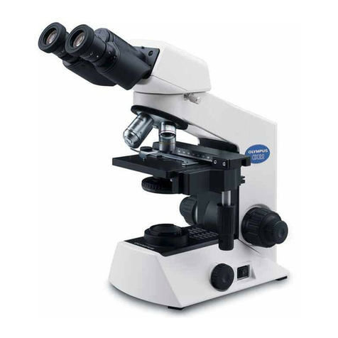
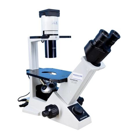
Olympus CKX53 User manual

Instructions
Notes
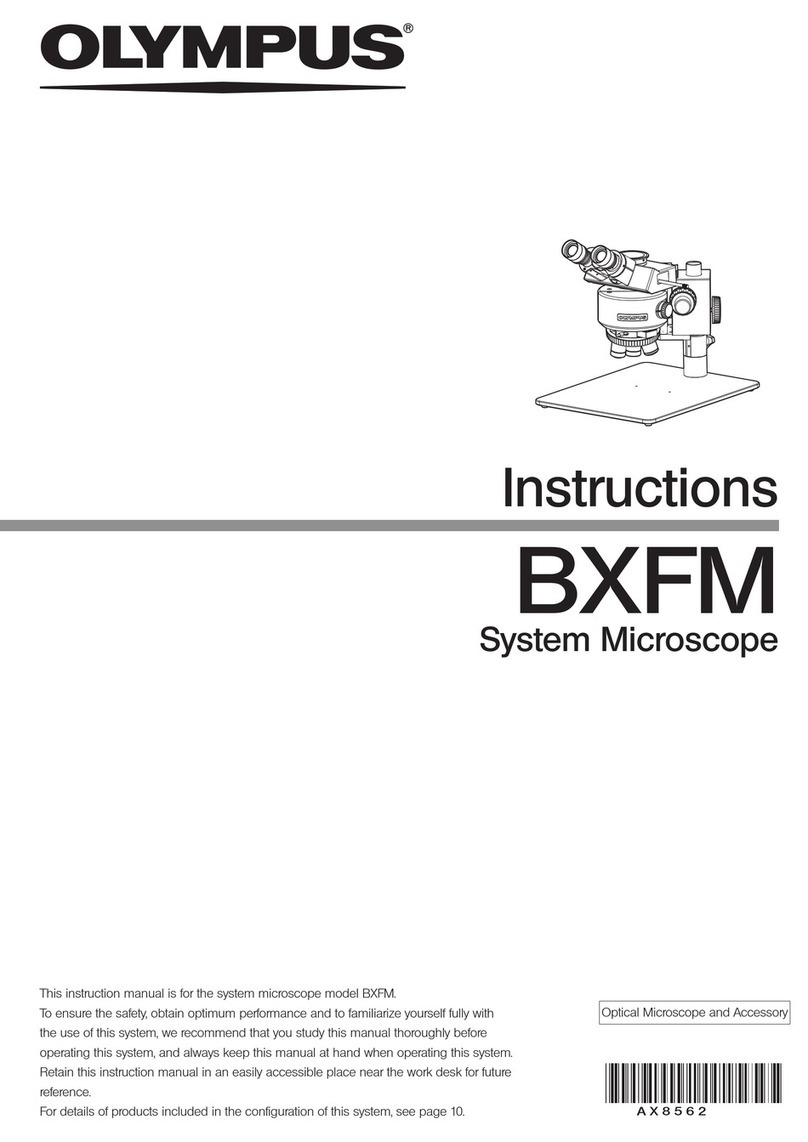
This instruction manual is for the Olympus culture microscope model CKX53.
To ensure the safety, obtain optimum performance and to familiarize yourself fully with the use of the
microscope, we recommend that you study this manual thoroughly before operating the microscope,
and always keep this manual at hand when operating the microscope.
Retain this instruction manual in an easily accessible place near the work desk for future reference.
For details of products included in the configuration of this system, see page 7.
CKX53
A X 8 6 6 0
Culture Microscope
Optical microscope and accessory

In accordance with European Directive on Waste Electrical and Electronic Equipment, this
symbol indicates that the product must not be disposed of as unsorted municipal waste, but
should be collected separately.
Refer to your local Olympus distributor in EU for return and/or collection systems available in
your country.
NOTE: This product has been tested and found to comply with the limits for a Class A digital device,
pursuant to Part 15 of the FCC Rules. These limits are designed to provide reasonable protection
against harmful interference when the product is operated in a commercial environment. This product
generates, uses, and can radiate radio frequency energy and, if not installed and used in accordance
with the instruction manual, may cause harmful interference to radio communications.
Operation of this product in a residential area is likely to cause harmful interference in which case the
user will be required to correct the interference at his own expense.
FCC WARNING: Changes or modifications not expressly approved by the party responsible for compliance
could void the user’s authority to operate the product.
For Korea only
B급 기기 (가정용 방송통신기자재)
이 기기는 가정용(B급) 전자파적합기기로서 주로 가정에서 사용하는 것을
목적으로 하며, 모든 지역에서 사용할 수 있습니다.

Introduction....................................................................................................................................................... 1
Safety precautions...................................................................................................................................... 2
1 Nomenclature of units........................................................................................................................ 7
2 Nomenclature of main operating portions....................................................................... 8
2-1 Bright field set / Phase contrast entry set / Phase contrast standard set..... 8
2-2 Fluorescence set............................................................................................................................................... 9
3 Observation procedures.................................................................................................................10
3-1 Preparation of observation .....................................................................................................................10
1Moving the microscope........................................................................................................................................................10
2Attaching AC adapter and power cord................................................................................................................. 10
3Cleaning and sterilizing around the stage.......................................................................................................... 11
3-2 Procedures to place specimens.......................................................................................................11
1Placing the container on the stage............................................................................................................................ 11
2When using the optional stage unit.......................................................................................................................... 11
3When using the high container (Procedures to attach / detach the condenser portion)........................12
3-3 Observation methods (Bright field observation / Phase contrast observation)............12
1Turning ON the light source (LED)............................................................................................................................... 12
2Changing between bright field observation and phase contrast observation
(Phase contrast entry set / Phase contrast standard set / Fluorescence set)................... 12
3Adjusting the aperture iris diaphragm..................................................................................................................... 13
4Selecting the objective.......................................................................................................................................................... 13
5Changing between the visual light path and the camera light path........................................... 13
6Focusing on the specimen................................................................................................................................................ 14
7Adjusting the brightness...................................................................................................................................................... 14
8Moving the specimen ........................................................................................................................................................... 14
Contents

3-4 Observation method (Fluorescence observation)..............................................................15
1Inserting the shutter for reflected light illumination (Fluorescence set)....................................15
2Inserting the umbra shield (ambient light shielding plate) (Fluorescence set)...................15
3Turning ON the light source (mercury burner) (Fluorescence set)................................................. 15
4Inserting the fluorescence mirror unit (Fluorescence set)..................................................................... 16
5Changing between the visual light path and the camera light path...........................................16
6Selecting the objective..........................................................................................................................................................16
7Opening the shutter for reflected light illumination (Fluorescence set).................................16
8Focusing on the specimen................................................................................................................................................16
9Moving the specimen............................................................................................................................................................. 16
3-5 Recording with the camera....................................................................................................................17
1Changing between the visual light path and the camera light path........................................... 17
2Focusing on the specimen................................................................................................................................................ 17
3Acquiring the image ................................................................................................................................................................ 17
3-6 Cleaning up..........................................................................................................................................................18
1Cleaning up the fluorescence illuminator (Fluorescence set)...........................................................18
2Turning OFF the light source (mercury burner) (Fluorescence set)............................................... 18
3Turning OFF the light source (LED)
(Bright field set / Phase contrast entry set / Phase contrast standard set)..........................18
4Removing the AC adapter and the power cord .............................................................................................18
5Cleaning up the microscope...........................................................................................................................................18
4 For advanced observation ..........................................................................................................19
4-1 Adjusting the binocular portion..........................................................................................................19
1Adjusting the interpupillary distance........................................................................................................................ 19
2Adjusting the diopter...............................................................................................................................................................19
3Using the eye shades............................................................................................................................................................19

4-2 Adjusting the tension of the coarse focusing knob........................................................20
4-3 Operating procedures of the transmitted light illumination filter (option)....20
4-4 Adjusting the umbra shield (ambient light shielding plate) position
(Fluorescence set)..........................................................................................................................................20
4-5 Adjusting the field iris diaphragm in fluorescence observation (Fluorescence set).... 21
4-6 Observing with the objective with correction collar (option)................................... 21
4-7 Centering of the centering phase contrast sider IX2-SL (option) .......................22
4-8 Operating procedures of PLN2X and CKX3-SLPAS (option)....................................22
4-9 Operating procedures of CKX3-SLPIC (option)...................................................................23
4-10 Selecting procedures of the specimen holder (option) ............................................ 23
4-11 Selecting procedures of the fluorescence mirror unit (including options)...24
1Selecting the fluorescence mirror unit (Fluorescence set)...................................................................24
2Spectral characteristics of the filter of the fluorescence mirror unit (Fluorescence set) ........24
5 Troubleshooting....................................................................................................................................25
5-1 Bright field observation / Phase contrast observation .................................................25
5-2 Fluorescence observation...................................................................................................................... 26
5-3 Common in all observation methods...........................................................................................27
6 Specifications..........................................................................................................................................28
6-1 Sets with CKX53.............................................................................................................................................28
6-2 Objective................................................................................................................................................................30
6-3 Optional units ....................................................................................................................................................30
6-4 Operating environment............................................................................................................................. 31
7 Assembly ...................................................................................................................................................32
7-1 Assembly diagram.........................................................................................................................................32
7-2 Assembly of the microscope frame CKX53SF.....................................................................33

7-3 Assembly of the fluorescence illuminator CKX3-RFA (Fluorescence set) .......34
7-4 Assembling the stage (Phase contrast standard set / Fluorescence set)......38
7-5 Attaching the objectives...........................................................................................................................39
7-6 Attaching the phase contrast slider
(Phase contrast entry set / Phase contrast standard set).......................................... 40
7-7 Attaching the filter slider for transmitted light illumination ........................................ 41
7-8 Attaching the light source for reflected light illumination (Fluorescence set)........ 41
7-9 Attaching the camera..................................................................................................................................45
8 Preventive inspection sheet for illumination devices
(Fluorescence set) .............................................................................................................................46
9 Appendix..................................................................................................................................................... 47
9-1 Summary of procedures of bright field observation / phase contrast observation....... 47
9-2 Summary of fluorescence observation procedures........................................................ 48

1
CKX53
Configuration of instruction manuals
Read all the instruction manuals supplied with the units you purchased.
The following instruction manuals are prepared for this product.
Instruction manuals Main contents
CKX53 (this document) Operation procedures of the microscope, etc.
Mercury power supply unit
U-RFL-T Power supply unit of mercury lamp housing
Light guide illumination system
U-HGLGPS Light guide illumination system
Introduction
Intended use
This product has been designed to be used to observe magnified images of specimens in various routine work and
research applications.
This includes the observation of living cells or of specimen taken from tissues to gain physiological or morphological
information at hospitals or laboratories. Typical field of applications are genetics, human blood and tissue examination,
neurology, pharmacology and cellular biology.
Do not use this instrument for any purpose other than its intended use.
This product complies with the requirements of directive 98/79/EC concerning in vitro
diagnostic medical devices. CE marking means the conformity to the directive.
This product is applied with the requirements of EMC standard IEC/EN61326-2-6 and
IEC/EN61326-1 concerning electromagnetic compatibility.
This product complies with the emission and immunity requirements described in IEC61326
series. The electromagnetic environment should be evaluated prior to operation of this product.

2
If the product is used in a manner not specified by this manual, the safety of the user may be imperiled. In addition, the
product may also be damaged. Always use this product according to the instruction manual.
The following symbols are used in this instruction manual.
CAUTION : Indicates a potentially hazardous situation which, if not avoided, may result in
minor or moderate injury.
NOTE
: Indicates a potentially hazardous situation which, if not avoided, may result in
damage to the product or other property.
TIP
: Indicates the useful knowledge or information for use.
CAUTION - Prevention of infection -
CAUTION - Installation of the product -
If you observe specimens which have potentiality of infection, please comply with following items to
prevent from infection.
• Wear protective equipment such as gloves, etc.
Wear protective equipment such as gloves, etc. to prevent the specimens from touching your skin directly.
When you maintain the product which may have contacted the specimens, wear protective equipment such as
gloves, etc., or clean the product before operation.
• Follow the procedures described in chapter "Handling Precautions ".
Follow the procedures described in chapter "Handling Precautions" (page 5) prior to using the units of this product.
Otherwise, the stability of this product will be lost and the dropped sample will cause the possibility of infection.
• After observation, clean the portions where specimens contacted directly.
• Remove the specimen when moving the product.
When moving this product, be sure to remove the specimen first, since it is in danger of dropping and spattering.
• In case the specimen is damaged, promptly take the infection prevention measures.
• When disposing of the product, follow the regulations and rules of your local government.
When disposing of the product which contacted the specimens, be sure to follow the regulations and rules of your
local government.
• Follow the laboratory biosafety guidelines issued by WHO.
In addition, refer to the laboratory biosafety guidelines issued by WHO. This microscope is assumed to be used with
the biosafety level 3 or lower.
Install this product on a sturdy, level table or bench.
For safety in particular, do not place a mat, etc. under the product.
Safety precautions

3
CKX53
CAUTION - Illumination light (LED illumination light) for bright field
observation / phase contrast observation -
CAUTION - Electric safety -
Always use the AC adapter, the power cord and other cables provided by Olympus.
If other AC adapters, power cords, or cables are used, the electric safety and the EMC (Electro-Magnetic Compatibility)
performance of the product can not be assured. If no power cord is provided, please select the proper power cord by
referring to the section “Proper selection of the power cord” at the end of this instruction manual.
Always connect the ground terminal.
Connect the ground terminal of the power cord and that of the power outlet. If the product is not grounded, our
intended electric safety and EMC performance of the product can not be assured.
Do not use the product in close proximity to the sources of strong electromagnetic radiation.
Proper operation may be interfered. The electromagnetic environment should be evaluated prior to operation of the
product.
Do not touch the AC adapter, the power cord, or other cables or switches with wet hands.
If you touch them with wet hands, you may get an electric shock.
Remove the power cord in case of emergency.
In case of emergency, remove the power cord from the power cord connector on the product or from the power outlet.
Install the product at a location where you can reach the power cord connector or the power outlet at hand to remove
the power cord quickly.
This product complies with the emission and immunity requirements described in IEC61326 series.
CAUTION - Illumination light for fluorescence observation -
Do not look directly at the light coming out from the objective and the reflected light from the
specimen.
Attach the cap to the screw hole of the revolving nosepiece where the objective is not attached.
Engage the umbra shield (ambient light shielding plate) (see page 9) in the light path.
Be careful about the light emitted during the fluorescence observation, since not only visible light but also light of
invisible wavelengths (such as ultraviolet and infrared) may be emitted depending on the illumination methods.
Do not expose your skin to the light coming out from the objective for a long time.
Do not expose your skin to the light, since you may get burned.
Do not allow flammable gas or liquid to get close to the light coming out from the objective.
Do not allow flammable gas or liquid to get close to the light, since it may cause fire.
Do not look directly at the light from LED for a long time.
This product uses LED as a light source for the bright field observation and the phase contrast observation. This LED
is basically eye-safe. However, do not look directly at the light from LED for a long time, since it may cause damage to
your eyes.
4
The following symbols are placed on this product.
Study the meaning of the symbols and always use the product in the safest possible manner.
Symbol Meaning
Indicates high voltage (1kV or more). Take special care to prevent electric shock.
Indicates that the surface becomes hot, and should not be touched with bare hands.
It may cause burns.
Indicates a non-specific general hazard. Follow the description given after this symbol
or in the instruction manual.
Indicates the main switch of push button type.
(Push button type is the the type of switch that ON or OFF is selected each time it is pressed.)
Indicates that the seesaw type main switch is ON.
(Seesaw type is the type of switch that ON or OFF is selected by pressing it to ON or OFF side.)
Indicates that the seesaw type main switch is OFF.
Caution labels
The cautions are displayed on the portions which require special cautions during use and operation. Be sure to follow
these instructions.
Caution display
position
• Mercury lamp housing
U-LH100HG [ High voltage ] [ High temperature ]
• Power supply unit
U-RFL-T [ High voltage ] -
When caution labels are dirty or peeled off, contact Olympus for replacement or inquiries.
CAUTION - Safety symbols -
CAUTION - Mercury lamp housing -
Keep the AC adapter, the power cord and other cables well away from the mercury lamp housing.
If the AC adapter, the power cord and other cables contact a hot area of the lamp housing, they could melt and cause
electric shock.
Confirm that the mercury burner is attached properly and cords are connected properly.
Set the main switch to (OFF) when replacing the mercury burner.
To avoid electric shock hazards and burns when replacing the mercury burner, set the main switch to (OFF),
then remove the power cord from the product in advance. When you replace the mercury burner after use of the
microscope, wait until the mercury lamp housing and the burner are sufficiently cooled down.
Applicable burner : USH-103OL (Made by Ushio Inc.)
Secure sufficient space around the mercury lamp housing.
The top surface of the mercury lamp housing on the back of the microscope gets very hot. When attaching the
mercury lamp housing to the microscope, secure sufficient space around the mercury lamp housing, particularly
around the top surface and the bottom surface. Do not put any object on the top surface of the mercury lamp housing.
The product lifetime of the mercury lamp housing (not mercury burner) is 8 years or 20,000 illumination hours, whichever
occurs first, as a guideline. For details, see the preventive inspection sheet for illumination devices on page 46.

5
CKX53
Units of this product
For units attachable to this product, see page 7.
·Do not use a light source other than those recommended by Olympus.
·The product in combination with other separately available camera may become unstable. Take the
measures to prevent the product from tipping over.
·The use of the product in combination with other separately available items not only creates the risk of
abnormal operation, but it also may damage the product.
Installation of this product
For conditions of operating environments of this product, see page 31.
·When moving this microscope, follow the cautions described on page 10.
·Do not use this product in areas where it may be subjected to direct sunlight, high temperature and/or
humidity, dust or vibrations.
·Secure the space of 10cm or more around the power supply unit to release the heat.
Handling of this product
·This product is a precision instrument. Handle it with care and avoid subjecting it to a sudden or severe
impact.
·The stopper attached to this product may be damaged if excessive force is applied.
·Never disassemble any part of the product. Otherwise, failure could be caused.
NOTE
NOTE
NOTE
Handling Precautions
Maintenance and Storage
Maintenance
1. Do not leave stains or fingerprints on the lenses or filters. If they get dirty, blow away dust with a commercially
available blower and gently wipe the lens or filter with a piece of cleaning paper (or clean gauze).
Only when cleaning fingerprints and oil stains, slightly moisten a piece of cleaning paper with commercially
available absolute alcohol and wipe them off with it.
Since the absolute alcohol is highly flammable, it must be handled carefully. Be sure to keep it away
from open flames or potential sources of electrical sparks. For example, the electrical equipment that
is switched on and off may cause the ignition of a fire. Also, always use absolute alcohol only in a
well-ventilated room.
2. Wipe the portions other than lens with a dry soft cloth. If the dirt cannot be removed by dry-wiping, moisten a soft
cloth with diluted neutral detergent and wipe the dirty surface with it.
Do not use organic solvents other than alcohol because they may deteriorate the coated surface or
plastic parts.
CAUTION
NOTE

6
Decontamination
1. With this microscope, the irradiation of the general germicidal lamp installed on the safety cabinet or the clean bench is
available.
・The irradiation of the general germicidal lamp may change the appearance of the microscope, e.g. slight dis-
coloration or elimination of shiny coat, etc.
・When sterilizing with ultraviolet rays, remove the standard stage center plate in advance. If the standard stage
center plate is exposed to the ultraviolet rays, it may be discolored to yellow.
2. If the culture liquid is attached to the units, moisten a piece of cleaning paper with alcohol aqueous solution of approx.
70% concentration and wipe it. If the culture liquid enters the units, remove the units and clean, and sterilize them. (For
procedures to remove the units, see the chapter "7 Assembly ".)
If the culture liquid enters the area where you cannot reach even though the units are removed and, therefore, you cannot
clean and sterilize, contact Olympus for assistance.
Storage / Disposal
1. After using this product, turn OFF the main switches of the microscope frame CKX53SF, power supply for mercury burner
U-RFL-T or light guide illumination system U-HGLGPS, wait until the lamp housing is cooled down sufficiently, and keep it
covered with a dust cover during storage.
2. Before disposing of this product, be sure to follow the regulations and rules of your local government. Contact Olympus for
any questions.
Mercury burner
1. If the hour counter of the power supply unit shows 300 hours, set the main switch to \ (OFF) for safety purpose, wait 10
minutes or more and replace the burner. (See page 41.)
The mercury burner contains high-pressure gas in the tube. If you keep using the mercury burner exceeding
its lifetime significantly, the distortion accumulates in the glass tube to cause the explosion in rare cases.
In case that the mercury burner explodes
Follow the procedures below in case that the mercury burner explodes.
• Unplug the power cord from the outlet. Leave the place and ventilate for at least 30 minutes.
• After the burner and the lamp housing have cooled down, collect the remaining mercury with packing tape, paper or
dropper, etc.
• Seal the collected mercury and tools used completely in a nonmetallic container, and ask the waste disposer to
dispose of them.
• If there is any possibility that you have inhaled mercury steam, consult the doctor immediately and follow his/her
instructions.
2. The used mercury burner must be disposed as industrial waste. If you cannot dispose of it properly, please contact
Olympus.
NOTE
NOTE

7
CKX53
1Nomenclature of units
· Units described below are units composing the CKX53 system including options.
· There are other combinable units available. Please see latest brochures or ask Olympus.
For the units marked with *, refer to a separate set of instruction manuals.
TIP
Microscope frame
・ CKX53SF
Objective
For details, see page 39.
Phase contrast slider
・ CKX3-SLP
・ IX2-SL
Fluorescence illuminator
・ CKX3-RFA
Reflected light illumination unit
・ U-HGLGPS*
・ U-LLG150/300*
・ U-LLGAD*
Camera
・ DP22*
・ DP73*
Camera adapter
・ U-TV0.5XC*
・ U-TV1X*
・ U-TMAD*
Stage center plate
・ CKX3-CP
・ IX-CP50
・ CK40-CPG30
Stage
・ CK2-SS
・ CKX3-MVR
Reflected light illumination unit
・ U-LH100HG*
・ U-RFL-T*
・ USH-103OL*
Specimen holder
For details, see page 23.
CKX53SF is categorized as optical microscope, other units are caregorized as optical microscope accessory.

8
2Nomenclature of main operating portions
2-1 Bright field set / Phase contrast entry set / Phase contrast standard set
The numbers assigned to operating portions indicate operating portions described in "9-1 Summary of
procedures of bright field observation / phase contrast observation" (page 47).
TIP
* : Not included in the Bright field set.
** : Not included in the Bright field set and Phase contrast entry set.
Diopter adjustment
ring a
Stage center plate
Brightness adjustment knob ²
Main switch 1
Aperture iris diaphragm lever 7
Filter holder for transmitted light illumination ‡
Condenser fixing knob
Binocular portion 9
Pilot lamp
Revolving nosepiece 3
Coarse focusing knob 4
Camera Adapter
fixing knob
Fine focusing knob 5
Y-axis knob c
**
X-axis knob b
**
Pre-centered phase contrast slider 6
*
Light path selection lever

9
CKX53
2-2 Fluorescence set
The numbers assigned to operating portions indicate operating portions described in "9-2 Summary of
fluorescence observation procedures" (page 48).
TIP
Main switch 1
Revolving nosepiece 4
Coarse focusing knob …
Collector lens focusing knob
Umbra shield
(ambient light shieldingplate) 2Field iris diaphragm
centering knob
Field iris diaphragm lever 8
Filter slider for reflected light illumination 5
Burner
centering
knobs
Mirror focusing screw
(Back of lamp housing)
Camera Adapter
fixing knob
Fine focusing knob †
Main switch 1
(back of light source)
X-axis knob 9
Y-axis knob a
Light path selection
lever
For details, see the instruction
manual provided with U-RFL-T.
TIP
For details, see the instruction
manual provided with U-HGLGPS.
TIP
Fluorescence mirror
unit selection lever 3

10
3Observation procedures
1Moving the microscope
3-1 Preparation of observation
When carrying this microscope to a different location, remove all cables
and units in advance.
When using the Fluorescence set, remove the mercury lamp housing
U-LH100HG or the liquid light guide adapter U-LLGAD from the
fluorescence illuminator CKX3-RFA.
Hold the lower area aof the binocular portion and the hand grip
bat the bottom of the column or hold the column and install this
microscope at the predefined location.
・Do not hold the stage or the focusing knob. The micro-
scope may be damaged.
・Do not carry the microscope leaving the specimen on the
stage.
Useful information
When using the Bright field set or the Phase contrast entry
set and Phase contrast standard set, you can move the
microscope by raising the base portion (front) aand sliding
the back side cof the microscope frame CKX53S.
1
2
3
NOTE
TIP
2Attaching AC adapter and power cord
・Cables and cords are vulnerable when bent or twisted. Nev-
er subject them to excessive force.
・When using the Fluorescence set, the power cord for illu-
mination must be attached. For details, see the instruction
manual provided with the power supply unit for mercury
burner U-RFL-T or the light guide illumination system U-
HGLGPS.
NOTE
Insert the connector portion aof the AC adapter to the connector
bof the microscope frame CKX53SF.
Insert the connector portion cof the power cord to the connector
dof the AC adapter.
Connect the power cord's plug to the power outlet.
・Connect the ground terminal of the power cord and that of
the power outlet.
1
2
3
NOTE
ac
a
b
d c
b
a

11
CKX53
Useful information
The AC adapter ecan be hung on the hook fon the
back of the microscope frame CKX53SF.
Bundling the AC adapter cord gwith the provided tie wrap
clears the space on the back of the microscope frame.
TIP
3Cleaning and sterilizing around the stage
When using the Fluorescence set, the AC adapter cannot be
hung on the hook.
TIP
Refer to Decontamination (page 6).
e
f
g
3-2 Procedures to place specimens
1Placing the container on the stage
Place the container directly on the plain stage.
Or put the container on the specimen holder and place it on the plain stage.
1
2When using the optional stage unit
Specimen holder and mechanical stage CKX3-MVR
Place the container on the specimen holder (option).
For containers and specimen holders corresponding to
containers, see page 23.
Place the specimen holder (option) on the stage.
· When using the mechanical stage CKX3-MVR (option), place
the specimen holder (option) bso that it fits within the holder
portion a.
· When using the micro plate, the micro plate can be placed
directly on the holder portion a.
1
TIP
2
TIP
Holder portion of the mechanical stage CKX3-MVR
The holder portion aof the mechanical stage can be escaped from the
stage top as shown in the picture.
In case that the holder portion ais not necessary, such as when
placing the large container on the stage, etc., escape the holder portion.
The holder portion ais detachable. For procedures to attach/detach the
holder portion, see page 39.
a
b
a

12
3When using the high container (Procedures to attach / detach the condenser portion)
Hold the condenser portion with one hand.
Loosen the condenser fixing knob with the other hand to remove it.
Place the removed condenser portion on the level surface
or place it with the lens surface facing up in order not to
scratch the lens.
· You can use the high container for observation by removing the
condenser portion. However, the phase contrast observation
is not available. Confirm the visibility of the observed image
before using.
· For procedures to attach the condenser portion, see page 33.
1
2
NOTE
TIP
3-3 Observation methods (Bright field observation / Phase contrast observation)
1Turning ON the light source (LED)
Press the main switch of the microscope frame CKX53SF.
When the light source (LED) is turned ON, the pilot lamp a
lights.
Rotate the brightness adjustment knob to adjust the brightness not
so dazzling.
1
TIP
2
2Changing between bright field observation and phase contrast observation
(Phase contrast entry set / Phase contrast standard set / Fluorescence set)
When performing the phase contrast observation
Slide the pre-centered phase contrast slider CKX3-SLP and engage the
phase contrast ring placed at the center of the slider in the light path.
· The pre-centered phase contrast slider is provided with the
Phase contrast entry set, the Phase contrast standard set, and
the Fluorescence set.
· When using the iPC series phase contrast objective, it is not
necessary to change the phase contrast ring even though you
change the objective. (See page 30.)
· Useful information
Loosening the condenser fixing knob ato rotate the
condenser portion allows you to change the direction of the
pre-centered phase contrast slider within the range of ±30°.
Select the direction easy to observe.
When performing the bright field observation
Slide the pre-centered phase contrast slider CKX3-SLP and engage
the empty hole of the slider in the light path.
1
TIP
1
a
2
1
2
1
a

13
CKX53
3Adjusting the aperture iris diaphragm
Rotate the aperture iris diaphragm lever to adjust the aperture iris
diaphragm.
: indicates the opening direction
: indicates the closing direction
· For the phase contrast observation, set the aperture iris
diaphragm lever to the open side ( ).
· Useful information
If you cannot get the sufficient contrast in the phase contrast
observation, you may be able to get the high contrast image
by narrowing down (adjust to closing direction) the aperture
iris diaphragm in the bright field observation depending on
containers or specimens.
1
TIP
4Selecting the objective
Rotate the revolving nosepiece ato engage the objective bwith
the magnification to be used for observation in the light path.
If the focal point of the specimen is higher than the
stage surface, the objective bmay collide with the
stage center plate or the plain stage when the revolving
nosepiece ais rotated. In this case, use the objective
with a long W.D.(working distance) or the stage center
plate with a large aperture.
1
NOTE
Set the light path selection lever to the visual light path ( ).
: Visual light path 100% / Camera light path 0%
: Visual light path 0% / Visual light path 100%
1
5Changing between the visual light path and the camera light path
a
b
1
1

14
6Focusing on the specimen
Rotate the coarse focusing knob aor the fine focusing knob bto
bring the specimen into focus.
Rotation direction of coarse focusing knob and fine focusing knob
Rotating either knob in the front direction (arrow direction) raises the
objective and rotating it in the opposite direction lowers the objective.
When focusing, be careful not to crash the objective with
the specimen.
1
NOTE
7Adjusting the brightness
Rotate the brightness adjustment knob to adjust the brightness.
Rotation direction of the brightness adjustment knob
Rotating the brightness adjustment knob in the front direction (arrow
direction) makes the brightness brighter and rotating it in the opposite
direction makes it darker.
The indicator ashown around the brightness adjustment
knob indicates that the larger the width is, the brighter the
brightness becomes.
1
TIP
8Moving the specimen
Move the specimen by holding the container directly with your hand or
using the knob of the mechanical stage.
Mechanical stage CKX3-MVR
Rotate the X-axis knob aand the Y-axis knob bto move the
specimen to a desired position.
The scale displayed on the mechanical stage CKX3-MVR
corresponds to the hole address for the 96-hole micro plate.
1
TIP
b
a
b
a
1a
Table of contents
Other Olympus Microscope manuals

Olympus
Olympus X-Tr Operating instructions

Olympus
Olympus FV5-LD405 User manual

Olympus
Olympus SZX16 User manual

Olympus
Olympus BHT-111 User manual

Olympus
Olympus bx40 User manual

Olympus
Olympus BX51 User manual

Olympus
Olympus U-LGPS User manual

Olympus
Olympus VMF User manual

Olympus
Olympus BHTU User manual

Olympus
Olympus BX51 User manual

Olympus
Olympus PROVIS AX70 Installation guide

Olympus
Olympus CX21 User manual

Olympus
Olympus VMF User manual

Olympus
Olympus SZX7 User manual

Olympus
Olympus SZ4045TR User manual

Olympus
Olympus FHT-521 User manual

Olympus
Olympus VM Series User manual

Olympus
Olympus IX73 User manual

Olympus
Olympus DSX1000 User manual

Olympus
Olympus SZX7 User manual