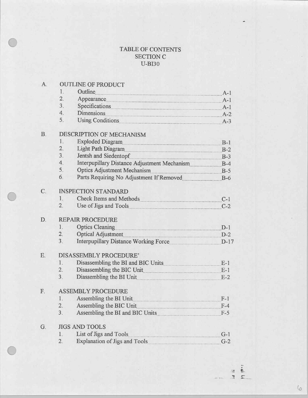
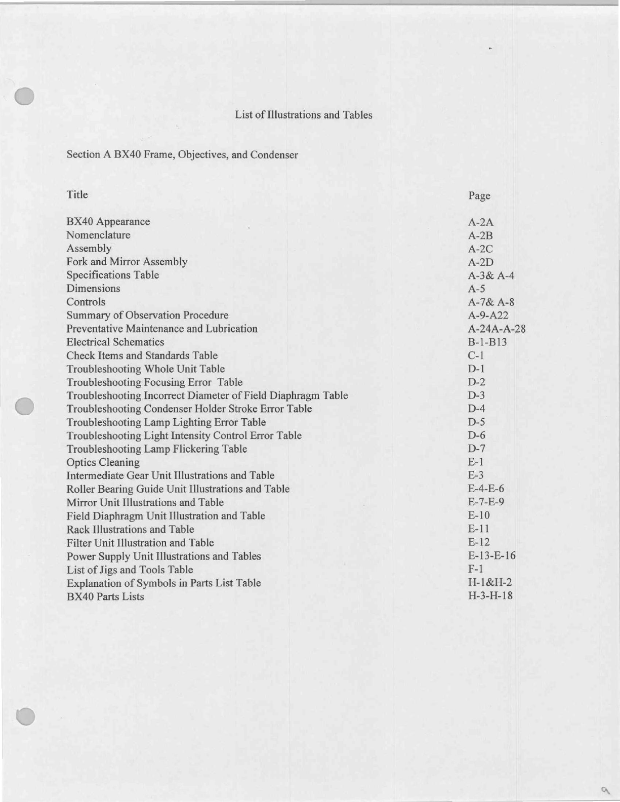
Olympus bx40 User manual

OLYMPUS
BX40
System
Microscope
Servicee
Manual
Olympus
America
Inc.
PID
Service
and
Repair
105
Crossways
Park
Woddbury,
NY
11797
Tel
(800)
446-5967
press
2
X1663,1665
Fax
(516)
364-5907
Jana
tine

TABLE
OF
CONTENTS
FOR
BX40
SERVICE
MANUAL
SECTION
A
BAO
FRAME,
OBJECTIVES,
AND
CONDENSER
SECTION
B
BX40
STAGE
SECTION
C
8140
OBSEVATION
TUBE
SECTION
D
BHGO
FRAME?
*This
section
is
needed
some
of
the
repairs
of
BX40
frame.
Only
refer
to
it
if
given
a
specific
reference
form
Section
A
BX40
Frame.

TABLE
OF
CONTENTS
SECTION
A
BX40F
INTRODUCTION
A.
OUTLINE
OF
PRODUCT
1.
2
9.
Outline
Features
List of
Supplied
Equipment
Appearance
Nomenclature
Assembly
Diagram
Mirror
&
Fork
Assembly
Specifications
Dimensions
Using
Conditions
Control
and
Use
of
Controls
Storage
Information
Preventative
Maintenance
and
Lubrication
B:
DESCRIPTION
OF
MECHANISM
1.
Circuit
Diagram
E
INSPECTION
STANDARD
1.
Check
Items
and
Standards
D.
TROUBLESHOOTING
o
Whole
Unit
Focusing
Error
Incorrect
Diameter
of
Field
Diaphragm
Condenser
Holder
Stroke
Error
A-1A
A-1A
A-1B
A-2A
A-2B
A-2C
A-2D
A-3
A-5
A-6
A-7
A-23
A-24A
B-1
C-1
D-2
D-3
D-4

5.
Lamp
Lighting
Error
D-5
6.
Light
Intensity
Control
Error
D-6
7.
Lamp
Flickering
D-7
B.
REPAIR
PROCEDURE
1.
Optics
Cleaning
E-1
2.
Intermediate
Gear
Unit
E-3
3.
Roller
Bearing
Guide
Unit
E-4
4.
Mirror
Unit
E-7
5.
Field
Diaphragm
Unit
E-10
6.
Rack
E-11
7.
Filter
Unit
E-12
8.
Power
Supply
Unit
E-13
F.
JIGS
AND TOOLS
1.
List
of
Jigs
and
Tools
F-1
2.
Explanation
of
Jigs
and
Tools
F-2
G.
LUBRICANTS
AND
CHEMICALS
1.
List
of
Lubricants
G-1
2.
List
of
Chemicals
G-1
Hi
PARTS
LIST
FOR
BX40
FRAME
1.
Explanation
of
Symbol
in
Parts
List
H-1
2.
Parts
List
for
BX40
Frame
H-3
3.
Parts
List
for
Objectives
H-13
4.
Parts
List
for
WH10X
Eyepiece
H-16
5.
Parts
List
for
U-AC
Condenser
H-17
BX40F.doc
at
li
DEL

TABLE
OFCONTENTS
SECTION
B
BX
STAGE
OUTLINE
OF
PRODUCT
e
Outline
A-1
2
3.
4
REPAIR
PROCEDURE
1
Introduction
ty
ет
B-1
2.
Repair
of
Y-GUIDE
UNIT
res
B-2
3.
Repair
of
X-GUIDE
UNIT
.................
B-6
4
Repair
of
X/Y-KNOB
ASS'Y.
B-10
da
da
meaner
N

TABLE
OF
CONTENTS
SECTION
C
U-BI30
OUTLINE
OF
PRODUCT
順
Outline
A-1
2.
>
4.
SÌ
DESCRIPTION
OF
MECHANISM
jl;
2
3.
4.
5.
6.
INSPECTION
STANDARD
心
Check
Items
and
Method...
で
al
2.
Use
of
Jigs
and
Tools
C-2
mme:
la
li

U-BI30
H.
1.
LUBRICANTS
AND
CHEMICALS
‘ls
List
of
Lubricants
and
Chemicals
H-1
LIST
OF
PARTS
FOR
BX40
OBSERVATION
TUBE
U-BI30
i
Explanation
of
Symbols
in
Parts
List
I-1
2
List of
Parts
for
BX40
Observation
Tube
U-BI30
1-3
ht
dé
yy
Per

TABLE
OF
CONTENTS
SECTION
D
BX50F*
INTRODUCTION
E.
REPAIR
PROCEDURE
4.
Coarse/Fine
Adjustment
Knob
E-8
9.
Condenser
Holder
E-23
Е.
JIGS
AND
TOOLS
2.
Explanation
of
Jigs
and
Tools
F-2
G.
LUBRICANTS
AND
CHEMICALS
1.
List
of
Lubricants
G-1
2.
List
of
Chemicals
G-1
H.
PARTS
LIST
FOR
BX50
FRAME
1.
Explanation
of
Symbol
in
Parts
List
H-1
2.
Parts
List
for
BX50
Frame
H-3
e
All
sections
and
pages
not
needed
for
repair
of
BX40
have
been
removed.

List
of
Illustrations
and
Tables
Section
A
BX40
Frame,
Objectives,
and
Condenser
Title
BX40
Appearance
Nomenclature
Assembly
Fork
and
Mirror
Assembly
Specifications
Table
Dimensions
Controls
Summary
of
Observation
Procedure
Preventative
Maintenance
and
Lubrication
Electrical
Schematics
Check
Items
and
Standards
Table
Troubleshooting
Whole
Unit
Table
Troubleshooting
Focusing
Error
Table
Troubleshooting
Incorrect
Diameter
of
Field
Diaphragm
Table
Troubleshooting
Condenser
Holder
Stroke
Error
Table
Troubleshooting
Lamp
Lighting
Error
Table
Troubleshooting
Light
Intensity
Control
Error
Table
Troubleshooting
Lamp
Flickering
Table
Optics
Cleaning
Intermediate
Gear
Unit
Illustrations
and
Table
Roller
Bearing
Guide
Unit
Illustrations
and
Table
Mirror
Unit
Illustrations
and
Table
Field
Diaphragm
Unit
Illustration
and
Table
Rack
Illustrations
and
Table
Filter
Unit
Illustration
and
Table
Power
Supply
Unit
Illustrations
and
Tables
List
of
Jigs
and
Tools
Table
Explanation
of
Symbols
in
Parts
List
Table
BX40
Parts
Lists
Page
A-2A
A-2B
A-2C
A-2D
A-3&
A-4
A-5
A-7&
A-8
A-9-A22
A-24A-A-28
B-1-B13
C-1
D-1
D-2
D-3
D-4
D-5
D-6
D-7
E-1
E-3
E-4-E-6
E-7-E-9
E-10
E-11
E-12
E-13-E-16
F-1
H-1&H-2
H-3-H-18

List
of
Illustrations
and
Tables
Section
B
BX40
Stage
Title
Specifications
Table
Introduction
Illustration
and
Tables
Y-Guide
Unit
Illustrations
and
Table
X-Guide
Unit
Illustrations
and
Table
X/Y-Knob
Assembly
Illustrations
and
Tables
List
of
Jigs
and
Tools
Illustration
and
Table
Lists
of
Grease
and
Adhesives
Tables
Explanation
of
Symbols
in
Parts
List
Table
Lists
of
Parts
BX40
Stage
Illustrations
Page
A-1&A-2
B-1
B-1-B-5
B-6-B-9
B-10-B-16
C-1
D-1
E-1&E-2
E-3-E14
yO

List
of
Illustrations
and
Tables
Section
C
BX40
Observation
Tube
U-BI30
Title
U-BI30
Appearance
Specifications
Table
Dimensions
U-BI30
Exploded
Diagram
Light
Path
Diagram
Jentsh
and
Siedentopf
Illustration
and
Table
Interpupillary
Distance
Adjustment
Mechanism
Optics
Adjustment
Mechanism
Parts
Requiring
No
Adjustment
If
Removed
Check
Items
and
Methods
Table
Use
of
Jigs
and
Tools
Optics
Cleaning
Optical
Adjustment
Illustrations
and
Tables
Interpupillary
Distance
Working
Force
Disassembling
the
BI
and
BIC
Units
Disassembling
the
BIC
Unit
Disassembling
the
BI
Unit
Assembling
the
BI
Unit
Assembling
the
BIC
Unit
Assembling
the
BI
and
BIC
Units
List
of
Jigs
and
Tools
Table
List
of
Lubricants
and
Chemicals
Table
Explanation
of
Symbols
in
Parts
List
Table
Lists
of
Parts
BX40
U-BI30
Page
A-1
А-1
А-2
B-1
B-2
B-3
B-4
B-5
B-6
C-1
C-2
D-1
D-2-D16
D-17
E-1
E-1
E-2-E-4
F-1-F-4
F-4&F-5
F-5
G-1&G-2
H-1
T-1&I-2
1-3-1-6

List
of
Illustrations
and
Tables
Section
D
BX50
Frame
Title
Coarse/Fine
Adjustment
Knob
Illustration
and
Tables
Condenser
Holder
Illustrations
and
Tables
Explanation
of
Jigs
and
Tools
Illustrations
and
Table
Lists
Lubricants
and
Chemicals
Tables
Explanation
of
Symbols
in
Parts
Lists
Table
Parts
Lists
for
BX50
Frame
Page
E-8-E-14
E-23-E-28
F-2&F-3
G-1
H-1&H-2
H-3-H-6
xv

SECTION
A
THIS
SECTION
CONTAINS
INFORMATION
ON
BX40
FRAME,
OBJECTIVES,
AND
CONDENSER
SEE
TABLE
OF
CONTENTS
NEXT
PAGE

TABLE
OF
CONTENTS
SECTION
A
BX40F
INTRODUCTION
A.
OUTLINE
OF
PRODUCT
1.
2,
δ.
9
Outline
Features
List
of
Supplied
Eguipment
Appearance
Nomenclature
Assembly
Diagram
Mirror
&
Fork
Assembly
Specifications
Dimensions
Using
Conditions
Control
and
Use
of
Controls
Storage
Information
Preventative
Maintenance
and
Lubrication
B.
DESCRIPTION
OF
MECHANISM
1.
Circuit
Diagram
C:
INSPECTION
STANDARD
1.
2
3:
4
Check
Items
and
Standards
TROUBLESHOOTING
1.
Whole
Unit
Focusing
Error
Incorrect
Diameter
of
Field
Diaphragm
Condenser
Holder
Stroke
Error
A-1A
A-1A
A-1B
A-2A
A-2B
A-2C
A-2D
A-3
A-5
A-6
A-7
A-23
A-24A
B-1
C-1
va

5.
Lamp
Lighting
Error
6.
Light
Intensity
Control
Error
7.
Lamp
Flickering
REPAIR
PROCEDURE
1.
Optics
Cleaning
Intermediate
Gear
Unit
Roller
Bearing
Guide
Unit
Mirror
Unit
Field
Diaphragm
Unit
Rack
Filter
Unit
we
xp»
Power
Supply
Unit
JIGS
AND
TOOLS
1.
List
of
Jigs
and
Tools
2.
Explanation
of
Jigs
and
Tools
LUBRICANTS
AND
CHEMICALS
1.
List
of
Lubricants
2.
List
of
Chemicals
PARTS
LIST
FOR
BX40
FRAME
1.
Explanation
of
Symbol
in
Parts
List
2.
Parts
List
for
BX40
Frame
3.
Parts
List
for
Objectives
4.
Parts
List
for
WH10X
Eyepiece
5.
Parts
List
for
U-AC
Condenser
D-5
D-6
D-7
E-1
E-3
E-4
E-7
E-10
E-11
E-12
E-13
H-1
H-3
H-13
H-16
H-17
у
№"!
ja
ld

a
List
of
Illustrations
and
Tables
Section
A
BX40
Frame,
Objectives,
and
Condenser
Title
BX40
Appearance
Nomenclature
Assembly
Fork
and
Mirror
Assembly
Specifications
Table
Dimensions
Controls
Summary
of
Observation
Procedure
Preventative
Maintenance
and
Lubrication
Electrical
Schematics
Check
Items
and
Standards
Table
Troubleshooting
Whole
Unit
Table
Troubleshooting
Focusing
Error
Table
Troubleshooting
Incorrect
Diameter
of
Field
Diaphragm
Table
Troubleshooting
Condenser
Holder
Stroke
Error
Table
Troubleshooting
Lamp
Lighting
Error
Table
Troubleshooting
Light
Intensity
Control
Error
Table
Troubleshooting
Lamp
Flickering
Table
Optics
Cleaning
Intermediate
Gear
Unit
Illustrations
and
Table
Roller
Bearing
Guide
Unit
Illustrations
and
Table
Mirror
Unit
Illustrations
and
Table
Field
Diaphragm
Unit
Illustration
and
Table
Rack
Illustrations
and
Table
Filter
Unit
Illustration
and
Table
Power
Supply
Unit
Illustrations
and
Tables
List
of
Jigs
and
Tools
Table
Explanation
of
Symbols
in
Parts
List
Table
BX40
Parts
Lists
Page
A-2A
A-2B
A-2C
A-2D
A-3&
A-4
A-5
A-7&
A-8
A-9-A22
A-24A-A-28
B-1-B13
C-1
D-1
D-2
D-3
D-4
D-5
D-6
D-7
E-1
E-3
E-4-E-6
E-7-E-9
E-10
E-11
E-12
E-13-E-16
F-1
H-1&H-2
H-3-H-18
NO

BX40F
INTRODUCTION
This
manual
is
written
for the
persons
who
can
repair
the
BH2
series.
Repair
training
is
necessary
for
the
persons
who
have
no
experience
of
repairing
the BH2
series.
*
The
disassembly
and
assembly
procedures
are
simplified
in
this
manual.
Disassemble
the
mechanical
parts
sequentially
from
©
5
Assemble
in
the
reverse
order.
adhesive
and
adjustment
steps.
Pay
attention
to
the
grease,
Disassemble
the
electrical
parts
sequentially
from
@
with
attention
given
to
the
connectors.
Assemble
in
the
reverse
order.
adhesive
and
adjustment
steps.
°
For
the
adjustment,
refer
to
the
following
pages.
[Example]
(Mechanical
parts)
πι
Disassembly
Pay
attention
to
the
connectors,
No.|
Parts
name
Screw
Grease
Adhesive
|
Adjustment
©
BOTTOM
PLATE
|
CUK3x6SA(*1)4
pcs.
©
|
BLIND
SEAL
@
|
LEVER
PUTB3x16SA(*2)1
pc.
|
OT1793
E8-3
(E-22)
SW3SA(*3)
1
pc.
KNW3SA
(*4)
1
pc.
Assembly
Reference
item
———
Reference
page
(Electrical
parts)
No.|
Parts
name
Connectors
Screw
Adjustment
©
POWER
BOARD
(a)
CNl
---
Switch
CSTS3x8SA(*1)2
pes.|
El0-3
(E-32)
(b)
CN2
---
Service
outlet
|
CTK3x4SA(*2)
4
pcs.
(c)
CN20
--
Display
board
(d)
Vout
+
Lamp
(Gray)
(e)
Vout
-
Lamp
(White)

BX40F
JE
A.
OUTLINE
OF
PRODUCT
OUTLINE
(1)
(2)
Application
Clinical
inspection
for
diagnosis
of
disease,
cells,
blood,
etc.
and
general
researches.
Product
range
Replacement
product
range
of
BHT and
BHTU
market.
FEATURES
(1)
(2)
(3)
(4)
(5)
(6)
(7)
(8)
(9)
(10)
(11)
(12)
(13)
(14)
The
field
number
22
(standard
field
of
view)
is
used
to
expand
the
observation
range
20%
compared
with
the
BH2.
The
arm
rest
(base)
is
eliminated
to
allow
the
operator
to
directly
put
his
hand
on
the
table
surface,
minimizing
the
operator's
fatigue
and
improving
the
maneuverability.
The
base-less
structure
expands
the
operation
space.
The
eye
point
height
is
adjustable
to
meet
the
operator
when
combined
with
U-TBI,
minimizing
the
operator's
fatigue
and
improving
the
workability.
The
wide
field
of
view
(field
number
26.5)
is
available
when
combined
with
the
superwide
field
observation
tube.
The
new
glass
material
and
coating
agent
used
in
the
UIS
optics
provide
an
image
with
sharp
contrast.
The
ceramic
coated
stage
is
equipped
as
a
standard
to
minimize
the
friction
of
the
slide
glass
on
the
stage
surface.
(The
wear
resistance
is
improved
to
eight
times
or
more
than
the
BH2-SVR(L).)
The
stage
control
knob's
rotating
force
is
adjustable
by
the
user
(40
~
400g
in
each
of
the
X
and
Y
direction).
The
revolving
nosepiece
facing
the
rear
side
is
used
to
facilitate
visual
inspection
and
marking
of
a
specimen.
Since
the
intermediate
lens
is
not
built
in
the
revolving
nosepiece,
it
prevents
deterioration
of an
image
by
the
intermediate
lens
and
allows
the
U-excited
observation.
The
light
preset
switch
allows
one-touch
switching
to
the
desired
light
level.
(This
is
useful
for
setting
the
color
temperature
of
photography
and
light
intensity
adjustment
when
switching
between
two
objectives.)
The
stage
stroke
is
increased
and
the
interference
between
the
specimen
holder
and the 40x
objective
is
eliminated
to
enable
observation
of
the
whole
surfaces
of
two
slide
glasses.
The
illumination
switch,
the
light
intensity
control
and
the
coarse
and
fine
adjustment
knob
are
located
in
a
concentrated
position
to
allow
operation
by
minimum
handling.
The
advanced
computer
simulation
based
on
the
finite
element
method
(FEM)
is
employed
to
improved
the
rigidity
and
stability
of
the
micro-
scope
frame.
The 30W
halogen
bulb
is
used
to
increase
brightness
and
to
allow
special
observation
such
as
darkfield
and
phase
contrast.
A-1A

OLYMPUS
OLYMPUS AMERICA
INC.
PRECISION
INSTRUMENT
DIVISION
CATALOG
NO.
BX40F3
5-UL103
8-C410
9-U115
Z-89031
3-U123
2-U1002
1-UB223
1-UB227
1-UB235
6-U110
PRODUCT
DESCRIPTION
B-MAX
40
MICROSCOPE
ITEM
LIST
BX40F3:
Microscope
Stand
for
Olympus
B-MAX
modular
system.
Y-shaped
design
provides
exceptional
stability
and
ergonomic
positioning
of
the
coaxial
coarse
and
fine
focus
knobs.
Heavy-duty
nichrome
plated
steel
rack
and
pinion
coarse
focus
gears
move
the
stage
elevation
by
means
of
roller
bearings
over
a
25mm
range.
Fine
focus
graduation:
1
micron
(0.001mm).
Stroke
per
rotation
of
fine
focus:
0.1mm;
stroke
per
rotation
of
coarse
focus:
15mm.
Adjustable
focus
tension
control
and
focus
stop.
The
notched
stage
mount
can
be
detached
for
relocation
15mm
below
the
standard
position,
accommodating
a
specimen
height
of
4Omm.
Mount
for
B-
MAX
series
observation
tube,
rotatable
360
degrees.
Dust-free
design
with
RMS
thread
guintuple
inward-facing
ball-bearing
nosepiece.
Transmitted
light
Koehler
illumination
optics.
On/off
switch;
internal
thyristor
controlled
continuously
variable
6V/30W
DC
power
supply.
The
LED
voltage
display
and
continuously
variable
light
intensity
controls
are
ergonomically
positioned.
The
built-in
intensity
pre-
set
switch
is
adjustable
throughout
the
entire
intensity
range.
Built-in
outlet
for
powering
illuminated
arrow
pointer
of
multi-viewing
attachments.
Built-in
graduated
field
diaphragm;
accepts
optional
attachable
filter
cassette.
Circular
dovetail
stage
mount
accepis
B-MAX
series
interchangeable
stages,
and
permits
rotation
of
stage
about
the
vertical
axis.
Attached
rack
and
pinion
vertical
substage
condenser
mount
with
left
and
right
control
knobs;
26.5mm
condenser
stroke
and
centering
screws.
Includes
dustcover*,
immersion
oil,
instruction
manual,
allen
wrench
and
warranty
card.
(Requires
U-LS30
6V/30W
lamp
socket,
bulb
and
power
cord).
U-LS30:
Lamp
Socket
for
6V/30W
Halogen
Bulb;
precentered;
plugs
into
back
of
B-MAX
40
microscope
stand.
Built-in
louvres
for
convection
cooling.
Easily
removeable
for
bulb
replacement.
6V/30W
Bulb
for
the
B-Max
40
and
IX
50
microscopes.
LBD
filter,
45mm;
for
daylight
color
temperature
conversion.
Dust
Plug
for
Nosepiece.
U-BI30:
Binocular
Observation
Tube
with 30
degree
eyepiece
inclination,
dust-free
design;
F.N.
22
capable;
Siedentopf-type.
For
Olympus
B-MAX
microscopes,
using
30mm
diameter
WH
series
eyepieces.
High
transmission
coated
prisms;
antifungal
treatment.
Graduated
interpupillary
distance
adjustment
50mm-76mm.
Left
eyepiece
tube
with +/-
5
diopter
control.
WH10X-2
Eyepiece:
high
eyepoint,
widefield,
F.N.
22;
30mm
diameter;
with shelf
for
24mm
reticle.
PL10X:
10X
Plan
Achromat
Objective,
infinity-corrected,
F.N.
22;
N.A.
0.25;
W.D.
10.50mm.
PL40X:
40X
Plan
Achromat
Objective,
infinity-corrected,
F.N.
22;
N.A.
0.65;
W.D.
0.56mm;
spring-loaded.
PL100XO:
100X
Plan
Achromat
Oil
Immersion
Objective,
infinity-corrected,
F.N.
22;
N.A.
1.25;
W.D.
0.15mm;
spring-loaded.
U-AC:
Abbe
Condenser,
N.A.
1.25,
oil
immersible.
All
metal
body
with
aperture
iris
diaphragm
graduated
in
numerical
apertures;
detachable
white
cover
to
facilitate
finding
area
to
be
viewed.
Covers
full
field-of-view
with
4X
-
100X
standard
objec-
tives
(F.N.
22)
and 10X
-
100X
objectives
(F.N.
26.5).
A-1B

OLYMPUS
OLYMPUS AMERICA
INC.
PRECISION
INSTRUMENT
DIVISION
CATALOG
NO.
4-U116
4-U191
B-0430
UYPC-15
UYCP-16
Z-85017
PRODUCT
DESCRIPTION
U-SVLS:
Rectangular
Mechanical
Stage
with
left
hand
low
position
coaxial
X
and
Y
controls
and
user-adjustable
torque.
Ultra-durable
ceramic
coated
platform;
180mm
x
135mm.
Y
travel
52mm,
X
travel
76mm.
Rotatable
20
degrees
clockwise,
232
degrees counterclockwise,
with
locking
screw.
X
axis
rack
and
pinion
recessed
into
back
of
stage
plate,
leaving
a
solid,
unbroken
platform
surface,
unaffected
by
dust
or
other
debris.
Uniform
ball
bearing
movement
with
vernier
reading
to
0.1mm.
Detachable
specimen
holder
with
parallel
spring
tension
finger.
U-HL:
Specimen
Holder
with
curved
stainless
steel
finger
on
right
side
allowing
observation
of
the
slide
to
the
very
edge.
Holds
a
2“
x
3"
slide
or
two
back-to-back
1“
x
3"
slides.
BX40
microscope
carrying
case,
will
hold
fully
assembled
microscope
with
pockets
for
extra
bulbs
and
other
supplies,
suitcase
type
with
locks
and
keys.
Power
cord,
15
feet
long
with
green
dot
hospital
plug
for
110
V.
Power
cord,
15
feet
long
with
no
plug
to
be
used
in
location
not
110
V.
Mirror
and
fork
assembly,
40
mm
mirror,
one
side
flat
mirror
and
other
side
concave
mirror,
mounts
in
light
well
to
provide
illumination
when
no
power
source
is
avail-
able.
*
Dustcover
is
plastic
cover
which
is
included
with
the
microscope
stand.
This
is
placed
over
the
microscope
when
not
being
used
to
protect
it.
These
are
the
items
supplied
and
no
other
eguipment
is
reguired
to
operate
the
microscope.
Eguipment
reguired
for
service
is
listed
in
table
1,
Test
Eguipment
and
Tool
Kit
List
in
Medical
Support
Kit
Lists
(DI-ILSS-80865).
A-1C
x
Other manuals for bx40
2
Table of contents
Other Olympus Microscope manuals

Olympus
Olympus IX2-DSU User manual

Olympus
Olympus CH30 User manual

Olympus
Olympus BHSP User manual

Olympus
Olympus U-CBS User manual

Olympus
Olympus BHS User manual

Olympus
Olympus SZX9 User manual

Olympus
Olympus ST. HS User manual

Olympus
Olympus FLUOVIEW FV300 Installation guide

Olympus
Olympus IX2-RFSPOT User manual

Olympus
Olympus Fluoview FV1000 User manual

Olympus
Olympus CHBS User manual

Olympus
Olympus U-DA User manual

Olympus
Olympus FH User manual

Olympus
Olympus FH User manual

Olympus
Olympus VS120 Owner's manual

Olympus
Olympus CX41 User manual

Olympus
Olympus IMT-2 User manual

Olympus
Olympus ORBEYE Manual

Olympus
Olympus BH2 Series Operating instructions

Olympus
Olympus FV3000 User manual