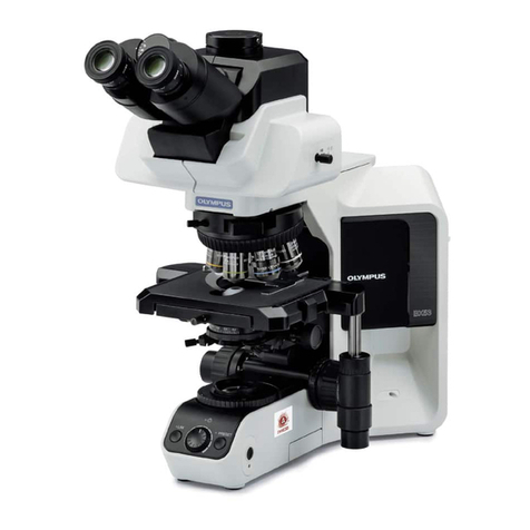
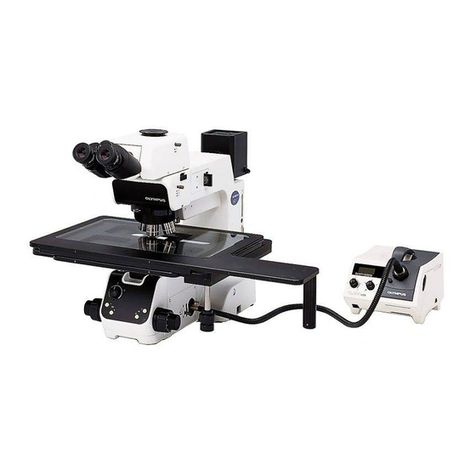
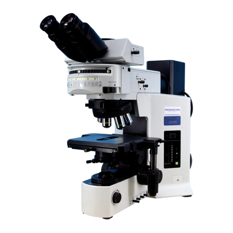
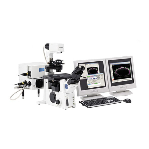
Olympus FLUOVIEW FVMPE-RS User manual

AX8343
Service Manual
FLUOVIEW
FVMPE-RS
Multi Photon Laser Scanning Microscope
Notice
Thank you for your purchase of Olympus microscope at this time.
Retain this manual in an easily accessible place near a system for future reference.
- Research use only -


FVMPE-RS
Important
Caution
This system is a CLASS 4 laser product.
The procedures for using this system are classified as follows:
• Operation
"Operation" means the operations of observation functions using the microscope described in the FVMPE-RS user's
manual provided by Olympus.
CLASS 4 laser light is only emitted from the objective lens during the actual execution.
• Maintenance
“"Maintenance" means the adjustment or other procedures performed by customers to maintain the proper opera-
tions of this system described in the FVMPE-RS User's Manual provided by Olympus.
• Service
"Service" means any adjustment or repair performed by Olympus service personnel or technical personnel who are
provided the service training according to the service manual provided by Olympus.
The performance has influence on the feature of this system, and there is a risk that unintended CLASS 4 laser light is
emitted.
In order to maintain the full performance of this system and ensure your safety, be sure to read this service manual, the
FVMPE-RS user's manual, and the operating instructions for the laser unit and light source unit before use.
For this unit, other than the manuals and instructions above, there is also an on-screen manual ("Online Help") embed-
ded in the software. For details of FV30S-SW and the touch panel controller, refer to Online Help.
Reproduction, copying or duplication of a part or all of this software and manual is prohibited.
This is a Service Manual for Multi Photon Laser Scanning Microscope FVMPE-RS in FLUOVIEW Series.
This manual is intended to be used by Olympus service personnel or technical personnel who are provided the service
training from Olympus.

Registered trademarks
Microsoft, Microsoft Windows, Excel for Windows are registered trademarks of Microsoft Corporation.
Mai Tai®, InSightTM, and DeepSeeTM are registered trademarks of Newport Corporation.
ChameleonTM, OBISTM, and SapphireTM are registered trademarks of Cohelent Inc..
ProScanTM is registered trademark of Prior Scientific Ltd..
Other brand names and product names are trademarks or registered trademarks of their respective owners.
Caution
If the system is used in a manner not specified by this manual, the safety of the user may be imperiled. In addition, the
system may also be damaged. Always use the system as outlined in this instruction manual.
The following symbols are used to set off text in this instruction manual.
: Indicates a potentially hazardous situation which, if not avoided, may result in minor or
serious injuries such as blindness, etc., or damage to the equipment or other property.
It may also be used to alert against unsafe practices.
} : Indicates commentary (for ease of operation and maintenance).
CAUTION

FVMPE-RS
1 Before starting service work ...............................................................................................................................1
1-1 Laser classes and danger levels ..................................................................................................................................................1
2 Service work .........................................................................................................................................................................3
2-1 Work related to the microscope ....................................................................................................................................................3
1 Work related to the nosepiece ...................................................................................................................................................3
2-2 Work related to the illumination......................................................................................................................................................7
1 Changing the halogen bulb ..........................................................................................................................................................7
2 Changing the mercury lamp .........................................................................................................................................................9
2-3 Work related to optical unit ..................................................................................................................................................................11
1 Fluorescence mirror unit ..................................................................................................................................................................12
2 DM unit for the SIM scanner .........................................................................................................................................................14
3 DM unit for external NDD .................................................................................................................................................................16
2-4 Work related to laser introduction ................................................................................................................................................18
1 Opening and closing the laser port (FV30-LPADP) ...................................................................................................18
Contents


FVMPE-RS
1
1 Before starting service work
This system is a Class 4 laser product. These products may expose the human body to dangerous laser beams. Please
be thoroughly informed about laser safety and observe the following precautions when working with these products.
During the service work, be sure to avoid those other than service workers entering around the device.
Before conducting the service work, be sure to perform the works described in "1-5 Confirmation when working with
FVMPE-RS" and "3-3 Completing the observation with this system (Operation)" in [Operation/Maintenance] in FVMPE-RS
User's Manual.
1-1 Laser classes and danger levels
• This system is a Class 4 laser device. Not only direct and specular reflection laser beams but also
diffuse reflection beams are dangerous.
• Only Olympus technical personnel are allowed to assemble and set up this system.
When people who are not Olympus technical personnel did a change (disassembly and modification)
of a device which is not mentioned in this service manual, problems such as system malfunction,
breakage or an accident may occur. We will provide disassembly, relocation and other services for a
fee.
• Keep the objectives away from anything that has a mirror surface.
• Keep the device away from any combustible gas or liquid to prevent fire.
• It is dangerous to remove the objectives, the nosepiece caps and/or nosepiece, as this causes
irradiation of laser beams that are parallel, not diffused.
•
This system uses an IR pulse laser, which has an element of danger to cause blindness if it enters the
eye.
• This system generates laser beams with a near-infrared wavelength, which are invisible and danger-
ous.
• Total laser radiation emitted from this system are as follows:
MPE (Maximum Permissible Exposure) : 0.016 J/m2 (for a single pulse)
0.00005 J/m2 (for a single pulse in the pulse train)
NOHD (Nominal Ocular Hazard Distance) : 50 cm in the vicinity of objective lens *
Exposure duration : 3 X 10⁴ sec
* Hereafter, this area is called “Laser Hazard Area”.
CAUTION
Class Description of danger level
Class 1 Lasers are safe when any kind of optical system is used.
Class 1M Degree of danger is equal to that in Class 1 for naked-eye observation. However, observation through an
optical device is dangerous.
Class 2 This class applies to visible-light lasers with wavelengths of 400 to 700 nm, and safety is ensured by the
aversive reaction of eyes.
Class 2M Degree of danger is equal to that in Class 2, but use of an optical device is dangerous.
Class 3R Direct beam observation is potentially dangerous.
Class 3B Direct beam observation is dangerous.
Class 4
The lights of lasers of this class, being able to cause diffused reflection that is deemed dangerous, pose the
danger of causing fire as well as of damaging skin.
All laser products that can cause an amount of laser light radiation exceeding the accessible emission limit
for class 3B upon human bodies.

2
• Main duties of the laser safety officer to manage lasers are as follows.
Planning and implementing measures for preventing damages due to laser light
Setting and managing laser controlled area
Managing key and so on which starts laser equipment
Inspecting and maintaining laser equipment, and preserving record of them
Inspecting and maintaining protection tool, and observing if it is being used properly
Conducting labor hygiene education and preserving record of it
Other items necessary for preventing damages due to laser light
• Service work is work that can affect the performance of the device and such work is described in this
service manual.
Only Olympus service personnel or technical personnel who are provided the service training by
Olympus are allowed to do the service works according to the procedures described in this service
manual.
• Doing service work by any other procedures than those given in this manual will result in exposure to
dangerous laser radiation.
• During performing service work, do not allow others to enter the periphery of this system except
service workers.
CAUTION

FVMPE-RS
3
I Removing the nosepiece
1) Remove the connector attached to the cable of the nosepiece from the connector secured to the left side of
FV30-RFABXL with the binder.
2) With the motorized focusing knob of the controller (U-MCZ), move the stage apart from the objectives
without hiding the nosepiece mounting screw 1.
3) Fully loosen the nosepiece mounting screw 1 using the Allen screwdriver provided with the system.
4) Gently remove the nosepiece from the front side along the nosepiece mount dovetail.
1 Work related to the nosepiece
1 Removing and mounting the nosepiece
2 Service work
Confirm that the laser is not emitted, and then do the following work.
CAUTION
2-1 Work related to the microscope
} When a nosepiece of a different type from the removed nosepiece is mounted, it is necessary to change
the nosepiece information settings for the touch panel controller. For details, refer to Online Help of the
touch panel controller.
II Mounting the nosepiece
1) With the motorized focusing knob of the controller (U-MCZ), move the stage apart from the objectives
without hiding the nosepiece mounting screw 1.
2) Fully loosen the nosepiece mounting screw 1 using the Allen screwdriver provided with the system.
3) Gently insert the nosepiece from the front side along the nosepiece mount dovetail, and push the
nosepiece until it stops.
4) Tighten the nosepiece mounting screw 1.
5) Connect the connector attached to the cable of the nosepiece to the connector secured to the left side of
FV30-RFABXL with the binder.

4
➀
BX63LF
FV30GF
➀

FVMPE-RS
5
2 Attaching the piezo nosepiece
Attach the piezo nosepiece 1 into the piezo nosepiece adapter 2.
For details of attaching procedures, refer to the instruction manual
provided with the piezo nosepiece (PIFOC(r) P-725K085) of PI co.
Screw the objective lens 3 into the piezo nosepiece 1.
Recommended objective lens
LUMPLFLN60XW*
LUMPLFLN40XW*
XLPLN25XWMP2
XLPLN25XSVMP2
XLSLPLN25XSVMP2
When using the objective lens marked with *, use the RMS adapter
4 (provided with the piezo nosepiece adapter) between the objective
lens and the piezo nosepiece.
1
2
Secure the piezo nosepiece adapter 2 to the arm 1.
Attach the piezo nosepiece adapter to the microscope in the
direction as shown in the picture (The IN/OUT knob of the DIC slider
comes to the right side).
} For attaching procedures, refer to p.3.
3
1
2
3
1
2
4

6
Rotating the piezo nosepiece secured to the illuminator will move
it to the direction you desire. (It is recommended to place the piezo
nosepiece at the back of the objective lens as shown in the picture.)
} For rotation procedures of the piezo nosepiece, refer to the instruc-
tion manual of the piezo nosepiece.
4
Connect the connector of the piezo nosepiece to the piezo nosepiece
exclusive controller.
} For connection procedures, refer to the instruction manual of the
piezo nosepiece.
5
Connect the piezo nosepiece exclusive controller to FV30-ANALOG
with the commercially available BNC cable.
} Connect the control signal input connector (CONTROL IN) of
the piezo nosepiece exclusive controller to the analog output
connector (ANALOG OUT) of FV30-ANALOG.
} When connecting, refer to the instruction manual of the piezo
nosepiece and [7-3 Setting Procedures] in the FVMPE-RS users
manual [Operation/Maintenance].
} Be sure to use the piezo nosepiece exclusive controller with set-
tings described below.
· SERVO ON/OFF toggle switch = ON side
· ANALOG/DIGITAL toggle switch = ANALOG side
· DC-OFFSET knob = Minimum (Position at the end of the
counterclockwise rotation)
6

FVMPE-RS
7
1 Changing the halogen bulb
} The designated bulb model is the 12V100WHAL-L (PHILIPS 7724) or
12V50WHAL-L (LIFE JC) halogen bulb.
Fully loosen the clamping screw ➀ at the top of the halogen lamp
housing using the Allen screwdriver provided with the system.
Lift up the halogen lamp housing 2 to remove it.
Tilt the bulb socket 3 by 90° in the direction of the arrow.
While pushing down the bulb clamping lever 4, hold the halogen
bulb 5 with gloves or a piece of gauze, insert the bulb pins 6
straight and fully into the pin position 7 on the lamp socket.
Then return the lamp clamping lever gently back to the original position
to clamp the bulb.
1
2
3
4
Do not touch the lamp directly.
If fingerprints, etc. are attached, wipe them off completely with
the soft cloth, etc. to prevent the lamp from life reduction or
burst.
CAUTION
Fit the halogen lamp housing from up and tighten the clamping screw
1 by applying downward pressure.
5
1 Changing the lamp
• The bulb, lamp housing and areas near these will be extremely hot during and right after use.
Before replacing the bulb, exit the system and wait until the bulb and the lamp housing are fully
cooled down. Then, replace to the appropriate bulb.
CAUTION
I Changing the halogen bulb
2-2 Work related to the illumination
1
2
3
4
56
7
7

8
} In this chapter, attaching method of the halogen lamp housing
(U-LH100L-3, U-LH100-3) is explained as an example.
Attach the lamp housing a to the FV30-TD b.
Tighten the clamping screw c of FV30-TD using the Allen screwdriver
provided with the system.
1
2
I Attaching the halogen bulb and lamp housing
2 Attaching the lamp housing
c
a
b
a
b
c
d
Remove the collector lens of the U-LH100IR lamp housing a by
loosening the three clamping screws b with an Allen wrench (width
across flats of 2.5 mm).
1
While positioning the 45SCF filter c so that the arrow on its frame
points in the opposite direction of the lamp housing, insert the filter
in the lamp housing, and clamp by tightening the ring spring d
provided with the filter.
Attach the collector lens to the original position.
2
3
3 Attaching the thermal reflection filter 45SCF

FVMPE-RS
9
2 Changing the mercury lamp
• Before replacing the lamp, be sure to turn (OFF) the power
switch and unplug the power cord from the outlet, and wait
(more than 40 minutes as a guide) until the lamp replacement
cover and the lamp are cooled down sufficiently. If you replace
the lamp keeping the power switch “ I ” (ON), the lamp may be
damaged.
• Wear protective gloves and protective glasses when replacing
the lamp.
Use a coin or similar to unlock the lamp replacement cover.
Lift the lamp replacement cover to remove the cover.
Unplug the lamp connector a.
Hold the black frame and raise the lamp slowly upward.
If the lamp is dropped, the glass will break and you may be
injured. Pay careful attention when you replace the lamp.
} Do not touch the glass area of the lamp (front glass or reflector)
directly with bare hands. The lamp may not be used due to the
attached dirt or fingerprints.
Insert a new lamp to the light source unit along the slide rail b.
Connect the lamp connector a.
Mount the lamp replacement cover and lock the lamp replacement
cover with a coin or similar.
Set the power switch to “ I ” (ON). The version of the software is
CAUTION
1
2
3
4
CAUTION
5
6
7
8
2
1
3
45
6
b
a
7
<< Applicable lamp >>
DC130W SHI Lamp (USHIO INC. SHI-130 OL)
1 Replacement of the lamp

10
displayed on the counter (for three seconds). Please remember this
version number.
Example: The version is displayed as follows:
When the version is 1.30 When the version is 1.40
Reset the accumulated lighting time of the lamp. The reset method
differs depending on the version of the software displayed in the
previous step.
Version Reset method
1.30 Press the reset switch for two seconds or
more.
1.40 or later Press the reset switch and the lamp switch at
the same time for five seconds or more.
9
c
c
9
9
Version 1.30
Version 1.40 or later
• Never subject cords and light guides to excessive bending or
twisting because they can easily be damaged.
• Do not turn on the lamp when the light guide is not attached
to the light source. The UV light is included in the lights from
this lamp. Looking directly into the light may damage your eyes.
Also, it could cause fire.
CAUTION
8

FVMPE-RS
11
2-3 Work related to optical unit
Optical unit variation Unit on which the created optical
unit is mounted
Fluorescent mirror unit IX3-FCFPXL
IX3-FGFPXL
IX3-FYFPXL-1-2
IX3-FMCHEXL-1-2
IX3-FUWXL
IX3-FGWXL
IX3-FBVWXL
IX3-FFXL
FV30-RFABXL
Transmitted DIC filter unit U-FDICTIR
IX3-FDICT
FV30-RFABXL
DM unit for SIM scanner FV30-ADM800
FV30-ADMOPT
FV30-HSUMP
DM unit for External NDD
(Non-Descanned Detector)
FV30-NDM690
FV30-NDM760
FV30-NDMVCOIR
FV30-RFABXL
Optical unit variation and unit on which the created optical unit is mounted
} When replacing the optical units with the different types, the nosepiece information set to the touch panel
controller must be changed as well. For details, refer to Online Help of the touch panel controller.

12
1 Attaching and removing to/from FV30-RFABXL
Cover fixing screws
• Make sure not to remove the fluorescence mirror unit mounted on No. 1 in the turret. Do not apply excess
force.
If this fluorescence mirror unit is shifted, the protection for laser safety may be disabled and the optical
performance of LSM could not be guaranteed.
• Before attaching or detaching the fluorescence mirror unit, be sure to engage the shutter in the light path.
• Be sure to exit the FV30S-SW software before attaching/removing the fluorescence mirror unit.
CAUTION
Remove the cover of FV30-RFABXL by loosening the cover fixing screws (two locations) of FV30-RFABXL using
the Allen screwdriver provided with the system.
11
1 Fluorescence mirror unit

FVMPE-RS
13
7
7
4
5
6
a
Rotate the turret by the touch panel controller or the U-MCZ while
checking the display area a of the fluorescence mirror unit No. and
move the fluorescence mirror unit to be replaced to the position on
the front side of the cover.
When rotating the turret, put your fingers away from the turret.
Otherwise, your fingers may be caught.
Hold the sides of the fluorescence mirror unit to be replaced, and
remove it by pulling toward the front side.
Push the fluorescence mirror unit to be used into the space where the
fluorescence mirror unit was removed until it touches the end.
2
CAUTION
3
4
Hold the both right and left sides of the fluorescent mirror unit with
your thumb and the index finger, and shake it gently to make sure that
the fluorescent mirror unit is fixed securely. Without this process, the
fluorescent mirror unit may be attached keeping tilted.
5
After attaching or removing the part, reposition the cover and secure
it by tightening the cover fixing screws using the Allen screwdriver
provided with the system.
6
} Put the hook inside the cover into the groove of the microscope
frame.
} If the power of the system is turned ON, check that the system
starts initializing when the cover is attached.

14
1 Attaching and removing to/from FV30-HSUMP
Attaching and removing the cover
1.
Remove the cover of FV30-HSUMP by loosening the cover fixing screws (four locations) of FV30-HSUMP using the
Allen screwdriver provided with the system.
Cover fixing screws
2 DM unit for the SIM scanner
Table of contents
Other Olympus Microscope manuals

Olympus
Olympus VANOX User manual

Olympus
Olympus SZX7 User manual

Olympus
Olympus Fluoview FV1000 User manual

Olympus
Olympus CK40-TBI Operating instructions

Olympus
Olympus CX31-P User manual

Olympus
Olympus SZX10 User manual

Olympus
Olympus CHA User manual

Olympus
Olympus DSX510 User manual

Olympus
Olympus BX53-P User manual

Olympus
Olympus BX51 User manual

Olympus
Olympus BX3M-CB User manual

Olympus
Olympus CK30 User manual

Olympus
Olympus BHTU-112 User manual

Olympus
Olympus BX-RLA2 User manual

Olympus
Olympus CX21 User manual

Olympus
Olympus VMF User manual

Olympus
Olympus CX43 User manual

Olympus
Olympus IX71 User manual

Olympus
Olympus BX3-URA User manual

Olympus
Olympus DSX1000 User manual