Olympus MU-1 User manual

USA: CAUTION: Federal law restricts this device to sale by or on the order of a physician.
INSTRUCTIONS
MAINTENANCE UNIT
MU-1


Contents
i
MAINTENANCE UNIT MU-1
Contents
Labels and Symbols..................................................................... 1
Important Information — Please Read Before Use.................... 3
Intended Use ............................................................................................ 3
Instruction Manual .................................................................................... 3
User Qualifications ................................................................................... 3
Instrument Compatibility............................................................................ 4
Repair and Modification ........................................................................... 4
Signal Words ............................................................................................ 4
Dangers, Warnings and Cautions ............................................................. 5
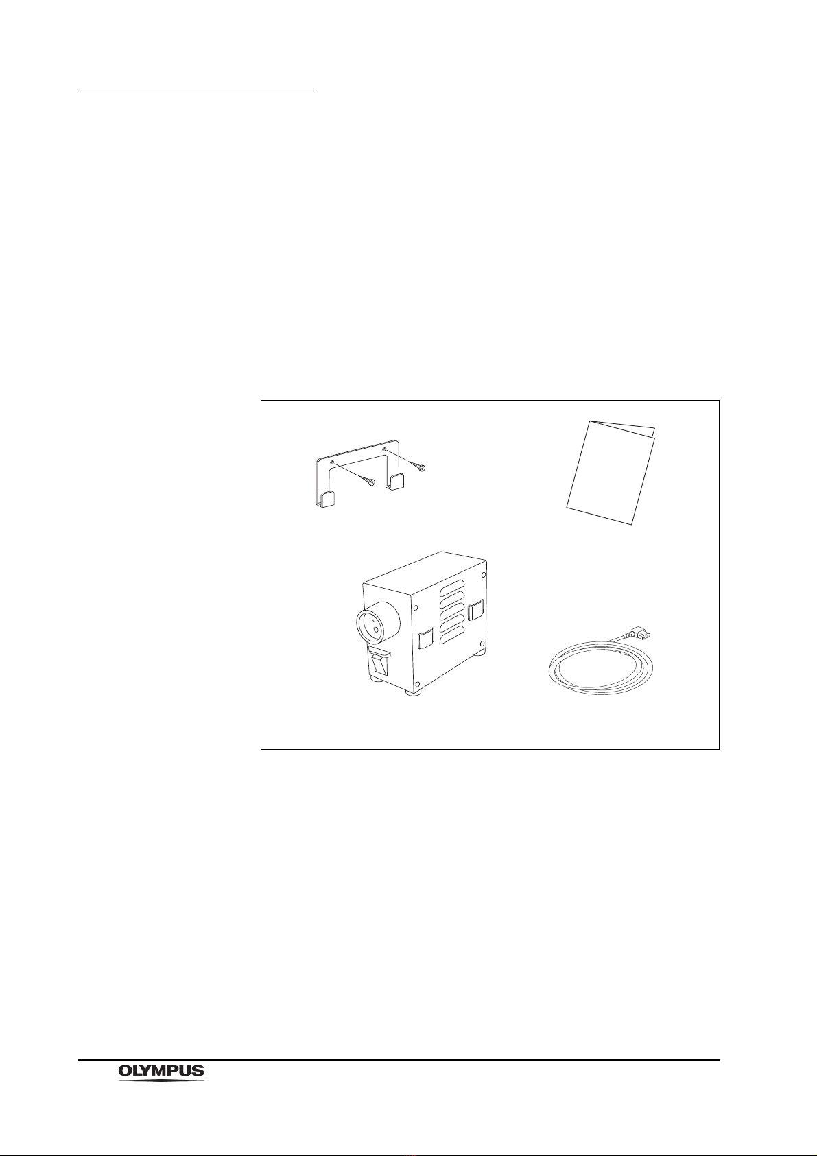
Chapter 1 Checking the Package Contents............................ 6
1.1 Checking the Package Contents..................................................... 6
Chapter 2 Instrument Nomenclature....................................... 7
2.1 Instrument Nomenclature................................................................ 7
Chapter 3 Preparation and Inspection .................................... 9
3.1 Preparation of the Equipment ......................................................... 9
3.2 Preparation and Inspection of the Maintenance Unit ...................... 11
3.3 Preparation and Inspection of the Endoscope and Disinfectant Container
15
Chapter 4 Operation ................................................................. 17
4.1 Leakage Testing ............................................................................. 17
4.2 Remove water from the Air/Water Channel (For endoscope with Air/Water
channel only) ............................................. 18
Chapter 5 Care, Storage and Disposal.................................... 20
5.1 Care ................................................................................................ 20
5.2 Storage ........................................................................................... 21
5.3 Disposal .......................................................................................... 21
Chapter 6 Troubleshooting ...................................................... 22
6.1 Troubleshooting Guide.................................................................... 22
6.2 Returning the Maintenance Unit for Repair..................................... 23
Appendix ....................................................................................... 24
System Chart ........................................................................................... 24
Transportation, Storage and Operating Environments.............................. 26

Contents
ii MAINTENANCE UNIT MU-1
Specifications ........................................................................................... 26

Labels and Symbols
1
MAINTENANCE UNIT MU-1
Labels and Symbols
Safety-related labels are attached to the instrument at the locations shown
below. If labels are missing or illegible, contact Olympus.
Rear side
Electrical Rating Plate
Product name,rated voltage,
and serial number are
described.
1.2 A
1.2 A
Electrical Rating Plate

2
Labels and Symbols
MAINTENANCE UNIT MU-1
Back cover of this instruction manual
Manufacturer
Authorized representative in the European Community

Important Information — Please Read Before Use
3
MAINTENANCE UNIT MU-1
Important Information — Please Read
Before Use
Intended Use
This instrument has been designed to be used with an Olympus endoscope and
other ancillary equipment for Leakage Testing and Remove water from the
Air/Water Channel.
When combined with the optional MB-264 Disinfectant Container, the
endoscope’s Air/Water Channel can be irrigated with 70% ethyl or isopropyl
alcohol to dry the channel.
Do not use this instrument for any purpose other than its intended use.
Instruction Manual
This instruction manual contains essential information on using this instrument
safely and effectively. Before use, thoroughly review this manual and the
manuals of all equipment which will be used during the procedure and use the
instruments as instructed.
Keep this and all related instruction manuals in a safe, accessible location.
If you have any questions or comments about any information in this manual,
please contact Olympus.
Terms Used in This Manual
Wall Mains Outlet
An electrical outlet that has a terminal used exclusively for grounding.
User Qualifications
The operator of this instrument must be a physician or medical personnel under
the supervision of a physician and must have received sufficient training in
clinical endoscopic technique. This manual, therefore, does not explain or
discuss clinical endoscopic procedures.

4
Important Information — Please Read Before Use
MAINTENANCE UNIT MU-1
Instrument Compatibility
Refer to the “System Chart” in Appendix to confirm that this instrument is
compatible with the ancillary equipment being used. Using incompatible
equipment can result in patient or equipment damage.
Repair and Modification
This instrument does not contains any user-serviceable parts. Do not
disassemble, modify or attempt to repair it; patient or user injury and/or
equipment damage can result. If the problems appears minor, refer to Chapter 6,
“Troubleshooting”.
If the problem cannot be resolved by using Chapter 6, contact Olympus.
Signal Words
The following signal words are used throughout this manual:
Indicates an imminently hazardous situation which, if not
avoided, will result in death or serious injury.
Indicates a potentially hazardous situation which, if not
avoided, could result in death or serious injury.
Indicates a potentially hazardous situation which, if not
avoided, may result in minor or moderate injury. It may also
be used to alert against unsafe practices or potential
equipment damage.
Indicates additional helpful information.

Important Information — Please Read Before Use
5
MAINTENANCE UNIT MU-1
Dangers, Warnings and Cautions
Follow the dangers, warnings and cautions described below when handling this
instrument. This information is supplemented by the dangers, warnings and
cautions described in each chapter.
• Follow the following precautions strictly. Failure to do so may
place the patient and medical personnel in danger of an
electrical shock.
Keep liquids away from all electrical equipment. If spilled
fluids enter the unit, stop operation of the equipment at
once and contact Olympus.
Do not prepare, inspect or use this instrument with wet
hands.
• Never use the Maintenance Unit in a flammable or
high-concentration oxygen environment and keep all
flammable gases and liquids or high-concentration oxygen
away from the Maintenance Unit while it is being used.
Explosion or fire may result because the instrument is not
designed to be explosion-proof.
• Be sure to connect the Power Plug of the Power Cord directly
to a grounded Wall Mains Outlet. If the Maintenance Unit is
not grounded properly, it can cause an electric shock or/and
fire.
Do not bend, pull or twist the Power Cord. Electrical shock,
equipment damage or fire can result.
• Alcohol is flammable. Handle with care.
• Do not connect the power cord of the MU-1 to a different
voltage electrical outlet. Fire and smoke may result.

6
Chapter 1 Checking the Package Contents
MAINTENANCE UNIT MU-1
Chapter 1 Checking the Package
Contents
1.1 Checking the Package Contents
Match all items in the package with the components shown below. Inspect each
item for damage. If the instrument is damaged, a component is missing or you
have any questions, do not use the instrument; immediately contact Olympus.
Screw
Hook
Maintenance Unit (MU-1) Power Cord
Instruction Manual

Chapter 2 Instrument Nomenclature
7
MAINTENANCE UNIT MU-1
Chapter 2 Instrument Nomenclature
2.1 Instrument Nomenclature
Front Panel and Side Panel
Hook
Used to attach the Maintenance
Unit to a wall. Use the screws to
attach the Hook to a wall near a
sink.
Output Socket
Accepts the endoscope or
leakage tester and feeds air.
Screw ×2
Power Switch
Switches the power ON and OFF.
The power switch lamp will
illuminate and the unit emits air
from the air pipe in the output
socket when the power is on.
Ventilation Grills
Feet
Attaches the Maintenance Unit to
the hooks or attaches the MB-264
Alcohol Container to the
Maintenance Unit. Brackets are
provided on both sides of the unit.
Attachment Brackets
(provided on both sides)

8
Chapter 2 Instrument Nomenclature
MAINTENANCE UNIT MU-1
Rear Panel
Symbols and Descriptions
Power Switch
ON
OFF
Power Cord Receptacle Circuit Breakers
Protects the Maintenance Unit
and other equipment from
electrical surges.

Chapter 3 Preparation and Inspection
9
MAINTENANCE UNIT MU-1
Chapter 3 Preparation and Inspection
Before each case, prepare and inspect this instrument as
instructed below. Inspect other equipment that are used with
this instrument as instructed in their respective instruction
manuals. Should the slightest irregularity be suspected, do
not use the instrument and see Chapter 6, “Troubleshooting”.
If the irregularity is still suspected after consulting Chapter 6,
contact Olympus.
Damage or irregularity may compromise patient or user
safety and may result in more-severe equipment damage.
Do not connect the power cord of the MU-1 to a different
voltage electrical outlet. Fire and smoke may result.
According to the “System Chart” in the Appendix, prepare this instrument, other
equipment that are used with this instrument, paper towels, basin, gauze and
protective equipment, such as eye wear, a face mask, moisture-resistant clothing
and chemical-resistant gloves, for the procedure.
Refer to the respective instruction manual for each piece of equipment.
3.1 Preparation of the Equipment
Use 70% ethyl or isopropyl alcohol as directed on the
container’s label. Store 70% ethyl or isopropyl alcohol in an
air-tight container. 70% ethyl or isopropyl alcohol stored in an
open container may cause fires and will lose its efficacy due
to evaporation.
Use basins which are at least 40 cm by 40 cm (16” by 16”) in
size and deep enough to allow the endoscope to be
completely immersed. Do not coil the endoscope’s insertion
tube or universal cord with a diameter less than 40 cm.
The endoscope can be damaged if coiled too tightly.

10
Chapter 3 Preparation and Inspection
MAINTENANCE UNIT MU-1
Prepare the following equipment:
Leakage Testing
Remove water from the Air/Water Channel (For endoscope
with Air/Water channel only)
• Personal Protective Equipment
• Water Container
• Maintenance Unit (MU-1)
• Endoscope
• Leakage Tester (MB-155 Optional)
• Water-resistant Cap
(provided with the endoscope,
EVIS Videoscope only)
• Personal Protective Equipment
• Maintenance Unit (MU-1)
• Endoscope
• AW Channel Cleaning Adapter
(provided with the endoscope)
• Alcohol Container
(only when irrigating with 70% ethyl
or isopropyl alcohol)
(MB-264 Optional)
• 70% ethyl or isopropyl alcohol
(only when irrigating with 70% ethyl
or isopropyl alcohol)

Chapter 3 Preparation and Inspection
11
MAINTENANCE UNIT MU-1
3.2 Preparation and Inspection of the Maintenance
Unit
Confirm that the Wall Mains Outlet that you connect the
Maintenance Unit to has more capacity than the total power
consumption of all connected equipment (including this
Maintenance Unit). If the capacity is inadequate, fire can
result or the Circuit Breaker may trip and turn OFF the
Maintenance Unit and all other instruments connected to the
same breaker.
• Do not place the Maintenance Unit on its side or upside
down.
• When installing the Maintenance Unit on the hooks, confirm
that the screws which attach the hooks to the wall are not
loose and that the Maintenance Unit is stable when attached
to the hooks . When a hook comes off, the Maintenance Unit
drops and is damaged, and there is a fear that a user hurt by
the Maintenance Unit which dropped.
• The Maintenance Unit’s Ventilation Grills should be clear of
ancillary equipment. Blockage can cause overheating and
equipment damage.
• Do not connect the power cord of the MU-1 to a different
voltage electrical outlet. Fire and smoke may result.

12
Chapter 3 Preparation and Inspection
MAINTENANCE UNIT MU-1
Installation
Install the Maintenance Unit on the Hook or place the unit on a stable surface in
an area where the unit will not be exposed to the water splashed during
operation. When installing the unit using the feet, confirm that the feet stick firmly
to the installation surface, when attaching the unit to the Hook, confirm that the
screws that attach the Hook to the wall are not loose, and that the Hook does not
move when the unit is attached to it (see Figure 3.1).
Figure 3.1
Connecting the Power Supply
The plug of the power cord that follows the equipment may
vary from this drawing, as in each country the
commercialized cable is in accordance to the local applicable
norm.
1. Confirm the Power Switch is OFF “ ”.
2. Connect the Power Cord to the Power Cord Receptacle.
3. Insert the other end of the Power Cord directly into a Wall Mains Outlet (see
Figure 3.2).
Affix Hook to the wall using
fixing screws provided.
Place unit onto Hook ensuring
brackets are full located.

Chapter 3 Preparation and Inspection
13
MAINTENANCE UNIT MU-1
Figure 3.2
Inspecting the Operation
1. Turn the Power Switch ON “ ”.
2. Confirm that the Power Switch lamp lights and that the pump starts
operating.
3. Confirm that air comes out of the lower hole in the Output Socket (see
Figure 3.3).
4. Turn the Power Switch OFF “ ”.
Figure 3.3

14
Chapter 3 Preparation and Inspection
MAINTENANCE UNIT MU-1
If Power Fails to Come on
If power fails to come on, inspect the system as follows:
1. Confirm that the Power Cord is connected securely to a Wall Mains Outlet
and the Power Cord Receptacle on the Maintenance Unit.
2. Confirm that the Circuit Breakers have not tripped by checking that the
breaker buttons have not popped up. If the buttons have popped up, reset
the breakers according to the following procedure 3. and 4.
Reset the Circuit Breakers only once. If the power is still not
supplied to the Maintenance Unit after resetting the Circuit
Breakers, immediately turn the Power Switch OFF “ ”
disconnect the Power Cord from a Wall Mains Outlet and
contact Olympus. This condition can result in electrical shock
and/or fire.
When the Circuit Breakers trips, do not reset the Circuit
Breakers immediately. Turn the Power Switch OFF “ ”. Wait
at least 15 seconds before resetting the Circuit Breakers to
prevent Circuit Breaker damage.
3. Turn the Power Switch OFF “ ”, disconnect the Power Cord and depress
the Circuit Breaker buttons until it stops with a click.
4. Reconnect the Power Cord and turn the Power Switch ON “ ”. Confirm
that power is being supplied to the Maintenance Unit.

Chapter 3 Preparation and Inspection
15
MAINTENANCE UNIT MU-1
3.3 Preparation and Inspection of the Endoscope
and Disinfectant Container
The Fiberscope Adapter (AC10-S) is not waterproof. Ensure
it is removed before immersing the OES Fiberscope in a
solution.
Leakage Testing
Refer to the instruction manuals of the Leakage Tester and endoscope for
directions on Leakage Testing.
Remove water from the Air/Water Channel (For endoscope
with Air/Water channel only)
1. When using the OES Fiberscope, remove the Fiberscope Adapter from the
Light Guide Connector (if used).
2. Remove the Air/Water Valve from the endoscope and replace it with the AW
Channel Cleaning Adapter (see Figure 3.4).
Figure 3.4

16
Chapter 3 Preparation and Inspection
MAINTENANCE UNIT MU-1
3. Insert the Light Guide Connector as far as it will go into the Output Socket
on the front panel of the Maintenance Unit (see Figure 3.5).
Figure 3.5
Perform the following procedures only when irrigating the channel with 70% ethyl
or isopropyl alcohol. Operate to the Alcohol Container (MB-264) according to the
directions given in it’s instruction manual.
4. Fill the Alcohol Container 70% ethyl or isopropyl alcohol and close the cap.
5. Attach the Alcohol Container to the MU-1’s Container Hanger.
6. Insert the Alcohol Container’s nozzle into the Water Container Connector on
the Light Guide Connector (see Figure 3.6).
Figure 3.6
Other manuals for MU-1
1
Table of contents
Other Olympus Test Equipment manuals
Popular Test Equipment manuals by other brands

Extech Instruments
Extech Instruments ExStik CL200 user manual

Hella Gutmann
Hella Gutmann CSC-Tool SE operating instructions

DeFelsko
DeFelsko PosiTector SST quick guide

Halma
Halma Apollo PP2625 user manual

Kyoritsu Electrical Instruments Works, Ltd.
Kyoritsu Electrical Instruments Works, Ltd. 4200 instruction manual

EMIT
EMIT SmartLog V5 Installation, operation and maintenance