manuals.online logo
Brands
  1. Home
  2. •
  3. Brands
  4. •
  5. OMA
  6. •
  7. Lifting System
  8. •
  9. OMA 537 Instructions for use

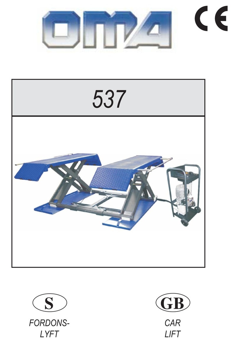
OMA 537 Instructions for use

Other manuals for 537

1

Other OMA Lifting System manuals

OMA 526BLV Guide

OMA

OMA 526BLV Guide

OMA 537 Instructions for use

OMA

OMA 537 Instructions for use

OMA 542 User manual

OMA

OMA 542 User manual

OMA 503 User manual

OMA

OMA 503 User manual

OMA 526 Guide

OMA

OMA 526 Guide

OMA 504A User manual

OMA

OMA 504A User manual

OMA 505C User manual

OMA

OMA 505C User manual

OMA 526L5 User manual

OMA

OMA 526L5 User manual

OMA 502 User manual

OMA

OMA 502 User manual

OMA 528C Guide

OMA

OMA 528C Guide

Popular Lifting System manuals by other brands

probst SDH-H-15 operating instructions

probst

probst SDH-H-15 operating instructions

Bruno OUTDOOR ELITE CRE-2110E Operator's manual

Bruno

Bruno OUTDOOR ELITE CRE-2110E Operator's manual

matev FPS Mounting Assembly Installation Guide

matev

matev FPS Mounting Assembly Installation Guide

Vestil CYL-HLT Series instruction manual

Vestil

Vestil CYL-HLT Series instruction manual

Butts Tools BXS0002 operating instructions

Butts Tools

Butts Tools BXS0002 operating instructions

Safelift MoveAround MA60 Original instructions

Safelift

Safelift MoveAround MA60 Original instructions

Terex Genie Z452513A-48153 Service and repair manual

Terex

Terex Genie Z452513A-48153 Service and repair manual

Granberg InDIago 510 Operating and care instructions

Granberg

Granberg InDIago 510 Operating and care instructions

EUFAB Bike Lift operating instructions

EUFAB

EUFAB Bike Lift operating instructions

morse 82H-124 Operator's manual

morse

morse 82H-124 Operator's manual

Braun NL955 Series Operator's manual

Braun

Braun NL955 Series Operator's manual

Protekt AT 252 instruction manual

Protekt

Protekt AT 252 instruction manual

R. Beck Maschinenbau HS 600 operating manual

R. Beck Maschinenbau

R. Beck Maschinenbau HS 600 operating manual

Nova Technology International, LLC NAS Series quick start guide

Nova Technology International, LLC

Nova Technology International, LLC NAS Series quick start guide

Genie Z-60/34 Operator's manual

Genie

Genie Z-60/34 Operator's manual

Screen Technics INTERFIT Vertical Up Lift instructions

Screen Technics

Screen Technics INTERFIT Vertical Up Lift instructions

Drive DUPONT SAMERY Hermes user manual

Drive

Drive DUPONT SAMERY Hermes user manual

Custom Equipment Hy-Brid 3 Series MAINTENANCE & TROUBLESHOOTING MANUAL

Custom Equipment

Custom Equipment Hy-Brid 3 Series MAINTENANCE & TROUBLESHOOTING MANUAL

manuals.online logo
manuals.online logoBrands
  • About & Mission
  • Contact us
  • Privacy Policy
  • Terms and Conditions

Copyright 2025 Manuals.Online. All Rights Reserved.

I
SOLLEVATORE
PER AUTOVETTURE
GB
CAR
LIFT
537
2
Manuale di istruzioni per l’uso e la manutenzione del
SOLLEVATORE PER AUTOVETTURE
Modello 537
Matricola N°
Anno di costruzione
Costruttore
OMA s.r.l.
Sede centrale: Via Dell’ Artigianato,64
36045 LONIGO(VI) -ITALY
Telefono ++ / +444 / 436199
Telefax ++ / +444 / 436208
1° Emissione - 25 Giugno 1999
CENTRO DI ASSISTENZA
AUTORIZZATO
Rev.1...............................04/11/99
Rev.2...............................06/12/99
Instructions and maintenance manual for
CAR LIFT
Model 537
Serial N°
Year of manufacture
Manufacturer:
OMA s.r.l.
Head Office: Via Dell’ Artigianato,64
36045 LONIGO(VI) -ITALY
Telefono ++ / +444 / 436199
Telefax ++ / +444 / 436208
1° édition - 25th June 1999
AUTHORISED SERVICE CENTRE:
1
Indice
Imballaggio, trasporto e stoccaggioPag. 3
Introduzione Pag. 4
Cap.1 Descrizione della macchinaPag. 5
Cap.2 Specifiche tecniche Pag. 6
Cap.3 Sicurezza Pag . 10
Cap.4 Installazione Pag. 12
Cap.5 Funzionamento ed uso Pag. 13
Cap.6 Manutenzione Pag. 14
Cap. 7 Inconvenienti e rimedi Pag. 15
Contents
Packing, transport and storage Page 3
Introduction Page 4
Chapter 1 Description
of the machine Page 5
Chapter 2 Technical
specifications Page 6
Chapter 3 Safety Page 10
Chapter 4 Installation Page 12
Chapter 5 Operating principles
and use Page 13
Chapter 6 Maintenance Page 14
Chapter 7 Troubleshooting Page15
2
IMBALLAGGIO, TRASPORTO E
STOCCAGGIO.
LE OPERAZIONI DI IMBALLAGGIO, SOLLEVA-
MENTO, MOVIMENTAZIONE, TRASPORTO E DI-
SIMBALLO DEVONO ESSERE AFFIDATE ESCLU-
SIVAMENTE A PERSONALE CHE SIA ESPERTO
IN TALI OPERAZIONI E CHE CONOSCA BENE IL
SOLLEVATORE ED IL PRESENTE MANUALE
IMBALLAGGIO
Il sollevatore viene spedito montato, appoggiato su di un pianale in
legno e avvolto in un unico pacco confezionato con una lastra di
materiale termoretraibile e sigillato con due regge metalliche.
Il peso totale del pacco è di circa 500 Kg.
Fig.1 Movimentazione con carrello elevatore
SOLLEVAMENTO E MOVIMENTAZIONE
I pianali in legno possono essere sollevati sia con carrelli elevatori
(Fig.1) che con gru o carriponte (Fig.2). Nel caso di movimentazio-
ne con gru o carriponte, i pacchi devono essere sempre imbracati
con minimo 2 fasce.
Fig.2 Sollevamento mediante imbracatura
Fig.2 Lifting by slinging
NB. I mezzi scelti devono essere idonei al sollevamento e allo
spostamento in sicurezza, tenendo conto di dimensioni, peso,
baricentro, sporgenze e parti delicate da non danneggiare.
STOCCAGGIO
Gli imballi devono sempre essere conservati in luoghi coperti e pro-
tetti a temperature comprese fra -10°C e +40°C e non devono es-
sere esposti ai raggi diretti del sole.
IMPILAMENTO DEI PACCHI
Il tipo di imballo previsto prevede la possibilità di impilare in magaz-
zino fino a 2 pacchi uno sull’altro, purchè vengano correttamente
disposti ed assicurati contro la caduta.
I pacchi possono essere impilati solamente a condizione che non
siano appoggiati direttamente uno sull’altro ma che vi siano poste
nel mezzo delle traversine in legno come indicato in fig.3
Nei cassoni dei camion o nei containers si possono impilare fino a
2 pacchi, purchè vengano reggiate bene e assicurate contro la ca-
duta.
PACKING, TRANSPORT AND
STORAGE
ALL PACKING, LIFTING, HANDLING, TRAN-
SPORT AND UNPACKING OPERATIONS ARE TO
BE PERFORMED EXCLUSIVELY BY EXPERT
PERSONNEL WITH KNOWLEDGE OF THE LIFT
AND THE CONTENTS OF THIS MANUAL
PACKING
The lift is shipped assembled, resting on a wooden platform and
shrink-wrapped in a single pack and sealed with two metal straps.
The total weight of the pack is approximately 500 kg.
Fig.1 Handling with fork-lift truck
LIFTING AND HANDLING
The wooden platforms can be lifted either with a fork-lift truck (Fig.
1) or with a crane or an overhead travelling crane (Fig. 2). In the
case of handling with a crane or overhead travelling crane, the
packs must always be loaded with at least 2 band.
Fig.3 Impilamento dei sollevatori
Fig.3 Stacking lifts
NB. The chosen means must be suitable for lifting and moving
in safety, taking into account dimensions, weight, centre of
gravity, protrusions and fragile parts not to be damaged.
STORAGE
The packs must always be kept in a covered and sheltered place
at a temperature between -10°C and +40°C and must not be expo-
sed to direct sunlight.
STACKING THE PACKS
This type of packing makes it possible to stack up to 2 packs one
on top of another in a store, provided they are correctly arranged
and secured against falling.
The packs may be stacked only provided they are not resting one
directly on another, but wooden crosspieces are inserted as shown
in Fig. 3.
Up to 2 packs can be stacked in the bodies of lorries or in contai-
ners, provided they are well strapped down and secured against
falling.
3
APERTURA DEGLI IMBALLI
All’arrivo verificare che la macchina non abbia subito danni durante
il trasporto e che ci siano tutti i pezzi indicati nella lista di spedizio-
ne.
Le gabbie devono essere aperte adottando tutte le precauzioni per
evitare danni alle e ai pezzi della macchina .
ELIMINAZIONE DELL’IMBALLO.
Il legno del pallet può essere riutilizzato o riciclato.
INTRODUZIONE
IATTENZIONE
Questo manuale è stato scritto per il personale di officina ad-
detto all’uso del sollevatore (operatore) e per il tecnico addet-
to alla manutenzione ordinaria (manutentore) pertanto, prima
di effettuare qualsiasi operazione sul sollevatore e/o sul suo
imballaggio, occorre leggere attentamente tutto il manuale,
poichè esso contiene informazioni importanti per:
xLA SICUREZZA DELLE PERSONE addette all’uso ed alla
manutenzione ordinaria,
xLA SICUREZZA DEL SOLLEVATORE,
xLA SICUREZZA DEI VEICOLI sollevati.
CONSERVAZIONE DEL MANUALE
Il manuale è parte integrante del sollevatore e deve sempre ac-
compagnarlo, anche in caso di vendita.
Esso deve sempre essere conservato in vicinanza del sollevatore,
in luogo facilmente accessibile.
L’operatore ed il manutentore devono poterlo reperire e consultare
rapidamente in qualsiasi momento.
SI RACCOMANDA, IN PARTICOLARE, UNA LETTURA ATTENTA
E RIPETUTA DEL CAPITOLO 3, CHE CONTIENE IMPORTANTI
INFORMAZIONI E AVVISI RELATIVI ALLA SICUREZZA.
I sollevatori sono stati progettati e costruiti rispettando quanto se-
gue:
LEGGI
Direttive europee: 73/23 CEE - 89/336 CEE e 98/37/CE
NORME TECNICHE
Norne europee : EN 291 /1992, EN 292 / 1992
Norme italiane : UNI 9854
OPENING THE CRATES
When the crates arrive, check that the machine has not been da-
maged during transport and that all parts listed are present.
The crates must be opened using all possible precautionary mea-
sures to avoid damaging the machine or its parts.
DISPOSAL OF CRATES
The wood of the pallet may be re-used or recycled.
INTRODUCTION
ICAUTION
This manual has been written for the workshop personnel as-
signed to using the lift (operator) and for the engineer assi-
gned to routine maintenance (maintenance engineer). Therefo-
re, before doing anything with the lift and/or its packing, it is
necessary to read the entire manual carefully, as it contains
important information for:
xTHE SAFETY OF THE PERSONS assigned to its use and
routine maintenance.
xTHE SAFETY OF THE LIFT.
xTHE SAFETY OF THE LIFTED VEHICLES.
CONSERVATION OF THE MANUAL
The manual is an integral part of the lift and must always ac-
company it, also in the case of sale.
It must always be kept close to the lift, in an easily accessible pla-
ce.
The operator and the maintenance engineer must be able to find it
and refer to it rapidly at any time.
IN PARTICULAR, IT IS RECOMMENDED TO READ CHAPTER 3
CAREFULLY AND REPEATEDLY AS IT CONTAINS IMPORTANT
INFORMATION AND NOTICES RELATIVE TO SAFETY.
The lifts have been designed and manufactured in conformity with
the following:
LAWS
European directives: 89/392 EEC; 91/368 EEC, 93/44 EEC, 93/68
EEC
TECHNICAL STANDARDS
European standards: EN 291/1992, EN 292/1992
Italian standards: UNI 9854
4
CAP.1. DESCRIZIONE DELLA
MACCHINA
Il sollevatore elettroidraulico è fisso, cioè ancorato al suolo ed è
progettato e costruito per il sollevamento e lo stazionamento in
quota di autoveicoli.
Il funzionamento è di tipo elettroidraulico.
Il sollevatore è composto, principalmente dalle seguenti parti:
xgruppo struttura fissa ( basamento )
xgruppi mobili (leve+piani di sollevamento )
xgruppi di sollevamento (cilindri idraulici e centralina);
xquadro comando
xsicurezze.
In figura 4 sono indicate le varie parti che compongono il sollevato-
re.
Fig.4
GRUPPO STRUTTURA FISSA
E’ costituito da un basamento (1) costruito in lamiera di acciaio sal-
data, con fori per il fissaggio al suolo mediante tasselli ad espan-
sione (vedere cap.4 “installazione”). All’interno del basamento si
trovano i fori per l’attacco dei bracci di sollevamento.
GRUPPO MOBILE
E’ costituito da due piattaforme e da bracci in piatto saldato (2),
collegati alle estremità mediante alberi ed ancorati al basamento
tramite supporti in materiale plastico.
Un sistema di sicurezza (3), collegato al braccio trainante e aziona-
to mediante cilindri idraulici, si inserisce automaticamente durante
tutta la fase di salita e blocca il sollevatore durante lo stazionamen-
to in quota.
GRUPPO DI SOLLEVAMENTO
É costituito da 2 cilindri idraulici (4) collegati mediante tubi rigidi e
flessibili ad una centralina idraulica.
Il gruppo di sollevamento è comandato per mezzo di un quadro
elettrico di comando (5) posto su un carrello contenente la centrali-
na.
SICUREZZE
Le sicurezze sono costituite da :
xuna sicurezza meccanica
xuna valvola idraulica di massima pressione
xuna valvola strozzatrice compensatrice che regola la discesa
xun dispositivo acustico
xi salvapiedi
CHAP. 1 DESCRIPTION OF THE
MACHINE
The electro-hydraulic lift, is a fixed installation; this means that it is
anchored to the ground and designed and built for lifting and posi-
tioning automobiles at a certain height off the ground.
The lift is driven by an electro-hydraulic operating system.
The lift consists of the following main parts:
xfixed structure (base);
xmobile units (levers+lifting platforms);
xlift units (hydraulic cylinders and hydraulic unit);
xcontrol box;
xsafety devices.
Figure 4 illustrates the various parts making up the lift.
FIXED FRAMEWORK UNIT
It is composed of a base (1) made of welded steel plates, with ho-
les for fixing to the ground by means of expanding plugs (see chap.
4 “installation”). Inside the base there are holes for the attachment
of the lifting arms.
MOBILE UNIT
It is composed of two platforms and levers of welded steel plates
(2), connected at the ends by means of shafts and connected to
the base by means of special plastic supports. A security system
(3), connected to the towing arm, and driven by means of hydraulic
cylinder, is automatically inserted during the whole lifting phase
and locks the lift during parking at a height.
LIFTING UNIT
It is composed of two hydraulic cylinders (4) connected by rigid and
flexibles tubes.
The lifting unit is controlled by an electric panel (5) placed on a car-
riage containing the hydraulic unit.
SAFETY DEVICES
The safety devices are composed of:
xa sprag to lock the lift at a height.
xa max pressure hydraulic valve
xa compensated throttle valve which adjusts lowering
xan acoustic device
xthe footguards
5
1
2
3
4
5
CAP.2 SPECIFICHE TECNICHE
DATI TECNICI:
Funzionamento ..................................................elettro-idraulico
Portata ................................................................2500 Kg
Alt. max. sollevamento auto................................930 mm.
Alt. min. supporti sollevamento...........................100 mm.
Larghezza pedane...................................... ........450 mm.
Larghezza libera tra pedane....................... ........870 mm.
Tempo di salita....................................................12 sec.
Tempo di discesa................................................35 sec.
Rumorosità..........................................................<74 db
Peso totale..........................................................circa 500 Kg
Temperatura di funzionamento...........................-10°C / +40°C
Ambiente di lavoro: locale chiuso
Fig.5 Dimensioni
del sollevatore
MOTORE ELETTRICO
Tipo ...........................................................G 90 L4
Potenza .....................................................3 Kw
Tensione....................................................230-400 V trif. +/- 5%
Frequenza .................................................50 Hz
N° poli........................................................4
Velocità......................................................1380 giri/1’
Forma costruttiva.......................................B14
Classe isolamento.....................................F
Assorbimento: ...........................................230V: 12,8A
..................................................................400V: 7,4A
OLIO
Il serbatoio dell’olio contiene oilio idraulico a base minerale secon-
do normativa ISO/DIN 6743/4 con grado di contaminazione non
superiore alla classe 18/15 secondo normativa ISO 4406 come IP
HYDRO OIL 32; SHELL TELLUS T 37 o equivalenti.
CHAPTER 2 SPECIFICATIONS
TECHNICAL DATA:
Operation...................................................electro-hydraulic
Carrying Capacity......................................2500 kg
Max. vehicle lifting height ..........................930 mm.
Min. ground clearance of lift structure .......100 mm.
Platform width............................................450 mm.
Effective clearance between platform .......870 mm.
Lift time......................................................12 sec.
Lowering time............................................35 sec.
Noisy level.................................................<74 db
Weight .......................................................500 kg. approx.
Working temperature.................................-10°C / +40°C
Installation requirements: enclosed area.
Fig.5 Lift Dimension
MOTOR
Type ..........................................................G 90 L4
Power ........................................................3 Kw
Voltage ......................................................230-400V th.-ph +/-5%
Frequency .................................................50 Hz
Poles .........................................................4
Speed........................................................1380 rpm
Building shape...........................................B14
Isulation class............................................F
Absorption: ................................................230V: 12,8A
..................................................................400V: 7,4A
OIL
The hydraulic oil tank is filled with mineral oil to ISO/DIN 6743/4,
contamination category no higher tahn class 18/15 according to
ISO 4406, such as IP HYDRO OIL 32; SHELL TELLUS T 37 or an
equivalent oil.
6
SCHEMA IDRAULICO HYDRAULIC DIAGRAM
7
Cilindri di sollevamento
Lifting cylinders
Cilindri di sicurezza
Safety cylinders
Pos. Descrizione Description
1 Serbatoio Tank
2 Filtro aspirazione Filter
3 Pompa Pump
4 Motore immerso Motor
5 Valvola di massima Max pressure valve
6 Modulo Block
7 Valvola di non ritorno Non return valve
8 Valvola regolatore flusso Flow regulator valve
9 Valvola regolatrice manuale Manual flow regulator valve
10 Valvola elettrica Electric valve
11 Valvola di non ritorno pilotata Pilot non return valve
12 Valvola limitatrice di pressione Pressure limiter valve
13 Grani forati Drilling grub screw
14 Grani forati Drilling grub screw
COLLEGAMENTI IDRAULICI HYDRAULIC CONNECTION
8
TO LIFTING CYLINDERS
CYLINDER
CONNECTION
CYLINDER
CONNECTION
TO MECHANICAL SECURITY
1st SAFETY
CYLINDER INLET
2nd SAFETY
CYLINDER INLET
1st SAFETY
CYLINDER OUTLET
Pos. Code Descrizione Description
1 B3081 NIPLO GIUNZIONE 1/4 NIPPLE 1/4
2 R0731 RACCORDO "T" x TUBO Ø8 "T" FITTING PIPE Ø8
3 R0730 RACCORDO "L" A GOMITO x TUBO Ø8 "L" FITTING PIPE Ø8
4 R0729 RACCORDO 1/8 GAS CON
GUARNIZIONE
1/8 GAS FITTING WITH GASKET
5 R0736 TUBO 1/4" R2T06 L=4000mm PIPE 1/4" R2T06 L=4000mm
6 R0735 TUBO 1/4" R2T06 L=1200mm PIPE 1/4" R2T06 L=1200mm
7 R0734 TUBO 1/4" R1T06 L=4350 mm PIPE 1/4" R1T06 L=4350 mm
8 R0733 TUBO 1/4" R1T06 L=1150mm PIPE 1/4" R1T06 L=1150mm
9 R0765 RACCORDO FORATO METRICO M12x1,5 FITTING M12x1,5
10 R0727 TUBO BONDERIZZATO 8x1,5 SX BONDERIZED PIPE 8x1,5 SX
11 R0726 TUBO BONDERIZZATO 8x1,5 DX BONDERIZED PIPE 8x1,5 DX
12 R2205 RONDELLA RAME Ø12x18x1,5 COPPER WASHER Ø12x18x1,5