3
TRASPORTO E
INSTALLAZIONE TRANSPORT AND
INSTALLATION
8OMCA S.r.l - Via Curiel, 6 - 42025 - Cavriago (RE) - ITALY
T
elefono:
+39 0522 943502 / +39 0522 943503 - Website: www.omcasrl.it - E-mail: [email protected]3.3 MOVIMENTAZIONE MACCHINA CON CARRELLO
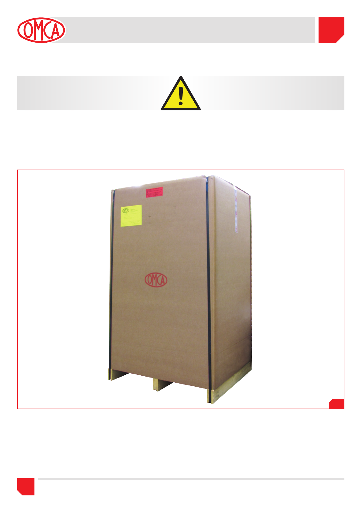
La macchina nasce con il suo carrello ed è preferibile l’utilizzo in questa
configurazione.
Essa può muoversi agevolmente su una pavimentazione regolare
normalmente esistente nelle officine, grazie alle ruote girevoli.
E’ possibile posizionarla nel suo sito di utilizzo semplicemente
spingendola dove desiderato. Solo qualora la pavimentazione risultasse
eccessivamente irregolare rendendo impossibile la rotazione delle
ruote, è necessario l’utilizzo di un dispositivo di sollevamento (Fig.3.2).
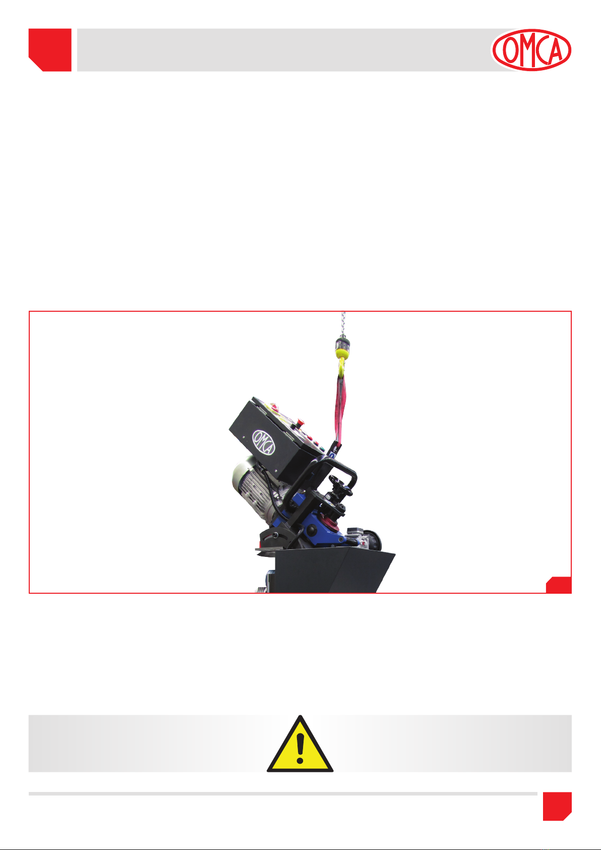
3.4 MOVIMENTAZIONE MACCHINA SENZA CARRELLO
La macchina priva del suo basamento deve essere aggangiata
all’apposito golfare e movimentata con un dispositivo di sollevamento
(Fig.3.2)
.
3.5 INSTALLAZIONE ELETTRICA
La macchina è fornita con cavo di alimentazione:
3 fasi + neutro + , con sezione da 2,5 mm.
Prima dell’allacciamento alla tensione di rete, collegare il cavo di
alimentazione ad una spina di tipo industriale conforme alla norme CEI
EN 60309-1 con 3 fasi + neutro + , tensione di 400 V, portata di
16 A, e grado di protezione almeno IP44.
Fare comunque riferimento allo schema elettrico.
Prima di collegare la macchina alla presa elettrica, accertarsi che
la linea abbia una sezione adeguata alla corrente di impiego della
macchina e che a monte sia presente un dispositivo di protezione
contro i sovraccarichi.
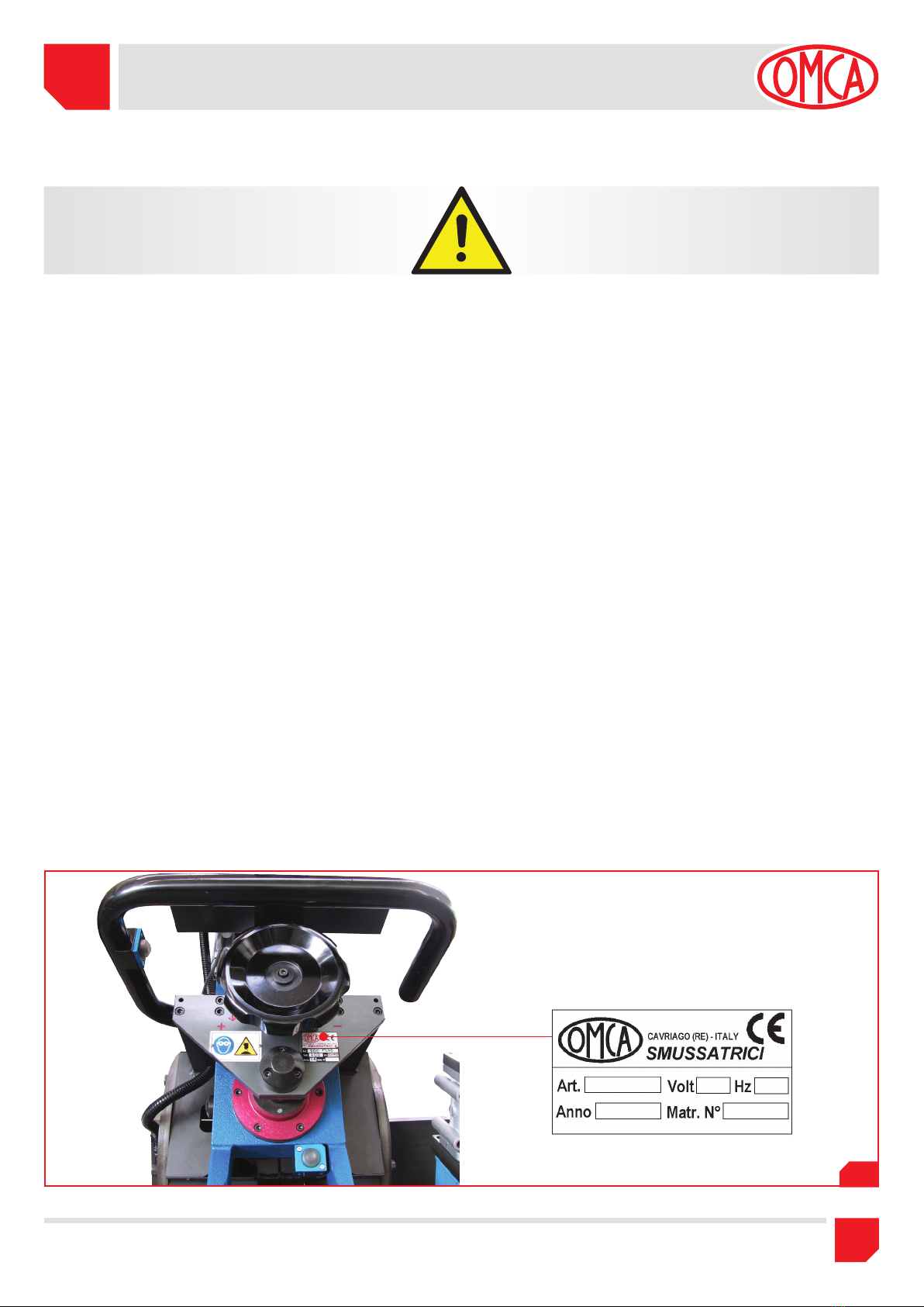
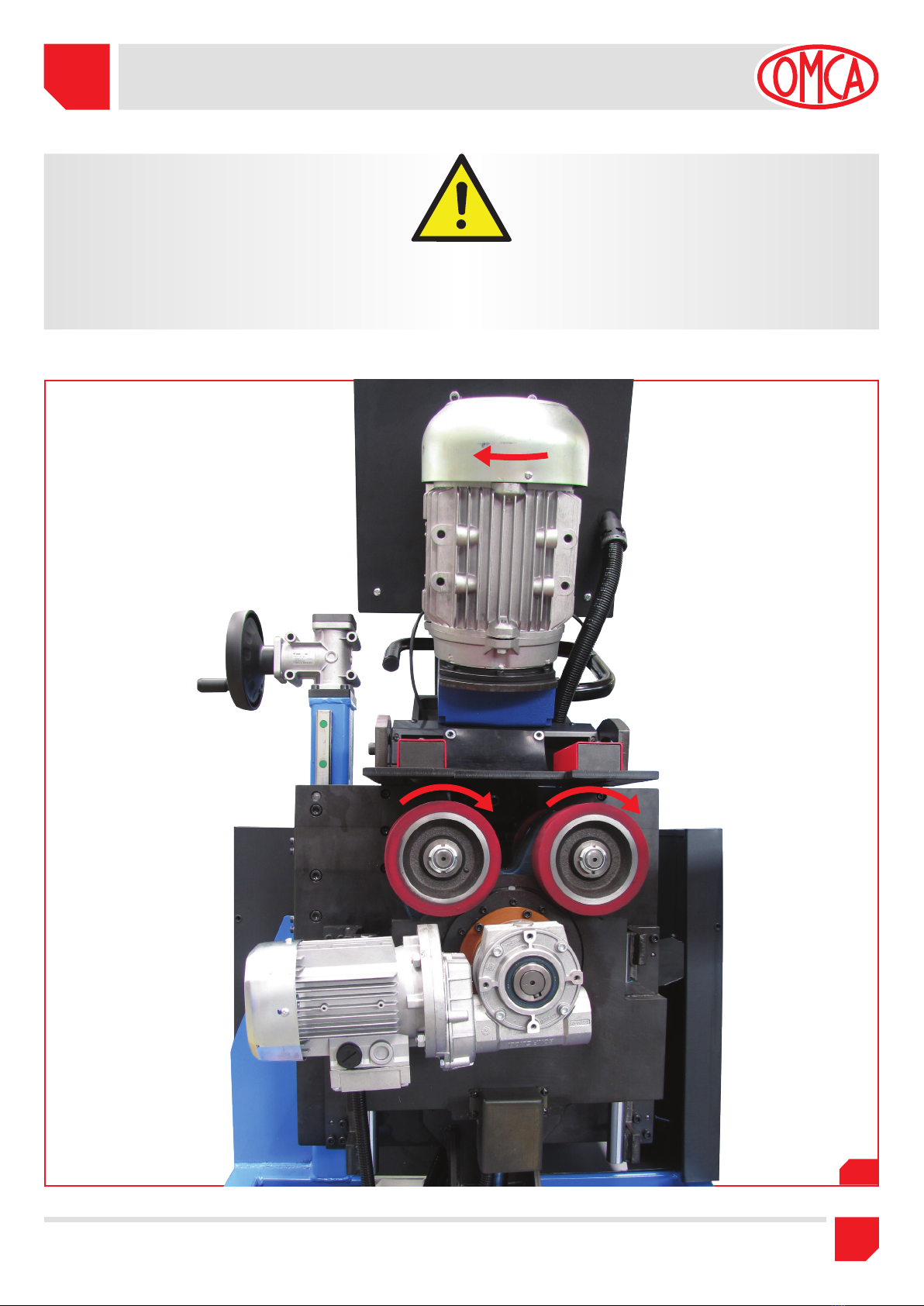
Dopo aver collegato il cavo elettrico alla spina controllare il corretto
senso di rotazione della fresa (come indicato in Fig. 3.3) facendo
girare la macchina a vuoto.
Nel caso di rotazione errata invertire le due fasi nel collegamento della
spina.
L’impianto di terra ed il dispositivo di interruzione a monte della
macchina devono essere coordinati in modo da assicurare la
protezione contro i contatti indiretti secondo la norme CEI 64-8.
Accertarsi che tale protezione sia assicurata mediante un dispositivo
differenziale ad elevata sensibilità (30 mA).
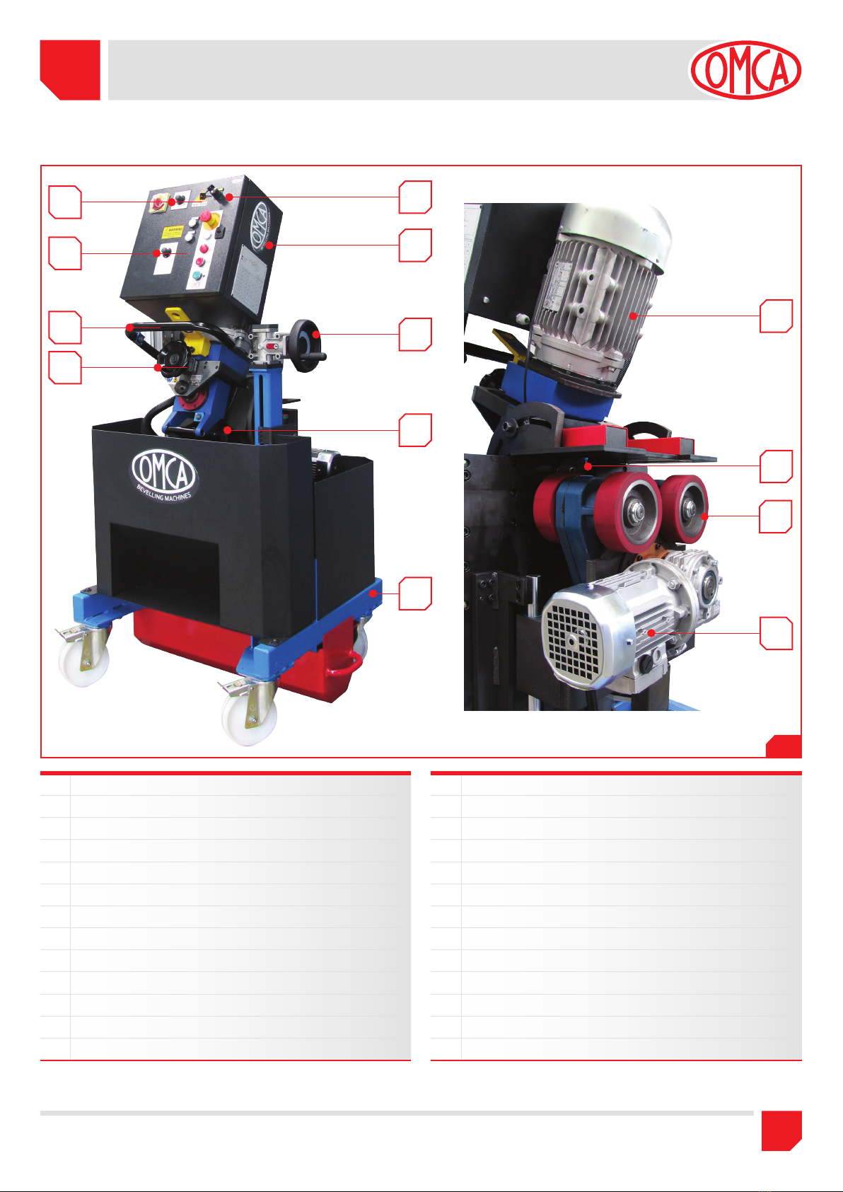
3.3 MACHINE HANDLING WITH TROLLEY
The machine has been designed with its trolley; and it is preferable to
use in this configuration.
The machine can easily move on a regular floor normally present in
the workshop, thanks to swivel wheels.
It’s possible to move the machine by pushing it wherever you desired.
Only in case of irregular floor, making impossible the wheels rotation,
requires the use of a lifting device (Pic.3.2).
3.4 MACHINE HANDLING WITHOUT TROLLEY
The machine without its trolley must be hooked to the relevant eyebolt
and moved with a lifting device
(Pic.3.2)
.
3.5 ELECTRICAL INSTALLATION
The machine is supplied with power cable:
3 Phase + Neutral + 2,5mm. cross section area.
Before connecting to the mains voltage, connect to the power cable
to an industrial plug; in compliance with CEI EN 60309-1 Standard
with 3 Phase + Neutral + , 400 V, 16 Amp, protection class at
least IP44.
Please refer anyway to the electrical diagram.
Before connecting the machine to the mains voltage, make sure that:
the line has suitable square section for the current absorbed by the
machine and that a proper protection device to prevent overloads is
duly installed.
After connecting the power cable to the plug, make sure that the
milling cutter turns in the right direction (as shown in Pic. 3.3) by
running the machine empty.
In case of incorrect rotation reverse the two phases of the plug.
The earthing system and the switching device located above the
machine must be set to ensure protection against indirect contacts,
according to CEI 64-8 Standards.
Make sure that this protection is duly assured by an adequate high
sensivity differential device (30 mA).