Table of Figures
Figure Description Page
Section 1 Introduction
1-1 IEC Symbols ........................................................................................ 1-1
1-2 TJ-USB Overall Dimensions ............................................................. 1-2
1-3 RH-USB Dimensions ......................................................................... 1-2
1-4 UTC-USB Dimensions ....................................................................... 1-3
1-5 PX409-USB Dimensions .................................................................... 1-3
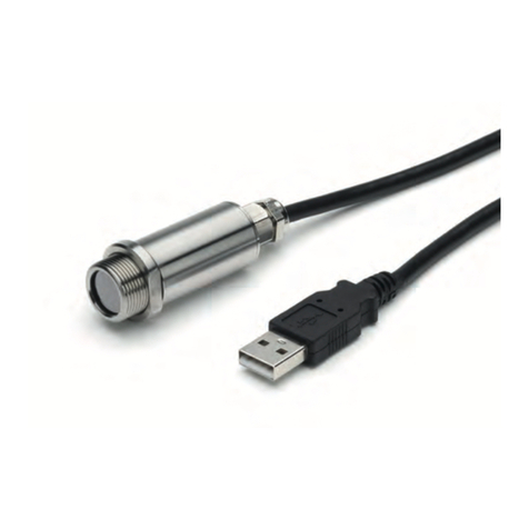
1-6 IR-USB Dimensions ........................................................................... 1-3
Section 2 Hardware
2-1 Mounting Bracket, OS100-MB .......................................................... 2-2
2-2 Water Cooling Jacket, OS100-WC ................................................... 2-3
2-3 Typical Water Cool Jacket Assembly .............................................. 2-3
2-4 Air Purge Collar, OS100-AP.............................................................. 2-3
2-5 Laser Sighting Accessory, OS100-LS ............................................... 2-4
2-6 Laser Warning Label ......................................................................... 2-5
Section 3 Software
3-1 Welcome Screen ................................................................................. 3-1
3-2 Install Options Screen ........................................................................ 3-2
3-3 Select Install Folder Screen ............................................................... 3-2
3-4 License Agreement Screen ................................................................ 3-3
3-5 Confirm Installation Screen .............................................................. 3-3
3-6 Welcome to the Device Driver Installation Wizard Screen ......... 3-4
3-7 Device Driver Installation Wizard Screen ...................................... 3-4
3-8 Completing the Device Driver Installation Wizard Screen ......... 3-5
3-9 Installation Complete Screen ........................................................... 3-5
3-10 Channel Tab Screen ........................................................................... 3-6
3-11 TRH Central Program Screen ........................................................... 3-6
3-12 Channel Configuration Screen.......................................................... 3-7
3-13 Chart TAB Menu Screen ................................................................... 3-8
3-14 Charting Screen .................................................................................. 3-8
3-15 Start Data Logging/Plotting Screen ................................................ 3-9
3-16 Configure Axis Screen ..................................................................... 3-10
3-17 Charting Options Screen ................................................................. 3-10
3-18 Data Log TAB Screen ....................................................................... 3-12
3-19 Data Logging Screen ........................................................................ 3-13
3-20 Start Data Logging/Plotting Screen .............................................. 3-13
Section 4 Specifications
4-1 Optical Field of View ......................................................................... 4-1
ii
USB Series Probes, Sensors, Connectors, and Pressure Transducers
