1. Do not install the product in locations subjected to the following conditions:
・Reflection of intense light (such as other laser beams or electric arc-welding
machines)
・Presence of dust, oil droplets or spray on the filter on the front of the Sensor
Head
・Presence of corrosive or flammable gases
・Direct vibration or shock
2. Pre-installation Checks
・The product cannot accurately measure the following types of objects:
(Transparent objects, objects having an extremely low reflection factor, objects
smaller than the spot diameter, objects with a large curvature, excessively
inclined objects, etc..)
3. Wiring
・Avoid wiring the cable between the Sensor Head and Sensor Controller including
this product near high voltage lines and power lines.
Wiring them together or placing them in the same duct may cause induction,
resulting in malfunction or damage.
・Before connecting/disconnecting the Sensor Head, make sure that the Smart
Sensor is turned OFF. The Smart Sensor may break down if the Sensor Head is
connected or disconnected while the power is ON.
4. Cleaning
・Do not use paint thinner, benzene, acetone or kerosene to clean the Sensor Head.
Doing so will melt the surface of the Sensor Head.
・To remove dust particles, use a blower brush.
・To remove stubborn dirt, wipe gently with a soft cloth moistened with a small
amount of alcohol.
5. Compatibility
・The Sensor Head is compatible with the Sensor Controller, and can be used if
purchased separately.
Please observe the following precautions for safe use of the product:
1. Do not use the product in environments where it can be exposed to
inflammable/explosive gas.
2. Do not disassemble, repair or modify this product.
3. Be sure to make sure that locking mechanisms are locked before use.
4. Dispose of this product as industrial waste.
■Dimensions
PRECAUTIONS ON SAFETY
INSTRUCTION SHEET
©
OMRON Corporation All Rights Reserved.
Model
2007
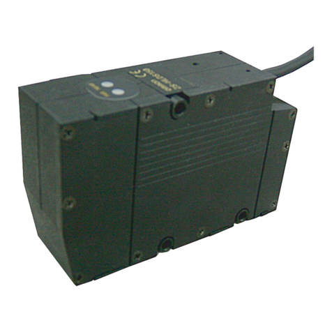
Sensor Head for Smart Sensor ZS-HLDC□□
PRECAUTIONS FOR SAFE USE
PRECAUTIONS FOR CORRECT USE
■Various safety standards regarding laser devices are stipulated depending on the
country of use.
The following describes the method of use according to where the product is exported.
(1) Using in U.S.
When using devices in which ZS-HLDS14AF/T is installed in the U.S., the
devices are subjected to the U.S. FDA laser refutations.
ZS-HLDS14AF/T is classified into Class 2, and reported to CHRD.
Accession Number: 0622389-003
Put the FDA labels (Aperture label, Caution label, Certification and identification
label ).
Please make sure that the label are affixed at the correct locations as indicated.
■Attaching the ferrite core
Attach the ferrite core (provided with the Sensor Head) to both ends of the Sensor
Head cable.
If the ferrite core comes loose from the cable, fasten the ferrite core in place with the
Insure Lock (supplied).
Thank you for selecting OMRON product. This sheet primarily
describes precautions required in installing and operating the product.
Before operating the product, read the sheet thoroughly to acquire
sufficient knowledge of the product. For your convenience, keep the
sheet at your disposal.
●Alert Statements in this Sheet
●Meaning of Alert Symbols
●Meaning of Signal Words
WARNING
Indicates a potentially hazardous situation which, if
not avoided, will result in minor or moderate injury,
or may result in serious injury or death. Additionally,
there may be significant property damage.
WARNING
Never look into the laser beam.
Doing so continuously will result in visual
impairment.
Do not disassemble the product.
Doing so may cause the laser beam to leak,
resulting in the danger of visual impairment.
Indicates the possibility of laser radiation.
Indicates prohibition when there is a risk of minor
injury from electrical shock or other source if the
product is disassembled.
ZS-HLDS14AF/HLDS14AFT
*1 Defined as 1/e2 (13.5 %) of the center optical intensity in the measurement center distance (typical
value). The beam diameter is sometimes influenced by the ambient conditions of the workpiece
such as leaked light from the main beam.
*2
This is the error on the measured value with respect to an ideal straight line. The standard
workpiece is glass. Linearity may change according to the workpiece.
*3 This is the "peak-to-peak" displacement conversion value of the displacement output in the
measuring center distance when the number of samples to average is set to 128, and the measuring
mode is set to the high-resolution mode. The standard workpiece is glass. The minimum
resolution of ZS-HLDS14AFT is 0.25μm regardless of avera
ge count setting.
*4 This is the typical value obtained in the measuring at measuring center distance when the sensor
and workpiece are fixed by an aluminum tool.
*5 This value is obtained when the measuring mode is set to the high speed mode.
(2) Using in a country other than U.S.
・For countries other than Japan and U.S., warning labels must be replaced by
English ones (supplied with the product).
・
EN60825 is provided for products used in Europe, and the content of this standard differs.
The ZS-HLDS14AF/HLDS14AFT is categorized as a Class 2 device as stipulated
in EN60825-1 (IEC60825-1).
■Specifications
(unit: mm)
Accessories
Weight
Cable length
Materials
Shock resistance
(destruction)
Vibration resistance
(destructive)
Degree of protection
Laser label (1 each for JIS/EN, 3 pcs for FDA),
Ferrite core (2 pcs), Insure Lock (2 pcs), Instruction Sheet
Approx. 700 g
0.5 m
Case: aluminum, front cover: glass
150m/s , for 3 times each in X,Y and Z directions
IP40
Ambient humidity
Ambient temperature
Operating
ambient illumination
Operating and storage: 35% to 85% RH
(with no condensation)
Operating: 0 to +50℃, Storage: -15 to +60℃
(with no icing or condensation)
Indicators
FAR
indicator
NEAR
indicator
Sampling cycle (*5)
Temperature
characteristic (*4)
Resolution (*3)
Linearity (*2)
Beam diameter (*1)
Light source
Measuring range
Measuring
center distance
Optical system
Item Model
110μs
±0.05%F.S./℃
0.4μm
±0.2%F.S.
Approx. 25×900μm
Visible semiconductor laser
(wavelength 650 nm, 1mW max. , Class 2)
±0.8mm
14mm
Regular reflection
ZS-HLDS14AF/HLDS14AFT
ZS-HLDS14AF/HLDS14AFT
■Export and Trade Control Laws
The ZS-HLDS14AF is classed as a commodity (or technology) requiring
acquisition of export permission in accordance with foreign exchange and
overseas trade control laws. When the ZS-HLDS14AF is to be taken
outside of Japan, adopt the required procedures such as application for
export permission by the Japanese government.
* Contact your OMRON representative.
■Handling Precautions
・The ZS-HLDS14AF/HLDS14AFT emits a visible laser beam. Do not stare
directly into the laser.
Make sure that the laser beam path is terminated.
A non-reflective matte painted surface is ideal at the end of the laser beam path.
If specular objects are present in the laser beam path, make sure that they are
prevented from reflecting the laser beam. When used without an enclosure, make
sure the laser path from eye level is avoided.
LASER SAFETY
Insulation resistance
Dielectric strength
(destructive)
AC1000V 50/60 Hz 1 min.
20MΩ(by 500V megger)
2
Suitability for Use
s
Omron Companies shall not be responsible for conformity with any standards,
codes or regulations which apply to the combination of the Product in the
Buyer’s application or use of the Product. At Buyer’s request, Omron will
provide applicable third party certification documents identifying ratings and
limitations of use which apply to the Product. This information by itself is not
sufficient for a complete determination of the suitability of the Product in
combination with the end product, machine, system, or other application or
use. Buyer shall be solely responsible for determining appropriateness of the
particular Product with respect to Buyer’s application, product or system.
Buyer shall take application responsibility in all cases.
NEVER USE THE PRODUCT FOR AN APPLICATION INVOLVING
SERIOUS RISK TO LIFE OR PROPERTY WITHOUT ENSURING THAT THE
SYSTEM AS A WHOLE HAS BEEN DESIGNED TO ADDRESS THE RISKS,
AND THAT THE OMRON PRODUCT(S) IS PROPERLY RATED AND
INSTALLED FOR THE INTENDED USE WITHIN THE OVERALL
EQUIPMENT OR SYSTEM.
See also Product catalog for Warranty and Limitation of Liability.
Oct, 2014
D
OMRON Corporation Industrial Automation Company
Contact: www.ia.omron.com
Tokyo, JAPAN
OMRON ELECTRONICS LLC
2895 Greenspoint Parkway, Suite 200
Hoffman Estates, IL 60169 U.S.A.
Tel: (1) 847-843-7900/Fax: (1) 847-843-7787
OMRON ASIA PACIFIC PTE. LTD.
No. 438A Alexandra Road # 05-05/08 (Lobby 2),
Alexandra Technopark,
Singapore 119967
Tel: (65) 6835-3011/Fax: (65) 6835-2711
OMRON (CHINA) CO., LTD.
Room 2211, Bank of China Tower,
200 Yin Cheng Zhong Road,
PuDong New Area, Shanghai, 200120, China
Tel: (86) 21-5037-2222/Fax: (86) 21-5037-2200
OMRON EUROPE B.V.
Sensor Business Unit
Carl-Benz-Str. 4, D-71154 Nufringen, Germany
Tel: (49) 7032-811-0/Fax: (49) 7032-811-199
Regional Headquarters
Lit near measuring center distance, and nearer than
measuring center distance inside the measuring range
Blinks when the measurement target is outside of the
measuring range or when the received light amount is
insufficient
Lit near measuring center distance, and further than
measuring center distance inside the measuring range
Blinks when the measurement target is outside of the
measuring range or when the received light amount is
insufficient
Illumination on received light surface 3000 lx or less
(incandescent light)
10 to 150 Hz, 0.35-mm half amplitude 80 min each in
X, Y, and Z directions
46
18
7
LIGHTENING
PART
RECEIVING
PART
30
53
39±0.1
70±0.1
STANDARD
SURFACE
CONNECTOR
VINYL INSULATED ROUND CORD Dial.6.2
LENGTH 0.5m
LIGHTENING
AXIS
CENTER
RECEIVING
AXIS
570
80
42 4 33.5
3
14 49
39
(28.4)
(12.5)
4-Dia.4.5 MOUNTING HOLES
5
52
109.5
127
10.5 (10.5)
127±0.1
109.5±0.1
30.1
28.9
35
40
77.5
92
137
8.5
100°
2-R6
RANGE
INDICATOR
4-M4
MOUNTING SCREW HOLES
Ferrite core Insure Lock Ferrite core
CAUTION
PEAK POWER
PULSE DURATION
WAVELENGTH
1000
10000
650
μw
μs
This laser product complies with
21 CFR 1040.10 and 1040.11.
Shiokoji Horikawa, Shimogyo-ku,
Kyoto 600-8530 JAPAN
OMRON Corporation
AYABE Factory, OMRON Corp.
Place of manufacture:
Manufactured in
Class 2 Caution Label
Certification Label
Laser Emission
Opening Label
AVOID
EXPOSURE
Laser radiation
is emitted from
this aperture
