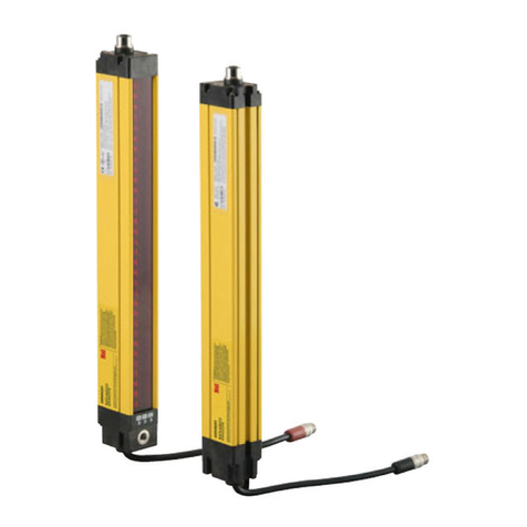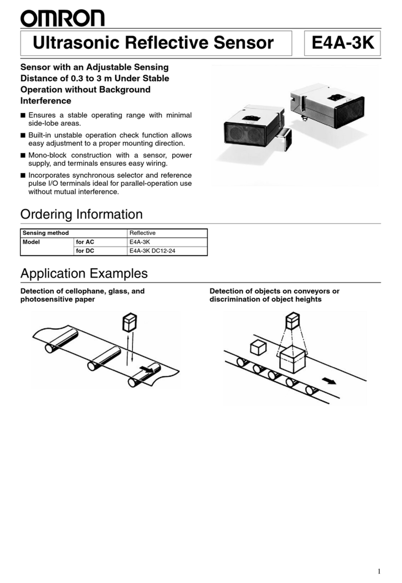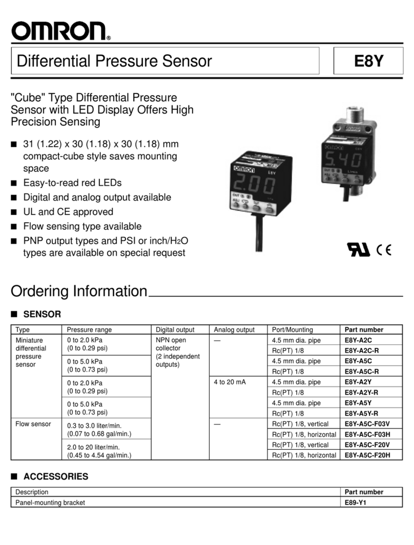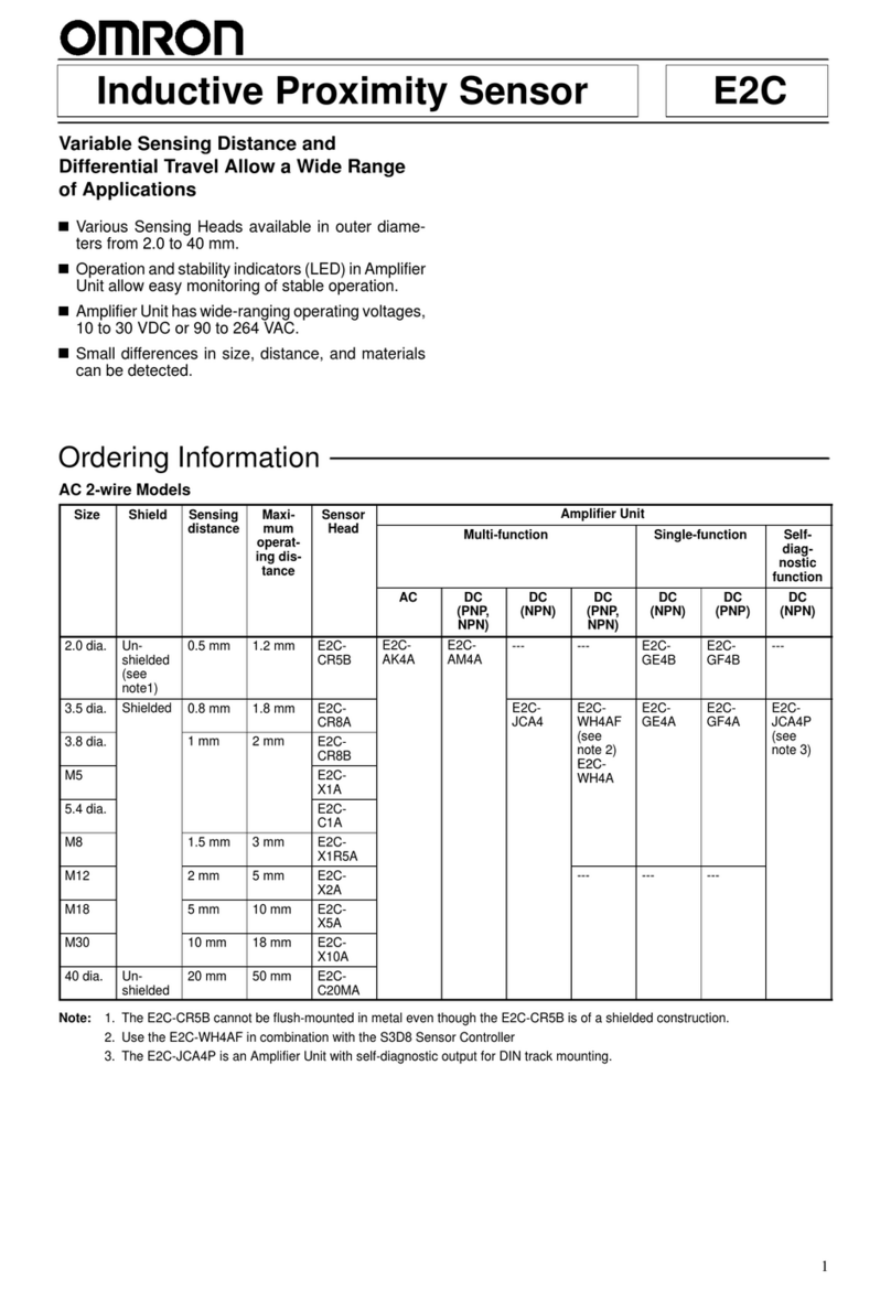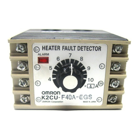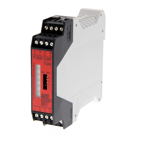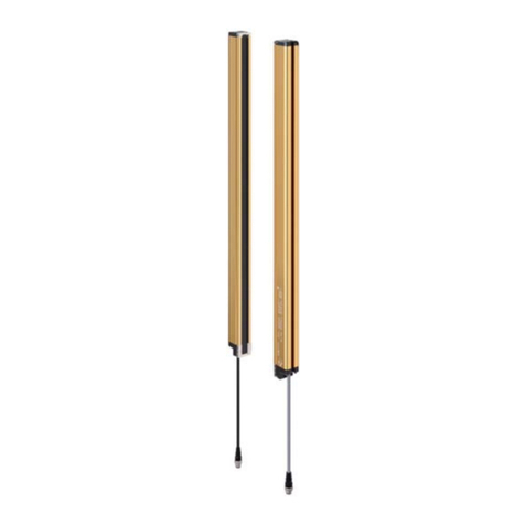
8Single-beam Safety Sensor E3FS
Ratings and Performance
E3FS-10B4 2M/E3FS-10B4-M1-M
Engineering Data
Sensing method Through-beam
Controller F3SX Series
Supply voltage 24 VDC±10% (ripple p-p 10% max.) (Connect the Sensor to an F3SX to use it as a safety device or
as part of a safety system.)
Effective aperture angle (EAA) ±5°(at 3 m)
Current consumption Emitter: 50 mA max.
Receiver: 25 mA max.
Sensing distance 10 m
Standard sensing object Opaque object: 11 mm min. in diameter
Response time 2.0 ms (E3FS only) (Depends on the F3SX model when the Sensor is connected to an F3SX.
Refer to the F3SX operation manual for details.)
Control output
PNP transistor output, load current: 100 mA max., residual voltage: 2 V max.
(except for voltage drop due to cable extension)
(Connect the Sensor to an F3SX to use it as a safety device or as part of a safety system.)
Test input (Emitter)
21.5 to 24 VDC: Emitter OFF (source current: 3 mA max.)
Open or 0 to 2.5 V: Emitter ON (leakage current: 0.1 mA max.)
(Connect the Sensor to an F3SX to use it as a safety device or as part of a safety system.)
Power supply reset time 100 ms
Ambient light intensity Incandescent lamp: 3000 lx max. (light intensity on the receiver surface)
Sunlight: 10,000 lx max. (light intensity on the receiver surface)
Ambient temperature Operating: −10 to 55°C, storage: −30 to 70°C (with no icing or condensation)
Ambient humidity Operating: 35% to 85%, storage: 35% to 95% (with no icing or condensation)
Insulation resistance 20 MΩmin. (at 500 VDC)
Dielectric strength 1000 VAC 50/60 Hz 1 min
Vibration
resistance
Malfunction 10 to 55 Hz, double amplitude: 1.5 mm, 2 h each in the X, Y, and Z directions
Operating limit 10 to 55 Hz, double amplitude: 0.7 mm, 50 min each in the X, Y, and Z directions
Shock
resistance
Malfunction 500 m/s2(approx. 50 G), 3 times each in the X, Y, and Z directions
Operating limit 100 m/s2(approx. 10 G), 1000 times in the X, Y, and Z directions
Degree of protection IP67 (IEC standard)
Light source Infrared LED
Operation indicators Emitter: Emitting (orange)
Receiver: Output ON (green), Output OFF (red)
Protection Output short-circuit protection, reverse polarity protection
Weight (in packaging) E3FS-10B4 2M (ABS resin case): approx. 150 g for 1 set (weight without cable: approx. 55 g)
E3FS-10B4-M1-M (metal case): approx. 125 g for 1 set
Applicable standard IEC61496-1, EN61496-1 Type 2 ESPE (Electro-Sensitive Protective Equipment)
IEC61496-2, prEN61496-2 Type 2 AOPD (Active Opto-electronic Protective Devices)
Accessories Emitter, two nuts for mounting the Receiver, and an instruction manual
Parallel Operating Range Mutual Interference Range Reception Light Output Margin
600
400
200
0
−200
−400
−600 128104620
Distance X
m
Operating position Y (mm)
Y
X
Emitter
Receiver
800
600
400
200
0
−200
−400
−600
−800
128104620
Distance X (m)
Mutual interference range Y (mm)
Y
XEmitter
Receiver
10
9
8
7
6
5
4
3
2
1
03020 2510 1550
Distance
m
Reception Light output margin
