Picking instruction input Open collector with relay or
transistor input
・Indicator ON: Input voltage of 0 to 2V
・Indicator OFF: Open (leakage current 0.1mA max.)
Model
F3W-D052B□
Model
F3W-D052A□
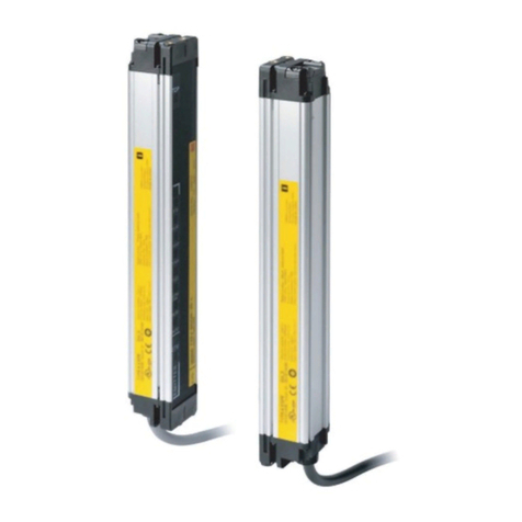
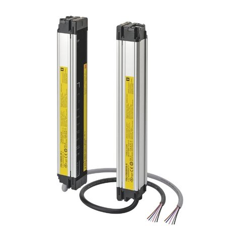
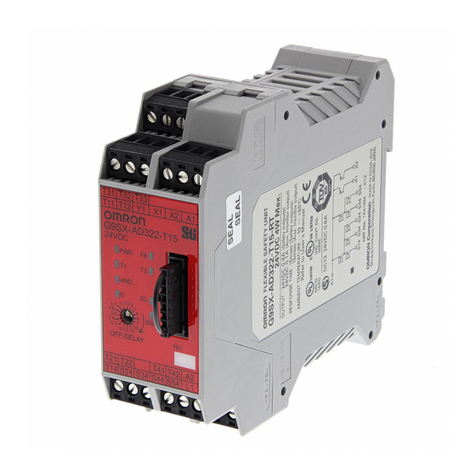
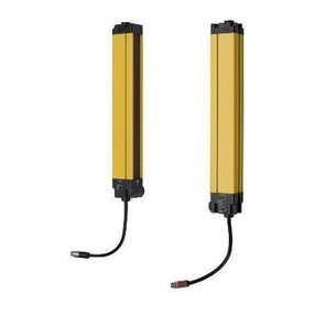
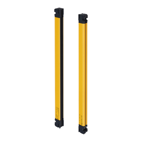
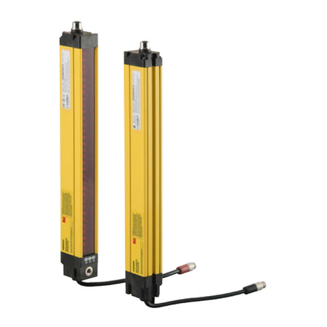
Slim type Picking Sensor
ON
OFF
OFF
ON
Operation
Release
ON
Open
OFF
ON
OFF
0V
■Operation mode / Timing chart
■Picking instruction input / Timing chart
Mode selector
State of output
transistor
Timing chart
Timing chart
L・ON
Light ON
No optical axis
is interrupted
Light
incident
Piking
indicator 6
Power
indicator
B Frequency
indicator
Output
indicator
Output transistor
Picking Instruction
input
External Picking
Indicator output
Picking Indicator
Load(e.g.,relay)
One opetical axis or
more is interrupted
ON
OFF
OFF
ON
Operation
Release
No optical axis
is interrupted
Light
incident
Output
indicator
Output transistor
Load(e.g.,relay)
One opetical axis or
more is interrupted
D・ON
Dark ON
■Rating
Item
Connectin method
Light source
Power supply voltage
Power consumption
Sensing distance
Optical axis pitch
No.of optical axes
Sensing width
Sensing object
Response time
Control output
Operation mode
Sensing method
Model
indicator Receiver
Emitter
Ambient humidity
Degree of protection
Insulation resistance
Dielectric strength
Vibration resistance (destruction)
Shock resistance (destruction)
Through-beam
Infrared LED (860nm)
12 to 24 V DC±10%(ripple range (p-p):10%max.)
Emitter:0.6W max. Receiver:0.7W max.
3m(Long mode:1 to 3m/Short mode:0.05 to 1m switch selectable)
25mm
5
100mm
Opaque,35mm dia.min.
ON/OFF:10ms max.
NPN open collector:30V DC.100mA max.residual voltage 1V max.
D・ON/L・ON switch selectable
Output indicator (orangeLED),Stability incident indicator (green LED),Picking indicator (orange LED,6)
Power indicator (green LED),B Frequency indicator (green LED),Picking indicator(orange LED,6)
−10 to 55℃(with no icing)
−25 to 70℃
35 to 85% RH (with no condensation)
IEC60529:IP62 (with switch cover in place)
20MΩmin. (at 500 V DC)
1,000V AC 50/60Hz for 1 min.
10 to 50 Hz,1.5mm double-amplitude for 2h each in X,Y and Z directions.
500m/s2,3times each in X,Y and Z directions.
F3W-D052A (P)*
Pre-wired
F3W-D052B (P)*
Connector-mounted cord (M12)
SW1
Receiver Emitter
Receiver
Main
circuit
(2)
Pink
(2)
Pink
(3)
Blue
(4)
Black
(1)
Brown
(1)
Brown
(5)
(3)
Blue
Picking
instruction
input
12 to 24V
DC
Stability
incident
indicator
5V
5V
Output
indicator
Picking
indicator,6
F3W-D052A□-D/B□-D
F3W-D052A□-L/B□-L
*
O
N
1
2
3
4
5
6
O
N
1
2
3
4
5
6
O
N
1
2
3
4
5
6
■Mode selector
■Output circuit
*1 Speed differs by displayed mode
*2 It is only in the F3W-D052□P-L.
*The inside of the speck chain line is only F3W-D052AP-L/BP-L.
Numerical value inside parenthesis,( ),indicates a pin number of the connector of the Sensor.
*F3W-D052AP and BP have the external picking indicator output of the following specifications:
-Connection method cord.
-Electric Specifications Output current:50mA max. Output voltage:the sensor power supply voltage.
・Emitter
・Picking indicator mode selection
・Receiver
SW1 No.
3
4
5
1
2
Contents OFF(Left)ON(Right)
FLASH PATTERN
(Picking indicator mode selection)
NC
EXT FLASH PATTERN
(
External picking indicator mode selection
)*2
FLASH TIME
(Display cycle speed selection)*1
Refer to below
Light
Frequency A Frequency B
Flash
SLOW FAST
SW1 No.
3
1
2
4
5
6
Contents OFF(Left)ON(Right)
FLASH PATTERN
(Picking indicator mode selection)
Operation mode selection
Distance(Sensitivily) selection
NC
D・ON
LONG(1〜3m)
L・ON
SHORT(0.05〜1m)
FLASH TIME
(Display cycle speed selection)*1
Refer to below
SLOW FAST
− −
− −
OFF
ON
OFF
ON
OFF
OFF
ON
ON
All ON (6 indicators will be lit)
All Flashing (6 indicators will be flickering same time)
Up-down ON (Two indicators will be lit first up, then down and up)
Center-cross ON
SW1-1 SW1-2 FLASH PATTERN
Orange/purple
(5)
Orange/purple
Load
Control
Output
Sync. line
140
140
77.5
77.5
5×9=45
5×9=45
9
9
4.5 13
4.5
13
Output indicator
Vinyl insulated round
cord 4 dia. 5cores
Standard length 5m
Vinyl insulated round
cord 4 dia. 4cores
Standard length 5m
Stadility incident
indicaror
Power indicator
B Frequency
indicator
10
10
2-4.5 dia.
2-4.5 dia.
4.7
4.7
45°
45°
15
15
25
25
4×25=100
4×25=100
130
130
30
30
6-Picking
indicator
6-Picking
indicator
Optical axis
Optical axis
2-M4 nut spot
facing (depth 3.5)
2-M4 nut spot
facing (depth 3.5)
2-M4 nut spot
facing (depth 1)
2-M4 nut spot
facing (depth 1)
2
15.75
18 6
2
15.75
18
6
130
130
2-M4
2-M4
Mounting scerws holes
Mounting scerws holes
18
18
1
1
5
5
14
Vinyl insulated round cord
4 dia. Standard length 0.3m
■Dimensions
・F3W-D052A□-D(Pre-Wired / Receiver)
・F3W-D052A-L(Pre-Wired / Emitter)
・F3W-D052□P-L
(External picking indicator output type)
Emitter has the following code. Other
dimensions are the same as the dimensions of
F3W-D052A-L
・F3W-D052B□-□
(Connector-mounted cord type)
All dimensions other than connector are the same as
the dimensions of F3W-D052A□-□(Standard
cord length:2m)
*Recommended connector is XS2F-D5□□or
XS2R-D5□□ .
M12×1
44.7
φ14.9
1
4
5
3
2
Connector for F3W-D052B□-□
Operation
Storage
Ambient
temperature
6FREQUENCY
(
see Mutual Interference prevention function
)
Emitter
Main
circuit
External
Picking
Indicator
output
Brown
Load
Blue
© OMRON Corporation 1999-2016 All Rights Reserved.
INSTRUCTION SHEET
Thank you for selecting OMRON product. This sheet pri-
marily describes precautions required in installing and
operating the product.
Before operating the product, read the sheet thoroughly to
acquire sufficient knowledge of the product. For your con-
venience, keep the sheet at your disposal.
Suitability for Use
s
Omron Companies shall not be responsible for
conformity with any standards, codes or regulations
which apply to the combination of the Product in the
Buyer’s application or use of the Product. At Buyer’s
request, Omron will provide applicable third party
certification documents identifying ratings and
limitations of use which apply to the Product. This
information by itself is not sufficient for a complete
determination of the suitability of the Product in
combination with the end product, machine, system,
or other application or use. Buyer shall be solely
responsible for determining appropriateness of the
particular Product with respect to Buyer’s
application, product or system. Buyer shall take
application responsibility in all cases.
NEVER USE THE PRODUCT FOR AN
APPLICATION INVOLVING SERIOUS RISK TO
LIFE OR PROPERTY WITHOUT ENSURING THAT
THE SYSTEM AS A WHOLE HAS BEEN
DESIGNED TO ADDRESS THE RISKS, AND THAT
THE OMRON PRODUCT(S) IS PROPERLY RATED
AND INSTALLED FOR THE INTENDED USE
WITHIN THE OVERALL EQUIPMENT OR SYSTEM.
See also Product catalog for Warranty and Limitation
of Liability.
Oct, 2014
D
OMRON Corporation Industrial Automation Company
Contact: www.ia.omron.com
Tokyo, JAPAN
OMRON ELECTRONICS LLC
2895 Greenspoint Parkway, Suite 200
Hoffman Estates, IL 60169 U.S.A.
Tel: (1) 847-843-7900/Fax: (1) 847-843-7787
OMRON ASIA PACIFIC PTE. LTD.
No. 438A Alexandra Road # 05-05/08 (Lobby 2),
Alexandra Technopark,
Singapore 119967
Tel: (65) 6835-3011/Fax: (65) 6835-2711
OMRON (CHINA) CO., LTD.
Room 2211, Bank of China Tower,
200 Yin Cheng Zhong Road,
PuDong New Area, Shanghai, 200120, China
Tel: (86) 21-5037-2222/Fax: (86) 21-5037-2200
OMRON EUROPE B.V.
Sensor Business Unit
Carl-Benz-Str. 4, D-71154 Nufringen, Germany
Tel: (49) 7032-811-0/Fax: (49) 7032-811-199
Regional Headquarters
■Mutual Interference Prevention Function
Emitting frequency is selectable with frequency
selector(frequencyA,B). Making the frequency of two
sets of Sensor different can prevent mutual interference
between those Sensors.
Mutual Interference may occur between the Sensors set
up in the same frequency when the distance between
three sets and more of Sensors is close. Make sure to
use the Sensor in SHORT mode when distance between
Emitter and Receiver is less than 1m.
WARNING
WARNING
Safety Precautions
Precautions for Safe Use
Precautions for Correct Use
●Meanings of Signal Words
●Warnings
Indicates a potentially hazardous
situation which, if not avoided, will
result in minor or moderate injury, or
may result in serious injury or death.
Additionally there may be significant
property damage.
Do not use the F3W-D as a safeguard
for press machine or for human body
protection.
For your safety, always heed the following.
-Do not use the Sensor in locations with explosive or
flammable gas.
-Never disassemble, repair nor tamper with the product.
-Do not apply voltage or current exceeding the rated ranges.
-Do not short-circuit the load. Though the Sensor has load
short-circuit protection, short-circuit for a long time may
damage the Sensor.
-Do not make mistakes in wiring, such as mistakes in polarity.
-Do not drop the product.
-Do not use the product in locations subject to splashes of oil
or water.
-Do not use the product in locations where the product would
be directly subjected to vibration or shock.
-Be sure to turn off the power supply of the system before
installation or replacement work.
-Do not apply an excess force to the mode switch. Doing so
may damage the switch. Do not exert the force of 5N or
more.
-Dispose of the product in accordance with the relevant rules
and regulations of the country or area where the product is
used.
■Installation Environment
Do not install F3W-D in the following environments;
-Areas exposed to intense interference light such as
direct sunlight.
-Areas with high-humidity where condensation is
likely to occur.
-Areas exposed to corrosive gases.
■Connections
-Do not impose any voltage exceeding the rated
voltage on the Sensor, otherwise the Sensor may
be damaged.
-The power supply lines of the Sensor must not be
wired along side power lines or high-tension lines in
the same conduit, otherwise the Sensor may
become damaged or malfunction due to induction
noise that may be generated from the power lines
or high-tension lines.
-The cable can be extended up to 100m provided
that the thickness of the cable is 0.3mm2 minimum.
-Be sure to connect sync line because the Sensor will not
work if it is not connected.
-Use the product with the connector firmly attached.
■Cleaning
Paint thinner will damage the casing of the Sensor.
Do not apply paint thinner when cleaning the Sensor.
■Power Supplies
Be sure to ground the FG(frame ground) and
G(ground) terminals if a switching regulator is
connected to the Sensor, otherwise the Sensor may
malfunction due to switching noise of regulator.
■Be sure to close the cover securely.
■Do not use the product in environments where
strong magnetic field may be produced.
■The F3W-D cannot detect transparent and/or
translucent objects. Doing so may result in product
malfunction, causing equipment to stop working
properly.
■This is a class A product. In residential areas it may
cause radio interference. in which case the
Responsible Person may be required to take
adequate measures to reduce interference.
■When using more than one set of the Sensors,
install and configure them so that no Mutual
Interference occur.
■Check that the Sensor operates as intended.
■Wiring and Mounting
-Always install the Picking Sensor carefully so that the
aperture angle range of the Sensor will not cause it to
be directly exposed to intensive light, such as sunlight,
fluorescent light, or incandescent light.
-Do not strike the Picking Sensor with a hammer or any
other tool during the installation of the Sensor, or the
internal circuitry might be damaged.
-Install the Sensor so that the cables on the emitter and
receiver point in the same direction.
See also Precautions for Correct Use in Product catalog.
