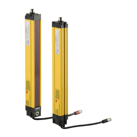
光纤传感器
E3X-ZD系列
使用说明书
非常感谢您使用本产品,使用时请务必遵守以下内容。
·请让具备电气知识的专家实施操作。
·请在阅读并理解本说明书的基础上正确使用。
·请妥善保管本说明书以备随时查用。
*2119107-2B*
(ZD11/ZD41/ZD6/ZD8)
以下项目在确保安全方面非常重要,请务必遵守:
1)请不要在可燃性、爆炸性气体的环境中使用。
2)请不要在有水、油、化学药品残沫处以及有蒸汽影响处
使用。
3)请不要擅自拆卸、修理以及改造本产品。
4)请不要对产品施加超过额定范围的电压和电流。
5)请不要在超出额定范围的环境中使用。
6)请注意电源极性等,以免配线错接。
7)请正确实施负载接线。
8)请不要让负载两端短路。
9)请不要在外壳破损状态下使用。
10)请在废弃时以产业废弃物进行处理。
11)请不要在阳光直射处使用。
12)因为有可能引起火伤,所以因使用条件(周边温度、电
源电压、其他)不同,传感器的表面温度会上升。请在
操作时或清洗时要注意。
安全方面的要点
安全上的注意点
注意
●警告标志的意思
●警告标志显示
如果不正确使用本产品,有可能会引起
轻度、中度人体伤害或者物质性的损害。
可能会引起故障或者火灾。
请在使用时不要超过额定电压。
可能会导致产品破裂。
请绝对不要使用AC电源。
在高温下可能引起火伤。
注意
使用方面的注意点
1)请不要将产品安装在以下场所:
①阳光直射处
②湿度高、可能会结霜处
③有腐蚀性气体处
④对本体有直接振动或冲击影响处
2)电力线、动力线与光电开关使用同一配线管或者配线槽
时,会由于感应引起误动作或者产品损坏,原则上请分
开配线或者使用屏蔽线。
3)导线的延长请使用0.3mm以上的线,并控制在100m以下。
・放大器单元 1台 ・使用说明书(本说明书) 1张
包装内容的确认
1.额定/性能
4)电源投入后,经过200ms以上才可以进行检测。负载与本
产品的电源分开时,请一定要先投入本产品的电源。
5)在切断电源时会发生输出脉冲情况,所以要先切断负载
或负载线的电源。
6)使用连接器型时,为了防止触电或短路,请在不使用的连用
电源端子上贴上保护用贴片(连接器:附属于E3X-CN系列)。
7)放大器装卸或追加时请一定要切断电源。
8)请不要在光纤单元固定于放大器单元的状态下施加拉伸、
压缩产品等动作。
9)请在使用时一定要确保保护罩已盖上。
10)请不要使用香蕉水、汽油、丙酮、灯油类进行清洁。
保护用贴片
连接用电源端子
导线引出式 接插件式
型号 NPN E3X-ZD11 型E3X-ZD6 型
PNP E3X-ZD41 型E3X-ZD8 型
电源电压
外壳
外罩
连接方式
振动(耐久)
材质 聚丁烯对苯二酸盐(PBT)
聚碳酸酯
(PC)
AC1,000V 50/60Hz 1min.
IEC60529规格IP50
(装载保护罩时)
保护构造
20MΩ以上(DC500V)
500m/s
2
X、Y、Z各方向3次
白炽灯:10,000lx 太阳光:20,000lx以下
光同期式(5台)
10~55Hz 上下振幅1.5mm X、Y、Z各方向 2h
动作时:1~3台并列 -25~+55℃(无水汽凝结)
~
4~11台并列 -25~+50
℃(无水汽凝结)
12 16台并列 -25 +45
~℃(无水汽凝结)
保存时:-30~+70℃
动作和保存时:35~85%RH
(无水汽凝结)
动作显示灯、L-ON/D-ON指示灯、示教指示灯(橙色)
7位数码显示(红色) 0~9999
(
光量值)
电源逆接保护、输出短路保护、输出逆接保护
示教(有无工件示教,自动示教),或手动微调
动作·复归:各200μs
集电极开路输出型(因NPN/PNP输出方式的不同而有异)
负载电流50mA以下(残留电压1.5V以下)
L-ON/D-ON 按键切换式
960mW以下(电源电压24V时,消费电流40mA以下;
电源电压12V时,消费电流80mA以下)
光源 (红色4元素LED 620nm)
DC12
~24V±10%
脉动(P-P)
10%以下
(无水汽凝结)
4.各部分的名称和功能
动作显示灯(橙色)
锁定拨杆
5.放大器单元的设置
DIN导轨
1
2
DIN导轨
光纤单元插入部一侧的钩爪
■安装
将光纤单元插入部一侧的钩爪嵌入导轨,
压入直到挂钩完全锁定。
请务必将光纤单元插入部一侧嵌入导轨进
行安装。逆向安装会导致安装强度下降。
■拆卸
压住1方向后,将光纤传感器插入部往2的
方向提。
■并排使用时(接插件式)
最多可连接16台。
1.分别将放大器单元安装到DIN导轨上。
2.滑动放大器单元,插入接插件直到听到“咔”的声音。
因为会有振动等可能导致连接部脱离时,
请使用另售安装配件(PFP-M)进行固定。
请采用相反顺序进行拆卸。
请务必在拆卸放大器单元后再从DIN导轨上拆下。
示教功能按钮
动作模式切换按钮
L-ON/D-ON切换
操作键
门槛值调整
(UP/DOWN)
光量显示灯
针对动作水平显示光量值
2.输入输出电路图
■E3X-ZD11型、E3X-ZD6型(NPN型)
■E3X-ZD41型、E3X-ZD8型(PNP型)
内部回路
负载
DC
12~24V
茶
黒 控制输出
蓝
内部回路 负载
DC
12~24V
茶
黒 控制输出
蓝
3.外形尺寸图
光通信部
10 364.3
38.6 5.3
2.4
4
13
10.7 8
31.5
9.9
10.75
14
5.5
2-φ2.4
7.基本设定
选择入光时ON或者遮光时ON。
可用切换按键设定动作模式。
7.1 动作模式设定
操作说明
(出厂时设定为L-ON)
6.光纤单元的安装
1
2
4
3
1.打开保护罩。
2.打开锁定拨杆。
3.将光纤插入放大器单元插入口并确
保插到底部。
4.将锁定拨杆拨回原来位置固定住光纤。
操作键
L-ON:入光时ON
L/D表示灯:L点灯
D-ON:遮光时ON
L/D表示灯:D点灯
OUT
L
D
TEACH
OUT
L
D
TEACH
OUT
L
D
TEACH
2回交替显示
OUT
L
D
TEACH
OUT
L
D
TEACH
示教指示灯(橙色)
L-ON/D-ON指示灯(橙色)
2回交替显示
OUT
L
D
TEACH
OUT
L
D
TEACH
显示
L-ON→D-ON D-ON→L-ON
12.45
14.35 20.5
18
OUT
L
D
TEACH
(返回受光量表示)
1
1
2
OMRON
PFP-M
OPTICAL FIBER PHOTOELECTRIC
SENSOR
E3X-ZD
Instruction Sheet
Thank you for selecting OMRON product.
Before operating the product, read the sheet thoroughly to
acquire sufficient knowledge of the product.
·Please let the experts operate with electric knowledge.
·Please use the product correctly on the basic of reading
and understanding the instruction sheet.
·Please keep this instruction sheet well for using.
*2119107-2B*
1)Do not use the Amplifier Unit in environments subject to flamm-
able or explosive gases.
2)
Do not use the Amplifier Unit in environments subject to exposu-
re to water, oil, chemicals, etc.
3)
Do not attempt to disassemble, repair, or modify the Amplifier U-
nit in any way.
4)Do not apply voltages or currents that exceed the rated ranges.
5)Do not use the Amplifier Unit in atmospheres or environments th-
at exceed product ratings.
6)Wire the Amplifier Unit correctly, e.g., do not reverse the polarity
of the power supply.
7)Connect the load correctly.
8)Do not short both ends of the load.
9)Do not use the Amplifier Unit if the case is damaged.
10)When disposing of the Amplifier Unit, treat it as industrial waste.
11)
Do not use the sensor in the place exposed to the direct sunlight.
12)The surface temperature of sensor rises depending on the use c-
on
ditions such as ambient temperature and power supply volt-
age. Be careful when you operate or clean it. Hot surface may
cause heat injury.
1)Do not use the Amplifier Unit under the following conditions.
①In the place exposed to the direct sunlight.
②
In the place where humidity is high and condensation may occur.
③I n the place where corrosive gas exists.
④In the place where vibration or shock is directly transmitted to
the product.
2)Wire the Amplifier Unit separately from power supply or high-
voltage lines.If the Amplifier Unit wiring is wired together with or
placed in the same duct as high-power lines, inductive noise may
cause operating errors or damage the Amplifier Unit.
3)Do not extend the cable to more than 100 m, and use a wire si-
ze of 0.3 mm² or larger for the extension cable.
4)
The Amplifier Unit is ready to operate 200 ms after the power su-
pply is turned ON. If the Amplifier Unit and load are connected to
power supplies separately, turn ON the power supply to the Amp-
lifier Unit first.
5)
Output pulses may occur when the power is interrupted, so
turn OFF the power to the load or load line before turning OFF
the power to the Sensor.
6)When you use the Amplifier Units with Connectors,to prevent el-
ectric shock or short-circuits, attach the protector seals (pro-
vided with E3X-CN-series) .Connectors to the sides of power
supply connectors that are not being used.
7)Always turn OFF the power supply before connecting, separating,
or adding Amplifier Units.
8)Do not pull or apply excessive pressure or force (exceeding 9.8 N·m)
on the Fiber Unit when it is mounted to the Amplifier Unit.
9)Always keep the protective cover in place when using the Ampli
f
-
ier Unit.
10)Do not use thinners, benzine, acetone, or kerosene for cleaning
the Amplifier Unit.
Power supply connector
Protector seal
Precautions for Safe Use
Precautions for Correct Use
Precaution on Safety
CAUTION
●Meanings of Signal Words
●Alert statements in this Manual
Indicates a potentially hazardous situation
which, if not avoided, may result in minor or
moderate injury or in property damage.
Do not use it exceeding the rated voltage.
There is a possibility of failure and fire.
Do not connect sensor to AC power supply.
Risk of explosion.
Hot surface may cause heat injury.
CAUTION
1.Specifications
Pre-Wired Separate connector
NPN
E3X-ZD11 E3X-ZD6
PNP
E3X-ZD41 E3X-ZD8
Case
Cover
Materials
Polybutylene terephthalate (PBT)
Polycarbonate (PC)
Shock resistance Destruction: 500 m/s², for 3 times each in X, Y and Z
directions
Degree of protection IEC 60529 IP50 (with Protective Cover attached)
Dielectric strength 1,000 VAC at 50/60 Hz for 1 minute
Vibration resistance
Destruction: 10 to 55 Hz with a 1.5mm double amplitude for
2 hours each in X, Y and Z directions
Ambient humidity
Operating and storage: 35% to 85% (with no condensation)
Insulation resistance 20 MΩmin. (at 500 VDC)
Ambient illumination Incandescent lamp:10,000lx max.Sunlight:20,000lx max.
Ambient temperature
Operating:Groups of 1 to 3 Amplifiers: −25°C to 55°C
Groups of 4 to 11 Amplifiers: −25°C to 50°C
Groups of 12 to 16 Amplifiers: −25°C to 45°C
Storage: −30°C to 70°C (with no icing or condensation)
Digital display 7 segment digital display(red), 0~9999(Light power)
Interference prevention
light parallel(5sets)
Protection circuits
Power reverse protect, Output reverse protect, Output-short
protect
Indicator Operation,L-ON/D-ON, Teaching indicator(orange)
Threshold setting Teaching(With/without workpiece teaching,Automatic
teaching), or manual adjustment
Control output Open collector: max. 50mA;
residual voltage: max. 1.5V;L-ON/D-ON button alter
Response time 200μs max
12 to 24 VDC±10%, ripple(p-p) 10% max.
Power consumption
Power supply voltage
960mW max.(current consumption:40mA max. at power
supply voltage of 24VDC;current consumption:80mA max.
at power supply voltage of 12VDC)
Connection method
Model
Light source Red AIGaInN LED(620nm)
(ZD11/ZD41/ZD6/ZD8)
8.门槛值设定
在工作状态下用UP/DOWN键进行设定,
通过数码显示确认门槛值。
显示 说明操作键
可以采用按键微调方式设定门槛值。
8.1 门槛值调整
OUT
L
D
TEACH
OUT
L
D
TEACH
5回交替显示
显示操作键
OUT
TEACH
OUT
TEACH
OUT
TEACH
OUT
TEACH
OUT
TEACH
OUT
TEACH
OUT
TEACH
分别检出工件有和无2点,然后将动作水平设定在中间点。
8.2 工件有无的示教(快速调整)
OUT
L
D
TEACH
OUT
L
D
TEACH
OUT
L
D
TEACH
OUT
L
D
TEACH
OUT
L
D
TEACH
OUT
L
D
TEACH
OUT
L
D
TEACH
OUT
L
D
TEACH
OUT
L
D
TEACH
OUT
L
D
TEACH
OUT
L
D
TEACH
OUT
L
D
TEACH
说明 说明
显示
A
A
交替显示1回
在有工件的
状态下,按下
Teach键,进
入示教模式
按住3秒以内
进入2点示教
模式
交替显示2回
交替显示5回
在工件无的
状态下,按下
Teach键,完
成2点示教
交替显示1回
显示第1点
示教结果
显示第2点
示教结果
显示2点示教
后最终设定
的门槛值
交替显示1回
交替显示1回
按下UP或DOWN键,
可显示当前的门槛值;
门槛值标记与门槛值
交替显示5回后,
回复到正常显示
光量值的界面状态。
按下UP键,
增加门槛值;
按下DOWN键,
降低门槛值;
※通过长按可
改变数字
增加速度。
增加门槛值 减小门槛值
闪烁 闪烁
(返回受光量
表示)
2回交替显示
10.错误显示
发生各种错误的时候,会显示以下信息。请参考以下内容进行处置。
9.便利的功能
使用时的承诺事项
①为了确保安全,请勿将本产品直接或间接用于人体检测。需要使用该用途时,请选用
本公司传感器综合样本中刊登的安全传感器。
②使用于下列用途时,请与本公司营业担当商谈、并根据规格书等确认后,采用相对于
额定性能留有一定余裕度的使用方法或者采取即使出现故障也能使危险度降低到最小
的安全电路的对策。
a)屋外使用、用于有潜在的化学污染或者有电气妨害时,或者是产品手册、使用说明书
等没有记载的条件或环境中使用时
b)用于原子能控制设备、焚烧设备、铁路·航空·车辆设备、医疗设备、娱乐器械、安
全装置以及按照行政机关或个别业界规定制造的设备时
c)用于可能危及生命、财产的系统·机械·装置时
d)用于煤气、水道、电力供给系统或者24小时连续运转系统等的高可靠性设备时
e)用于其他,以上述a) d)为基准,需要高度安全性的用途时
*上述内容是适用条件的一部分。请参阅本公司综合产品手册·数据等最新版商品目录、
手册中记载的保证·免责事项内容后再使用。
■ 制造商
欧姆龙(上海)有限公司
地址:中国上海市浦东新区金桥出口加工区金吉路789号
电话:(86)21-5050-9988
■ 技术咨询
欧姆龙(中国)有限公司
地址:中国上海市浦东新区银城中路200号中银大厦2211室
电话:(86)21-5037-2222
技术咨询热线:800-820-4535
网址:http://www.fa.omron.com.cn
OMRON Corporation
~
OUT
L
D
TEACH
OUT
L
D
TEACH
显示
操作键
检测规定时间内的变化,将动作水平设定在最大和最小的中间点。
此方法最适合用于对工业流水线上连续移动工件进行检出的场合。
8.3 自动示教(快速调整)
OUT
L
D
TEACH
OUT
L
D
TEACH
OUT
L
D
TEACH
OUT
L
D
TEACH
OUT
L
D
TEACH
OUT
L
D
TEACH
OUT
L
D
TEACH
OUT
L
D
TEACH
OUT
L
D
TEACH
OUT
L
D
TEACH
OUT
L
D
TEACH
OUT
L
D
TEACH
交替显示2回
OUT
L
D
TEACH
OUT
L
D
TEACH
交替显示2回
OUT
L
D
TEACH
OUT
L
D
TEACH
交替显示2回
B
B
OUT
L
D
TEACH
说明 说明显示
交替显示3回
Teach键长按
并保持3秒以
上。等出现
Auto字母显示
后,使检出物
通过。放开
Teach键,自动
示教完成。
交替显示1回
交替显示1回
交替显示1回
交替显示1回
显示最小阈值
显示最大阈值
显示自动示教
后最终设定的
阈值
(返回受光量
表示)
OVER错误
受光量过大。因为已将门槛值设定为最小灵敏度,
所以要在确认动作状态后再使用。根据需要,请在
重新改善光纤单元的设置后再次实施示教。
LOW错误
受光量过小。因为已将门槛值设定为最大灵敏度,
所以要在确认动作状态后再使用。根据需要,请在
重新改善光纤单元的设置后再次实施示教。
NEAR错误
变化过小。因为存在着不恰当的动作的可能性,
所以请在确认动作状态后再使用。
OUT
L
D
TEACH
闪烁2回
OUT
L
D
TEACH
闪烁2回
数据错误
闪烁存储数据错误。
重新示教,调整门槛值等。
过电流错误
在控制输出中有过电流流动。
请确认负载是否合适、有没有短路。
说明
操作键
同时按下UP键
和DOWN键
(5秒以上)
按下UP键或DOWN键
切换至显示YES?。
按下TEACH键,若显示
good则表示产品回复
到工场出荷时的状态。
OUT
L
D
OUT
L
D
OUT
L
D
OUT
L
D
TEACH
OUT
L
D
显示
显示3秒
TEACH
TEACH
TEACH
TEACH
(若显示no?时按下TEACH键,则返回
到设定初始化前的光量显示模式。)
进行商品初始化设定,可使商品回复到出场时的设置。
9.1 商品初始化设定
2. I/O Circuit Diagram
■
E3X-ZD11,E3X-ZD6(NPN )
■
E3X-ZD41,E3X-ZD8(PNP )
3.Dimensions
Optical
communication position
10 364.3
38.6 5.3
2.4
4
13
10.7 8
31.5
9.9
10.75
14
5.5
2-φ2.4
DC
12~24V
Brown
Black control output
Blue
Load
Main Circuit
DC
12~24V
Brown
Black control output
Blue
Load
Main Circuit
12.45
14.35 20.5
18
4.Nomenclature
Operation
Indicator(orange)
Lock lever
Operation mode Selector
L-ON/D-ON
TEACH function button
set key
set sensitivity
(UP/DOWN)
Light level Indicator
Display the relative value
Teaching
Indicator(orange)
L-ON/D-ON
Indicator(orange)
5.Installing the Amplifier Unit
DIN Track
1
2
DIN Track
Hook on the Fiber Unit connector end
■Mounting Units
Catch the hook on the Fiber Unit connector end of the
Unit on the DIN Track and then press down on the
other end of the Unit until it locks into place.
Always TEACHach the Fiber Unit connector end first.
If the incorrect end is TEACHached first, the
mounting strength will be reduced.
■Removing Units
Press the Unit in the direction indicated by "1"
and then lift up on the Fiber Unit connector end
of the Unit in the direction indicated by "2."
Manufacturer:
Omron Corporation,
Shiokoji Horikawa, Shimogyo-ku,
Kyoto 600-8530 JAPAN
Shanghai Factory
No.789 Jinji Road,
Jinqiao Export Processing District,
Pudong New Area,Shanghai,201206 CHINA
TRACEABILITY INFORMATION:
Representative in EU:
Omron Europe B.V.
Wegalaan 67-69
2132 JD Hoofddorp,
The Netherlands
The following notice applies only to products that carry the CE mark:
Notice:
This is a class A product. In residential areas it may cause radio
interference,in which case the user may be required to take adequate
measures to reduce interference.
