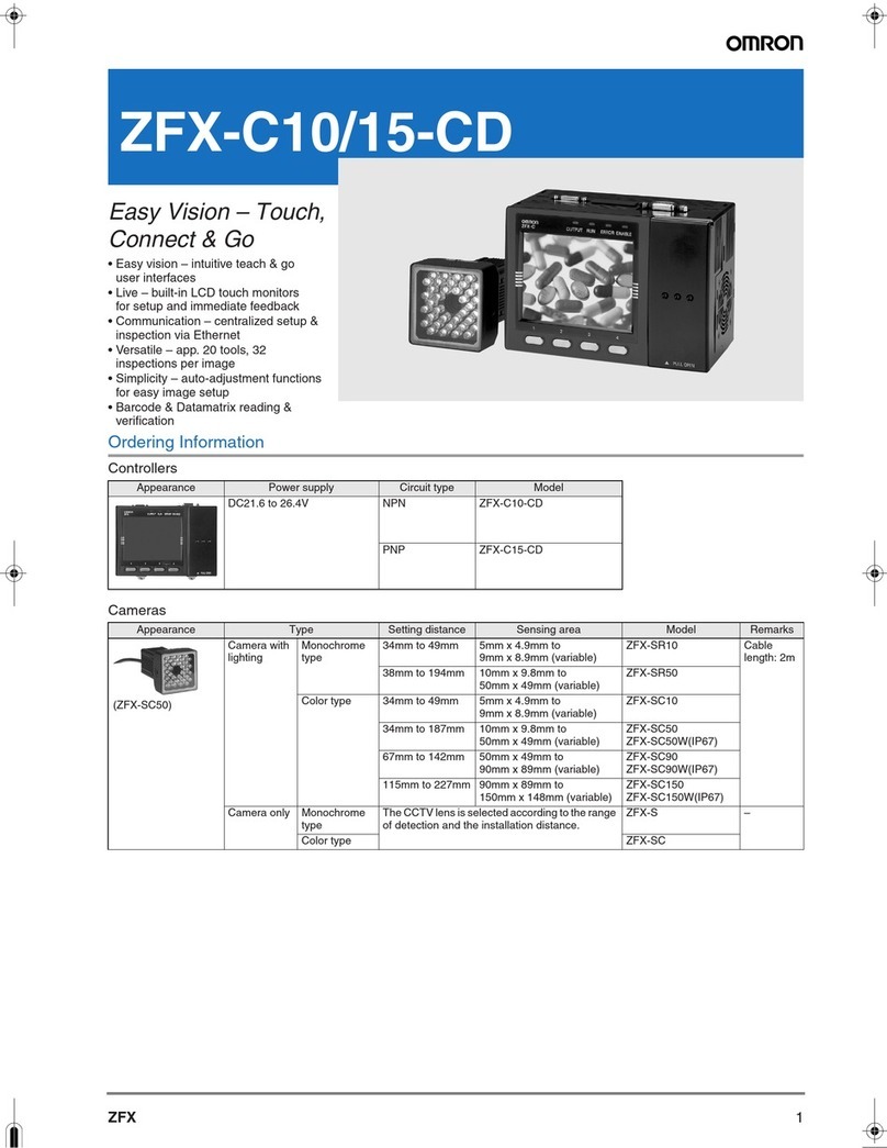
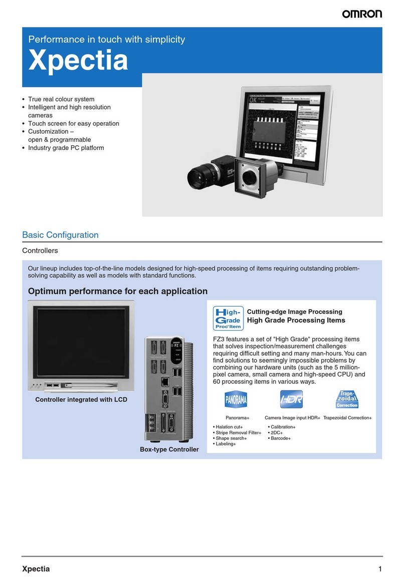
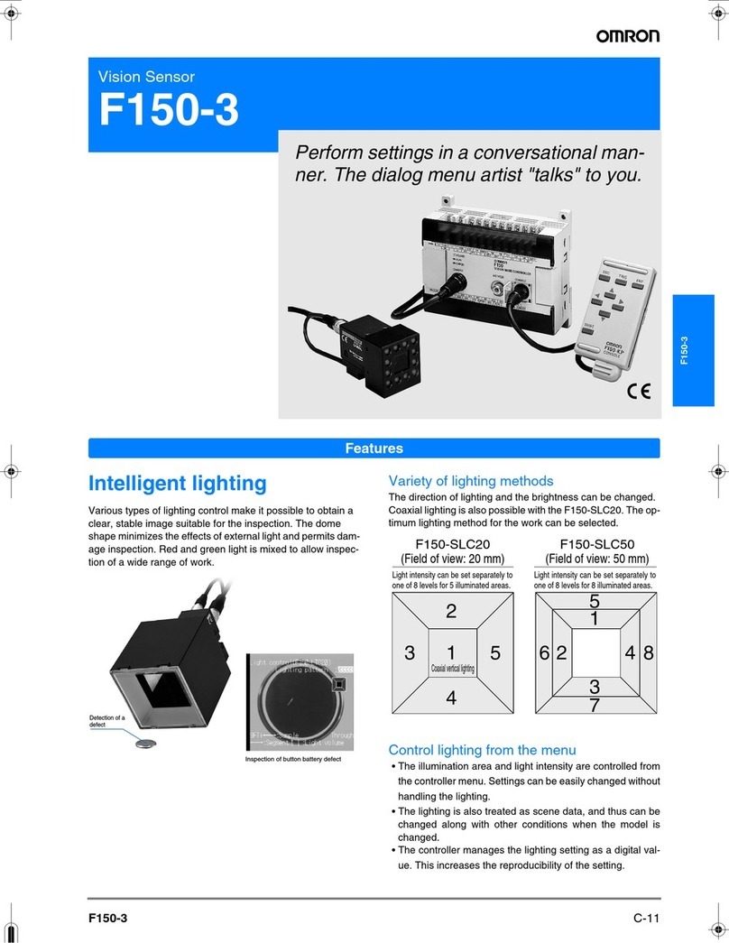
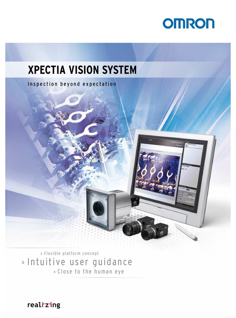
Omron EZ3-900 Series User manual


22

33

4
Industry's fastest
Only Possible with Multi-task System
The FZ3-900 series is equipped with Dual Mega ARCS Engines
to process data twice as fast as when one Mega ARCS Engine is
used. This engine achieves multi-task, high-speed processing not
heretofore possible.
With conventional serial systems, each process can not be started
until the previous process is completed.Under the Dual Mega ARCS
architecture, two engines perform multiple tasks in parallel to
dramatically reduce the inspection time.As a result, you can process
more data over a shorter time compared to conventional systems.
Dual Mega ARCS Engines
Only the Dual Mega ARCS architecture can realize a completely
parallel processing of measurement, adjustment and logging tasks!
The key feature of Dual Mega ARCS Engines is that they enable completely
parallel processing.Parallelprocessingnotonlyspeedsupinspection,
butitalsoallowsthesystemtobehavelikehavingtwobrains(heads)
bylettingyouinspecttwocompletelydifferentlineswithasingle
visionsensororadjustparametersduringinspection.
Short for "Advanced Real Color Sensing," ARCS is OMRON's patented imaging engine capable
of processing images in real colors. The FZ3 series real color processing captures and quickly
processes vast amounts of color information to achieve ideal sensing close to what human eyes
can. It realizes accurate, stable inspection unthinkable with simple filtering. The ARCS processing
capability continues to advance with the progress of the FZ series.
P. 5 Real Color Sensing
What is ARCS?
Measurement
Measurement
Processing 2 Processing 3Processing 1
Processing 3 Processing 5Processing 1
Processing 4 Processing 6Processing 2
[Conventional processing]
[Dual processing]
Measurement
Measurement
Measurement
Adjustment
Perfect for applications requiring inspection speed
[1] High speed mode (parallel operation)
One measurement ow is divided into two to process the two sub-ows in parallel P. 5
[2] High speed mode (single line)
The conventional multi-input function has been improved to achieve even shorter
trigger input intervals P. 5
Two different inspections with a single unit
[3] Multi-line random-trigger mode
Two measurement flows can be processed independently P. 6
Adjusting and checking settings without stopping production operation
[5] Non-stop adjustment mode
You can adjust flows and setting parameters during measurement P. 7
Saving all inspection images
[4] High speed logging mode
Measured images can be saved to an external memory device without affecting the
measurement time P. 6
Dual processing of
<measurement x measurement>
Dual processing of
<measurement x adjustment>
Dual processing of
<measurement x logging>
Industry's Fastest Inspection & Measurement Processing
[ Patent Pending ]
Industry's
fastest CPU
Dual Mega ARCS
P.B.S.
architecture
Measurement
Logging

5
Fastest measurement Highspeed mode (parallel operation)
Short trigger intervals High speed mode (single line)
Multiple measurements are processed in parallel with the system making decisions automatically to minimize the total
measurement processing time from image input to result output. This significantly reduces the time to output result following
a trigger input. This feature is ideal for inspections where more data must be processed or higher resolution is needed.
OMRON's unique multi-input function has become more advanced. Combined with the parallel processing capability
of Dual Mega ARCS Engines, this function halved the trigger intervals of conventional systems. You can add inspection
items without affecting the current processing time, which gives you scalability to meet future needs.
[Conventional flow]
[Flow in high speed mode]
0. Camera
image input 1. Search 2. Search 5.
Scratch
and soiling
6.
Number
of edges
7. Area
gravity
center
4. Labeling
3. Position
compensation
0. Camera
image input
1. Search
2. Search
4. Labeling
5.
Scratch
and soiling
6.
Number
of edges
7. Area
gravity
center
3. Position
compensation
1st
1st 2nd 3rd 4th
2nd 3rd
With multi-input
Without multi-input
Image capture
Image capture
Measurement
processing
Measurement
processing
Trigger
Standby Standby
1st 3rd 5th
2nd 4th 6th
1st 2nd
1st 2nd
3rd
1st 2nd 3rd 4th 5th 6th 7th
Image capture
Measurement
process 1
Measurement
process 2
Camera images can also be captured during measurement.
If image inputs exceed the buffer capacity, however,
trigger intervals cannot be shortened because the minimum
trigger interval depends on the measurement processing
time.
Parallel measurement processing halves the trigger
intervals of conventional systems. As a result, the
inspection tact time is also reduced to a half.
CCD alignment inspection
rA shorter tact time can be achieved after consolidating
lines or when the utilization ratio is to be improved at
subsequent production increases.
rAlignment data and other measurement results can be
sent to subsequent processes more quickly.
Parallel measurement flows significantly reduce
the measurement time. This function is particularly
useful in inspections using high-pixel camera that
otherwise take a long measurement time.
Effect
Issues
Resolution
[Conventional system]
[
High speed mode
]
(Example) The flow
shown below reduces the
processing time by 47%
Camera image input
ECM search
ECM search
Line regression
Line regression
Operation
Appearance inspection of caps
Shorter trigger intervals shorten the inspection cycle time.
The processing flows for first and second
triggers are processed in parallel to halve the
trigger interval.
Signicantly
shorter
processing time!
Trigger intervals have
been halved!
Color gray filter
Shape search+
Processing before
measurement
Position compensation
Background trimming
Processing before
measurement
Color gray filter
Fine matching
Camera image input
Effect
(Example) The flow shown below halves the
trigger intervals of conventional system to only
26 ms.

6
Benet of a Multi-task System
Conventional imaging systems cannot perform two inspection processing simultaneously. With Dual Mega
ARCS Engines, one controller accepts two trigger inputs simultaneously or randomly to process two different
setups parallely or independently.
Complete parallel processing of measurement and logging means you can also connect high-speed, large-
capacity (up to 2 terabytes) hard disk drives. Accordingly, you can save all images on high-speed tact lines,
which was difficult to do with conventional systems (*1).
One unit performs inspections that normally require two units Multi-line random trigger mode
All images can be saved even during measurement High speed logging mode
Printing inspection in
automobile assembly
processes
Defect inspection on a new
product or a line adopting a
new manufacturing method
All images you have saved can be utilized for
trend analysis to help establish an appropriate
manufacturing method quickly for a new product
or a line adopting a new manufacturing method.
r
When a NG occurs, the cause can be identified and
remedial actions taken quickly.
r
Saving all images leads to more efficient traceability control.
Before, two controllers were needed to inspect two locations,
processes or lines within the required tact time, which added
to introduction cost.
With the FZ3-900 series, on the other hand, two triggers
can be input randomly to run two independent inspection
processing in parallel.
Since logging was not possible during measurement, the user
had to choose either measurement or logging. Accordingly,
not all images could be saved or image input triggers had to
be delayed depending on the measurement trigger intervals.
Measurement and image logging are processed completely in
parallel. As a result, you can save all images.
Image input 1 Image input 2 Image input 3
Priority on image logging
Priority on measurement processing
Image input
Image input
Image logging
Measurement
processing
Measurement
processing
Image
logging 1
Measurement
processing
Measurement
processing
Interruption
Image input 1 Image input 2 Image input 3
Image input
Measurement
processing
Measurement
processing
Image logging 1 Image logging 2
Measurement
processing
Measurement
processing
The next image input is delayed
Image input 1 Image input 2
Measurement
processing
Image logging 1
All you need
is one unit
[Conventional system]
[High speed logging]
All images are saved.
*1 All imagescan be saved under the following conditions:
r300,000-pixel camera x 1 unit . Measurement time: 33 ms
rImagescan be saved continuously for approx. one week when a 2-terabyte
HDD isused (based on 8 hoursof operation a day).
Introduction
cost
Installation
space Halved!
Simultaneous inspection of two
locations
This mode is ideal for applications where triggers
are not input simultaneously or constantly, such
as when the top surface is inspected with a single
trigger and side faces with four triggers.
You can reduce the number of controllers to be installed
to save installation space, introduction cost and current
consumption.
Random inspection of lines
positioned close to each other
Even when the timing of work arrival
is not at constant intervals, they can be
inspected with only one controller.
Effect
Effect
Issues
Resolution
Resolution
Reduce the time and cost for setup and operation
Issues

7
Doubly effective when combined with the Non-stop adjustment mode NG analyzer
Zero downtime for setting adjustment Non-stop adjustment mode
You can check conditions and reconfigure settings while measurement is still in progress if dimensional
variations of works, changes in external environment, etc., require adjustments and checks. Since adjustment
is possible without stopping the line/inspection, you can eliminate downtime, need to add visual inspections
to identify uninspected products, and cost increase associated with them.
You can display in a structured manner a graph showing the results measured at once on logging images. This
lets you identify the cause of a given NG much more quickly. You can also measure all images again after
changing a given setting, to check the reliability of the new setting.Adjustment and troubleshooting has never
been so quick, simple and reliable.
Loss cost can be reduced. Ideal for
mass-production processes with a higher
unit production volume or 24-hour lines. r3FTVMUTDBOCFDIFDLFEBOEBEKVTUNFOUDBOCFNBEFXJUI
zero downtime.
r#FDBVTFUIFMJOFJTOPUTUPQQFEUIFSFJTMFTTJEMFUJNF
associated with restarting of the line.
Processed items and parameters that
generated an erroneous judgment can be
identified at a glance.
You can check the detailed results of
parameters to identify the cause of the NG.
Printing / soiling inspection of sheets
Downtime
Loss cost
Zero
Select a desired measurement result on the
graph to switch to the adjustment mode.
Effect
Identify the cause and adjust the settings.
Apply the
new settings.
Continuous inspection
without stopping line
operation
Change thesettings.
A NG occurs.
Measure again in a trial
run to conrm the
settings.
Parallel processing of inspection
and adjustment
Check saved images to
identify the cause.
NG analyzer

8
Original HDR Technology
Eliminate the side effects of lighting
FZ3's high dynamic range minimizes the effects of lighting such as halation and allows highly precise
inspections.
Reflective and shadowy areas can be
reproduced simultaneously under the same
lighting conditions.
The reective surfaces of cylindrically-curved
workpieces in which conventional vision
sensors have had difficulty can be reproduced.
The surfaces of metal workpieces can be
reproduced accurately.
Conventional images
HDR image
The inuence of changing lighting conditions
from day to night are effectively minimized.
Conventional images
HDR image
Night Night
Day Day
Conventional images HDR image
Any spot outside the dynamic range is blurred by halation
or shadow.
Defects Detectable Even on Reective or Shadowy Surfaces
Defects Undetectable Due to Overexposure or Underexposure
The surface of the workpiece is accurately reproduced and
detected even with overexposure or underexposure.
Dynamic
range
after HDR
processing
Dynamic range
of the upper
image
Dynamic range
of the lower
image
Underexposure
Halation
High Dynamic Range Function
Conventional images
HDR image
Conventional images
HDR image
Making it possible!

9
HDR Image Generation Technology
Dynamic range means the imaging hardware's ability to manage differences in lighting. The higher dynamic range the hardware
scores, the clearer images it can generate when imaging objects with a strong contrast in luminosity. Featuring the HDR Image
Generation technology, FZ3 can take two or more images of a workpiece at different levels of luminosity by automatically changing
its shutter speed and synthesizes them into a single image rapidly. As a result, the bright field where image capture is possible
expands 5,000 times in LD ratio compared to a general CCD camera. Accordingly, you can obtain vivid images not possible in
processing flows where images are color-depth filtered one by one in real time.
Luminosity
distribution
histogram
Instantaneously calculates the
luminosity distribution in the field
of view, and automatically setting a
number of images to be taken and the
shutter speed for each image.
Continuous imaging at different shutter speeds. Inst an taneous synth esis of dif fe re nt
images at different levels of luminosity.
The wide dynamic range allows you
to generate clear images even with
overexposure or under changing lighting
conditions.
1st image
high speed
2nd image
medium speed
3rd image
low speed
Luminosity
HDR High-Contrast Mode
There is a low contrast in brightness between the background noises and the thing to be
inspected.
The contrast is enhanced by integrating and enlarging two or
more images.
Luminosity Luminosity
Integration
Enlargement
Technology of HDR High-Contrast Mode
The HDR function that quickly produces multiple composite images offers the high-contrast mode. In this mode, images captured
at a constant shutter speed are layered on top of one another and output. Before, each image had to be enlarged to increase
contrast, and consequently the noise component of the image was also amplified. In the HDR high-contrast mode, on the other
hand, multiple images are combined together and then averaged to reduce their noise component, after which the images are
enlarged. This way, only the contrast of the area of interest and its background can be increased.
Conventional system
Low contrast makes the surface appear uniform.
HDR high-contrast image
Many scratches and soiled areas can be found.
++

10
High Resolution Image Generation
Higher Resolutions and Wider Fields of Vision
The new 5 million-pixel cameras allow high precision appearance inspections and measurements that cannot be
handled by conventional 2 million-pixel cameras.
Making Invisible Defects VisibleReducing Set-up Time
Thanks to the
cameras' wider fields
of vision, you don't
have to move their
positions during set
up on a production
line for different
products in different
sizes.
The improved
resolution of the
system's cameras
allows you to detect
very slight defects
that were impossible
for its predecessor to
catch.
5million pixels2million pixels
Color Type
FZ-SC5M
Black and
White Type
FZ-S5M
5million pixels
(2448×2044 pixels)
2million pixels
(1600×1200 pixels)
1.5-times wider eld of vision Reducing Tact Time
Even a large
workpiece can be
imaged at one time
and the details are
very clear
FZ3 takes a single
wide-view image of a
large workpiece used
be imaged in multiple
pieces and thus
reduces inspection
tact time.
2044
300,000
pixels
2 milion
pixels
2448
A lineup of high-accuracy lenses is available to fully utilize the high-resolution camera of 5 million pixels or
more and thereby realize accurate inspection. The resulting greater contrast and higher resolution ensure accurate
positioning check, scratch inspection and other inspection applications where higher accuracy is required.
* Please contact your OMRON sales representative.
Normal high-resolution lens
Only 5 lines can be detected.
Lens of over 5 mega pixels
All 9 lines are detected.
High measurement accuracy Lens of over 5 mega pixels
5 Million-Pixel Cameras
5 milion pixels

11
Autofocus Camera / Intelligent Camera with illumination
Autofocus Camera
FZ-SZC100
FZ-SZC15
Intelligent Camera
FZ-SLC100
FZ-SLC15
Color Color
These image processing cameras for FA needs
are equipped with auto focus functions and lights.
You can remotely control the focus, aperture, field
of vision and lighting of the cameras installed at
a distant from the controllers. You can apply a set
of lighting conditions for any particular inspection
to different lines by saving the setting data for the
inspection into the controller. This function allows
prompt setting for each inspection procedure.
It also helps reduce setting variations among
individual operators.
Innovative zoom function
With this function, the camera can exibly respond to inspections
on mixed production lines or any changes in its eld of vision for
additional inspections.
Setting the focus, aperture
and eld of vision
Intelligent Lighting
You can control the brightness levels of up to 8 lights in 256 gradations.
Since you can register the most appropriate setting for each lighting task,
stable lighting conditions are always ensured.
* Function available only with FZ-SLC100 and FZ-SLC15
Our high-performance, high-speed 300,000-pixel cameras
have been remarkably downsized. They can be installed in
spaces which are too small for conventional cameras.
Most compact and
shortest pen-shaped
camera in the Industry
First slim at camera in the
Industry
Suitable for use in narrow
spaces
Suitable for use in spaces with
little depth that usually require
mirrors
*This is the size with nothing other than a lens
(FZ-LES3) and does not include a spacer for
installation.
22mm
Approx.
32 mm*
Color Color
Color
Black & White Black & White
Black & White
FZ-SPC
FZ-SP
FZ-SFC
FZ-SF
12mm
18mm
*This is the size with nothing other
than a lens (FZ-LES3).
Approx. 59 mm *
Ultra-compact Pen-shaped Camera / Ultra-slim Flat Camera
This high-resolution 2-million-pixel camera
(1600 × 1200 pixels) boasts the fastest image
capture speed in its class. It is equivalent
to the speed of 300,000-pixel cameras.
Furthermore, the camera can capture 1-million-
pixel images (1600 × 600 pixels) at a speed of
60 fps in the partial capture mode.
2-million-Pixel camera
Color
Black & White
FZ-SC2M
FZ-S2M
High speed image capturing of 30 fps
60fps(16ms)
15fps(66.6ms)
30fps(33.3ms)
Ordinary 2-million-pixel
camera
2-million-pixel camera
of FZ3 Series
Partial capture of
1-million-pixel images
This camera achieves an image
capture speed of 80 fps with full VGA
resolution of 640 × 480 pixels, saving
input time about 4 ms. It features high
speed with highest cost performance.
Furthermore, it allows faster image
capturing in the partial capture mode.
FZ-SC
FZ-S
High speed image capturing of 80 fps
80fps(12.5ms)
Ultra-high-speed
Camera of FZ3 Series
(Resolution: 640 × 480)
60fps(16.7ms)
Ordinary double speed
camera
(Resolution: 512 × 480)
Partial capture function
This function allows you to specify any
part of the workpiece and capture images
thereof at a faster speed.Image capturing
at a speed of 3 ms maximum is possible.
300,000-pixel Camera
Small Size for Easy Installation
No Additional Power Supply Needed
Simple System With Simple Wiring
Controlling Lighting from the Controller
The controller can
prevent mutual
interference between
different cameras by
controlling lighting.
The strobe controller
installed on a robot
is ideal for robotic
inspections.
Data of specific lighting
conditions can be saved in
the controller. In this way,
you can save time for setting
lighting conditions before
conducting each inspection.
Application Examples
You can easily control lighting by connecting this strobe controller to the camera and the light using a single cable.
Unlike ordinary lighting control units built on controllers, you do not need any complex wiring for this strobe
controller. This makes the system very easy to handle. You can control all lighting sequences with this controller.
Strobe Controller to manage the Lighting Without Complex Wiring and Additional Power Supply
Controller
Camera Cables
LED lights
Camera
Strobe controller
108mm
Model with Wide Field of Vision
Model with Narrow Field of Vision
Approx.
15 mm Approx. 3 mm
Approx. 70 to 197 mm
Approx. 35 to 67 mm
100mm 13mm
Lighting Patterns
8 places can be controlled
Brightness Levels
256 gradations

12
Real-time Image Generation Technology
Correcting distorted images shot from an angle. High-precision inspections are ensured even when images are
taken from an angle or the carrying process is unstable.
Wide Panorama
Images taken by two to four 2-million-pixel
cameras are put together like a line camera to
generate a single image as if it is taken by a
single camera when inspecting a horizontally
long workpiece.
Synthesis of up to four images
Up to four images can be synthesized
horizontally and vertically in accordance with
the shape of the workpiece.
Camera Image 1
An inspection area can be
specied across the images taken
by two or more cameras.
The position of the inspection
area can be adjusted based on
the overview image.
Camera Image 2 Camera Image 3 Camera Image 4
5200 pixels *2
The position of the
workpiece is
measured based on the
overview image.
Camera Image 1
Camera Image 2
Camera Image 3
Camera Image 4
Precise Inspections of Large Workpieces in Whole
When taking images of a large workpiece in multiple pieces using two or more cameras, a conventional vision
sensor processes the images taken by the cameras separately in order to secure a satisfactory level of resolution.
FZ3's panoramic image processing*1capability allows the measurement of a large or long workpiece in whole
by synthesizing the images taken by camera and generating a single image from them.
[ Patent Pending ]
Cross shots image capture
is possible
FZ3 allows space-saving line designs
since cameras can be mounted
in any small spaces at any angle.
Furthermore, you would have no
difficulty in finding appropriate
spaces for an additional camera for
an additional inspection item.
Coping with any flutter in
the carrying process
High-precision inspections are
ensured even when there is flutter
in the carrying process. Unlike the
conventional vision sensors, FZ3 can
also correct perspective distortions.
Not only the
horizontal and
vertical positions,
but also the
inclination can be
compensated.
Even when the subject inclines
due to the movement of the arm,
its position can be compensated.
Minimizing the effects of the camera position or flutter during the carrying process
[ Patent Pending ]
Registered model image [Conventional system]
Scroll of the subject reduces the
correlation value. The model cannot be
detected.
[After trapezoidal distortion correction]
Even when scroll occurs, the distortion is
compensated to make sure the model is
detected stably.
Scroll
OKNG
Ideal for Inspection
Trapezoidal Distortion Correction
Ultra-Wide Panorama Image Processing
*1 This feature can be performed with cameras of 2 million pixels or less.
*2 The images of four 2 million-pixel cameras overlap each other at their
edges, with each overlapping area covering 25% of the entire area of each
image.

13
Before processing After processing
Eliminating reflection of light on the surfaces of moving workpieces
This feature detects blurs caused by
halation or unstable lighting, and
automatically make corrections.
It is very useful when workpieces to be
inspected are moving at a high speed
or inspections are made through a
transparent film.
Analyzing images by subtraction and detecting only subtle changes as defects.
The lter removes fringes in the background and detects defects only even when fringes is as big as defects.
Before processing Before processingAfter processing After processing
Conventional images Image processed by the Fringe-killer Filter
FZ3 can choose the type of fringes to be removed in accordance with the
background of each workpiece to be inspected.
Removing horizontal, vertical and lattice fringes
Removing fringes to detect defects
Other than detecting defects by
subtraction, FZ3 can also remove
some peculiar patterns such as fringes
in the background for more stable
inspections.
Analyzing the color elements captured as
specular light (halation)
Automatically choosing the most appropriate
filter to prevent halation and generating
images most appropriate for inspections
[ Patent Pending ]
Halation is cut off by capturing
images using a special halation-
cutoff lamp (FZ-SXCRB7018BR-
4S).
High-speed Halation Prevention Filter
Fringe-killer Filter

14
New generation processing items (approx. 60)
Filters to optimize input images / Position Correction
You can easily and
immediately eliminate color
shading just choose a
specic color on the screen.
Color extracting lter
The lter allows the extraction of any specic color from the image. Since you can register up to eight colors, as the colors to be
eliminated, you do not need to adjust settings for different processing items. The lter works in two modes, one for extracting the color
specied and the other for extracting all colors other than the specied one. You can exibly switch between the two modes according
to requirements for individual inspections.
You can easily specify any color by just clicking it on the screen.
The color chart on the screen, that shows the color you have
chosen, enables intuitive operation even for fine adjustments.
Up to eight colors can be
registers.
Elimination of Background
A minimum value and a maximum value are set for each of the RGB colors. Any color depth under the minimum value is specied as "0,"
and any depth over the maximum value as "255." Then all other depths between them are stretched into a 0 to 255 scale. An area to be
inspected is visualized with high contrast while the effects of depths outside this scale are eliminated.
Rectangular Development of Circular Images
Before processing After processing
255
255
0
0
Maximum
value
Minimum
value
Finding minimum and maximum
values of color depth
Cutting any depth outside
this scale
Stretching all other depths into
the scale and eliminating the
effects of depth variation
Before processing After processing
Extracting pink and yellow green
All colors other than the ones specified can be
extracted. When there are a number of colors you want to extract,
this mode saves time in color setting.
First in the industry
Color shadings elimination lter
The filter eliminates Specific background color data that may hamper the detection of defects. It also improves the accuracy of
inspection to detect scratches or dirt. This cutting-edge function is made possible only with FZ3's Real Color Sensing technology.
This function allows recognition of characters printed along the
circumferences of circular surfaces by converting circular images
into rectangular forms. The characters can be inspected with the
same resolution even after such rectangular development.

15
Inspections of Scratches and Dirt
Subtle scratches and dirt can be detected with more fine-tuned
conditions compared to conventional inspections.
Since you can clearly distinguish defects to be detected from the
background, the failure detection rate can be decreased.Combined
with our 5 million-pixel camera, this function enables much more
precise inspections of scratches.
Color images taken by the camera are
processed after being converted into black
and white pixels. The color extracted is
represented as white, and the other colors as
black. Based on minimum information, high
speed processing is possible. Since color
data is limited only to brightness, however, it
takes a long time to make optical adjustments
for extracting color features.
Color images are converted into 256 levels of
black-and-white brightness and the contrasts
of specific colors is enhanced. More precise,
stable results can be produced compared to
color segmentation. However, this method
has difficulty in capturing subtle variations in
color because all colors are converted into
black-and-white brightness levels. Therefore,
it is difficult to detect subtle changes in
images with low contrast.
Different colors are represented as different
positions in the 3D RGB space. Subtle
variations in color can be recognized by
representing them as distances between
different color pixels comprising this space.
Thus, scratches and dirt can be detected
accurately even in images with low contrast.
Color Segmentation Processing Color Image Processing Real Color Sensing
Black White Black Dark Bright Dark 1677It allows
the recognition
of 16,770,000
colors.
High Precision Inspections of Defect
You can conrm wave proles and comparison elements on the screen.
This feature also enables easy thresholding setting and ne adjustments
on the screen.
Fine parameters for defect detection
allow ne settings at the pixel level.
Previous image processing
OMRON FZ series
It is useful for detecting scratches,
chipped edges or subtle dirt in
complex backgrounds.
It is useful for detecting
scratches and dirt in plain
backgrounds.
Fine Matching Defect
Fine Matching / Defect
With our Real Color Sensing technology, FZ3 can accurately
recognize and process subtle variations in color. This feature helps
you detect unpredictable scratches and dirt. High precision defect
inspections are possible by using both Fine Matching and Defect
exibly according to the background of each image.
Edges are detected reliably even when the contrast
between the background and subject is low.
What is Real Color Sensing?
In order to secure stable measurements in different inspection environments,
FZ Series feature Omron's proprietary Real Color Sensing processing, in
addition to the conventional color image processing.
RG
B
Real
Color
Real
Color
Scratch detection prole displayed on the screen
[ Patent Pending ]
[ Patent Pending ]

16
Shape Search
The geometry correlation search for conducting search based on the
profile information of the workpiece ensures greater absorption of
dimensional variations among individual works (changes in background,
contrast, etc.) and consequently achieves stable detection.
The detection speed is approx. 20 times that of a conventional
processing system, which allows for high-speed detection even when
images are captured with high-resolution camera.
High Speed / High Precision Pattern Recoginition
Sensitive Search
This allows the recognition of very subtle differences that cannot
be detected through ordinary search processes, by dividing the
registered model image into several pieces and carefully matching
them. Thus you don't have to spend a lot of time for delicate threshold
setting.
Flexible Search
When inspecting workpieces with some variations in shape, such
variations are sometimes recognized erroneously as defects. Flexible
Search ensures accurate searches regardless of some variations in
print quality or shape, by registering several images of non-defective
products as models. It helps you decrease your inspection failure
rate by rejecting defective products only.
Different conditions for
dividing the model image can
be set.
Area / Labeling
Dynamic segmentation and high-performance
labeling
This item features a dynamic segmentation in addition to the
conventional labeling. This function ensures the accurate detection of
labels by automatically sensing any uneven color depth in the same
image and changing thresholds locally.
High Performance Edge Detection
Scan Edge Position,Scan Edge Width
Edge positions and widths can be accurately detected by dividing
the area to be inspected into several segments.Scan Edge Position
measures the points closest and farthest to the edge as well as the
inclination and surface conditions of the workpiece to be inspected.
Scan Edge Width measures the local and average widths of the
workpiece.This allows the accurate measurement of the positions of
the workpiece's peripheral parts as well as its bore diameters.Edge
detection method can be chosen from the intensity projection method
and the differentiation method.
Measuring minimum width
Measuring maximum width
Ordinary segmentation
Dynamic segmentation
It is also useful for measuring the
depths of grooves on metal shafts.
Registered model image
Even low-contrast images
are detected stably.
Approx. 20 times faster detection
(representative example)
Compared with geometric correlation search
processing by OMRON's conventional system
700ms
35ms
Conventional
system
Shape
search
New generation processing items (approx. 60)
Inspection of characters on IC chips
OK
OK OK OK
NG NG NG
NG
Before
model
addition
Avoiding inspection failures
After
model
addition
Easy to sort, Wide variety of conditions to be extracted
r$JSDVMBSJUZ
r.BKPSBYJTBOENJOPSBYJTPGBSPUBUJOHSFDUBOHMF
r3BEJVTPGBJOTDSJCFEDJSDMF
r3BEJVTPGBDJSDVNTDSJCFEDJSDMF
r/VNCFSPGIPMFT
r"SFB
r(SBWJUZYZ
r.BJOBYJBMBOHMF
r.BKPSBYJTNJOPSBYJTBOESBUJPPGBOFMMJQTF
r8JEUIIFJHIUBOEDPPSEJOBUFYZPGBDJSDVNTDSJCFESFDUBOHMF
r1FSJNFUFS

17
Character / Code Recognition
Read Bar Codes / 2D Codes
It allows the detection of the types of products before inspections as well as the collection and accumulation of information on
inspections.
Switching among different inspection items according to the types of products
Different sets of inspection items can be automatically set for different types of
products detected through code reading processes.
The item, that covers all processes from product type detection to inspections
without involving the host, can save time for interconnection and programming.
Reading different codes at a time
Two or more different codes in the
same field of vision can be read by
utilizing a high resolution camera.This
function contributes to the reduction of
inspection tact time.
Coping with geometric computation
Circle/Line Regression
With this item, you can cope with geometric computation in addition to functional
computation.It allows you to relate coordinates very easily while looking at images.
Character Inspection / Date Verication
This item allows easy inspections of characters by registering specific
characters in the model dictionary and specifying areas to be inspected.
Calendar function
Character strings to be inspected are automatically updated by specifying
duration of use.It can allows the inspections of encrypted dates (such as "X"
representing 10).
Compatible with various
date formats
You can obtain
the center or
radius of a circle
from an arbitrary
number of points
on its perimeter.
You can obtain a straight
line, the intersection of two
straight lines and its angle,
or the distance between
a straight line and a point
from an arbitrarily selected
number of points.
Items supporting measurement
OCR mode: Reading printed characters and outputting them to an external device.
OCV mode: Judging matching with registered models
OCR + Count: Characters counted simultaneously
2D codes
Collecting and accumulating information on inspections in real time
You can collect the serial numbers of components and measuring
results in real time while they are being inspected.The causes of
defects can be tracked down immediately by consolidating such
serial numbers and measuring results at the host.
Codes that can be read with FZ3
Bar codes
GS1Databar
(RSS14)
Code128
JAN
Code39
When trapezoidal
distortions are caused by
perspective differences,
signicant calibration
errors are observed.
High precision
calibrations are possible
for trapezoidal distortions
by using parameters
considering perspective
transformation.
A′
B′ C′
5
3
5.1 5.1
D′
C′
5
A′
B′ 5
5
5
D′
Imaging from
an angle
A
B
D
C
High Precision Calibration
This is a function corresponding to trapezoidal distortion correction.
High precision measurements are possible even when cameras are installed at an angle.
Product Types: A and B
Type: A Inspection Items: A
Type: B Inspection Items: B
Host
Serial No.
Inspection
Results
Measuring
Results
0805201,
OK , 1.5mm
0805202,
NG , 1.6mm
0805209,
OK , 1.4mm
Metal (treated surface)
DataMatrix
Printed-wiring
board
QRCode
Glass
DataMatrix
Conventional
calibration
FZ3

18
Designing
Examples of Processing Flow Customization
Easy to use
Useful Functions in Flow Menu
Useful Functions for Test Measurement
Introducing a new software program
(VisionOptimizer) that works with the
simulation software to calculate optimum
settings. See the end of this brochure for details.
Judgment monitoring function
Continuous measurement stops automatically when a defect
occurs.
Once the measurement stops, you can select the next course
of action right away for efficient testing and verification.
If a defect occurs, measurement stops automatically -->
Select the course of action.
Judgment Monitoring Function
Continuous test measurement function
Settings must be verified with as many images as possible.
With OMRON's FZ3, continuous measurements of
hundreds of images can be performed by a single click.
5JNF
Checking the results of continuous measurement in a graph
Trend monitoring
Copy & paste processing items from
another scene.
You can set up a new flow menu by
combining different processing items
copied from other scenes.When you want
to utilize the setting of other scene, you do
not need to make adjustments.
Performing different processing items
at a time
You can copy or delete two or more
processing items at a time by just
checking them on the screen.
You can use simulation software that operates in the same
environment as the controller, to perform all tasks from
flow design and test measurement to setting adjustment.
You can make adjustments without stopping the line. This
saves a lot of time at the production site.
Defect Inspection for Workpieces Carried at Different Angles to
the Camera
In order to inspect workpieces placed and carried at different
angles to the camera, the most appropriate settings can be made
automatically for each angle.
Camera Image Input
Search
Conditional Branch
Defect Defect Defect
Output results Output results Output results
Each workpiece's angle to the camera is
detected by extracting its characteristics.
The subsequent process branches depending
on the angle of each workpiece.
The most appropriate detection
inspection is conducted for each
workpiece.
Processing equivalent to programming is achieved by
calculating the inspection results and changing the
subsequent processes depending on the results.
Drag and drop processing items
Adopting the setting
window for each
processing items,
required parameters and
inspection area can be
set easily.
Easy set-up
Flow menu
Basic processing items required for various inspections
such as image input, measurement, display and output are
packaged. FZ3 can immediately support any process, from
the initial setup to the launch of a new line, with the setting
screen for each processing item from which the user can set
the required threshold values and parameters.
Flow Group function
Processing items can be named and
grouped.You can efficiently manage a
long work flow by assigning a folder to
each processing item.
A long flow can be
streamlined.
Group
Factory line
Office, etc.
Line operation continues.
Images measured on site
are saved in the controller.
Saved images are loaded to the
PC and used for setting
adjustment and test
measurement using the simulator.
Settings are copied
to the controller.
Test Measurement and Setting and
Adjustment On Your PC Without
Stopping the Operation

19
Easy Creation of Ladder Programs Improved PLC
Link Function
There are now more models supporting the PLC function that lets you
perform serial data communication with the PLC link via simple input
operation. This reduces the design man-hours because creating ladder
programs for the PLC has become much easier.
On-site Installation / Adjustment
Optimal Focus / Aperture Settings
Focus and brightness, whose adjustment has depended on experience and
feeling, can now be set numerically and visualized in a graph view.
Anyone can find optimal focus and aperture settings quickly, which in turn
eliminates setting variations among different individuals and therefore
allows more severe inspection accuracy.
Operation
Customizable Screens for User-friendly Operation
Operating screens can be customized freely and easily according to the
inspection details and actual environment of the site.
A full set of customization functions are available to let you not only prevent
malfunctions and unexpected downtimes on site, but also take immediate
actions should you encounter sudden defects.
Measurement information
Measurement information to be
shown on operating screens can
be customized.
You can change the items to be
displayed as well as the position
and font size of each item.
Display of Processing Items
You can set "No Display" of any processing
items during operation
Shortcut buttons
You can arrange a set of shortcut
buttons as you like. With these buttons,
you can promptly cope with any defects
or adjustments whenever necessary
during operation.
Multi-screen Display,
Display of the latest NG
image
Displays on the Measurement screen
can be changed as you like according
to the number of cameras and their
purposes.You can display a detail of a
workpiece and its overall image at the
same time on the screen. This function
also enables a comparison between an
NG image and the image actually being
inspected.
Example of customization
Reading and writing of
I/O memory areas can
be set easily on the
dedicated menu screen.
[Applicable models] OMRON Corporation SYSMAC CS/CJ/CP/One series
<NEW> Mitsubishi Electric Corporation Q series
0VUPGGPDVT 0QUJNBMGPDVT
•The camera can be set/installed with ease.
•The user is notified every time the focus or lighting has
changed.
•As long as the focus and aperture of the master work are
set numerically, anyone can reproduce the same condition.
DTPMACSCHB-074AP1419.indd18-19 09.10.292:01:31PM

20
Basic Configuration
Controllers
Cameras and Accessories
Digital cameras Small digital cameras
Camera CablesLenses
5 million-pixel 2 million-pixel 300,000-pixel 300,000-pixel at type 300,000-pixel pen type
Color
FZ-SC5M
Camera Cables
FZ-VS
Bend resistant camera cables
FZ-VSB
High-resolution,
low-distortion lenses
FZ-LEH Series
Right-angle camera cable
FZ-VSL
Color
FZ-SC2M
Color
FZ-SC Color
FZ-SFC
Color
FZ-SPC
Black & White
FZ-S5M
Long-distance camera cable
FZ-VS2
Long-distance right-angle camera cable
FZ-VSL2
CCTV lens
3Z4S-LE Series
Small lens
FZ-LES Series
Black & White
FZ-S2M
Black & White
FZ-S
Black & White
FZ-SF
Black & White
FZ-SP
Best performance for each application
Controllers
integrated with LCD
Two-camera controllers FZ3-H900 (NPN) / FZ3-H905 (PNP)
Four-camera controllers FZ3-H900-10 (NPN) / FZ3-H905-10 (PNP)
Box-type
Controllers
Two-camera controllers FZ3-H950 (NPN) / FZ3-H955 (PNP)
Four-camera controllers FZ3-H950-10 (NPN) / FZ3-H955-10 (PNP)
Dual-task, High-grade, High-speed Controllers
Adopting the industry's rst dual-engine architecture, these models can process
high grade items via dual parallel ows.
NEW
RG
B
Real
Color
Real
Color
Proc'Item
rade
igh
H
G
CPU
TheIndustry's
Fastest
NEW
Dual-task, High
-
speed Controllers
Adopting the industry's rst dual-engine architecture, these models can process
standard items faster.
RG
B
Real
Color
Real
Color
CPU
TheIndustry's
Fastest
Controllers
integrated with LCD
Two-camera controllers FZ3-900 (NPN) / FZ3-905 (PNP)
Four-camera controllers FZ3-900-10 (NPN) / FZ3-905-10 (PNP)
Box-type
Controllers
Two-camera controllers FZ3-950 (NPN) / FZ3-955 (PNP)
Four-camera controllers FZ3-950-10 (NPN) / FZ3-955-10 (PNP)
Controllers integrated with LCD Box-type Controllers
Table of contents
Other Omron Security System manuals

Omron
Omron F150-3 - User manual

Omron
Omron ZFX-C10-CD User manual

Omron
Omron XPECTIA VISION SYSTEM User manual

Omron
Omron Xpectia-FZ3 Series User manual

Omron
Omron ZFV-C User manual

Omron
Omron ZFX-C20-CD User manual

Omron
Omron ZFX - User manual

Omron
Omron ZFX - User manual

Omron
Omron XPECTIA - User manual

Omron
Omron Sti F3SJ-A Series User manual