・There is a risk of laser radiation if this device is used in any way other than as
specified.
・Avoid direct eye contact with the laser. Do not look into the laser beam. Class II
levels of laser radiation are considered to be a chronic viewing hazard.
©OMRON Corporation
1998
All Rights Reserved.
OMRON Corporation
Suitability for Use
EUROPE
OMRON EUROPE B.V. Sensor Business Unit
Carl-Benz Str.4, D-71154 Nufringen Germany
Phone:49-7032-811-0 Fax: 49-7032-811-199
NORTH AMERICA
OMRON ELECTRONICS LLC
One Commerce Drive Schaumburg,IL 60173-5302 U.S.A
Phone:1-847-843-7900 Telephone Consultation
1-800-55-OMRON Fax : 1-847-843-7787
ASIA-PACIFIC
OMRON ASIA PACIFIC PTE LTD
83 Clemenceau Avenue,#11-01 UE Square,Singapore 239920
Phone : 65-6-835-3011 /Fax :65-6-835-2711
n
THE PRODUCTS CONTAINED IN THIS SHEET ARE NOT SAFETY RATED.
THEY ARE NOT DESIGNED OR RATED FOR ENSURING SAFETY OF
PERSONS, AND SHOULD NOT BE RELIED UPON AS A SAFETY
COMPONENT OR PROTECTIVE DEVICE FOR SUCH PURPOSES.
Please refer to separate catalogs for OMRON's safety rated products.
OMRON shall not be responsible for conformity with any standards, codes, or
regulations that apply to the combination of the products in the customer's
application or use of the product.
Take all necessary steps to determine the suitability of the product for the
systems, machines, and equipment with which it will be used.
Know and observe all prohibitions of use applicable to this product.
NEVER USE THE PRODUCTS FOR AN APPLICATION INVOLVING
SERIOUS RISK TO LIFE OR PROPERTY WITHOUT ENSURING THAT THE
SYSTEM AS A WHOLE HAS BEEN DESIGNED TO ADDRESS THE RISKS,
AND THAT THE OMRON PRODUCT IS PROPERLY RATED AND
INSTALLED FOR THE INTENDED USE WITHIN THE OVERALL
EQUIPMENT OR SYSTEM.
See also Product catalog for Warranty and Limitation of Liability.
●Maintenance and Repair
・Do not disassemble this device for any reason:
・Energizing the laser while the product is disassembled will result in hazardous
laser radiation. Improper disassembly and reassembly may also result in
increased laser radiation hazards in normal use.
・There are no user serviceable parts inside. Return the product to your
authorized Omron distributor for repairs.
●In case of handling the device
・This laser product emits invisible light beam.
・Please do not look directly into the light beam or touch it.
・When approaching within 2 m of the emitter, please wear laser protective glasses.
Laser protective glasses are available from:
・Fled Read Optical Co., Ltd.
・Glendale Optical Co., Ltd.
●Laser output classification labels
This unit has a Class 2 label based on the IEC Standard attached to its cord.
FDA-Standard-based classification labels are also attached to its body and
separately packaged for user's convenience.
●Laser Regulations in the U.S.
Model E3L is intended to be built in the final system devices.
Model E3L is based on the laser regulations of the U.S. (FDA: Food & drug) and
as registered with "Center for Devices & Radiological Health (CDRH)".
Registration for CDRH includes the final system device.
Laser output of model E3L is classified as Class 2 based on the IEC Standard and
Class II based on the U.S. FDA Standard.
・Light source………………A semiconductor laser (wavelength 670nm) is used as the
emitter light source. Avoid direct eye contact.
・Lens surface………………The lens is made of polycarbonate which dissolves in
alkali, aromatic, hydrochloric and aliphatic solutions.
Keep the lens of the emitter and receiver free from dust
and dirt to prevent any malfunction.
・Ambient conditions………Avoid use outdoors, dust, and splashing water or oil.
・Cabling……………………Do not extend the wiring longer than 100m (at 0.3mm2
(No.24AWG) or above). Do not route the sensor's wiring
near a high voltage power line.
●Connection
・Routing the wires of the photoelectric switch with high potential power lines may
result malfunction or damage to it because of the inductive effects.
・Be sure to route the switch wires separately from the power lines or through an
exclusive conduit.
・For extending wires use a cable 0.3mm2min (No.24AWG). and 100m max. in
length.
・Excessive forces (hitting by hammer, etc.) should not be put on the photoelectric
switch because they may damage its water resistive characteristic.
・Do not turn the sensitiviy adjuster beyond its maximum scale-position, otherwise
the adjuster will be damaged.
●Power supply
・When using a commercially available switching power supply, be sure to ground
the FG (Frame Ground) and G (Ground) terminals. If this is not done, failure in
operation may happen due to noise created from the switching power supply.
●Lens material
・Avoid use in environments with high levels of alkali, aromatic hydrocarbon, and
fatty chloride hydrocarbon , as it will damage the lens of the light receiver unit.
・Avoid use in environments with high levels of strong acid, alcohole and organic
solvent ,as it will damage the lens of the emitter unit.
●Indication
・The green and red indicators turn on and off as shown in below chart.
・Set the sensitivity adjuster at an appropriate position so that the photoelectric
switch operates within the stable operating range.
(1)Do not use the sensor in explosive or ignition gas.
(2)Do not use the sensor in the water.
(3)Never disassemble, repair nor tamper with the sensor.
(4)Do not apply excess voltage and current over rating.
(5)Do not wire improperly such as reversing polarity.
(6)Connect the load correctly.
(7)Do not short-circuit the load.
Model E3L is designed to be installed into end use equipment. It is classified as a
Class II laser product with the FDA. To be used on users application, safety
measures by users are necessary. For further details, please see safety of laser
section.
・Adjust the respective emitter and receiver vertically
and horizontally to obtain an angular range within
which the LIGHT indicator illuminates, then secure
the light source receiver at the center of the range.
At this point, the STABILITY indicator should
illuminate green. When pink lead of the light source
is connected to the receiver output <black> indicator
of the light source can be used for optical
adjustment.
■RATING
Detection
type
Item
Detecting distance
Supply voltage
Current consumption
Response time
Control output
Output transistor
Light source
Case material
Degree of protection
Ambient temperature
Humidity
Separate type
2m (When slit of 0.85 dia. is mounted)
12 to 24V DC±10% (Ripple (p-p) 10%max.)
50mA max.
1ms max.
Load: 100mA max.
NPN open collector
Laser Diode
λ
P= 670nm
40μ
INSTRUCTION SHEET
Thank you for selecting OMRON product. This sheet pri-
marily describes precautions required in installing and
operating the product.
Before operating the product, read the sheet thoroughly to
acquire sufficient knowledge of the product. For your con-
venience, keep the sheet at your disposal.
W max. class : FDA, class2: IEC
Die-cast
IEC60529 IP67
−10 to 40℃
35 to 85%RH
■Precautions for Safe Use
■Precautions for Correct Use
1. Stable operating range
2. Unstable operating range
3. Stable operating range
4. Receiving light intensity
5. STABILITY indicator (green)
6. INCIDENT LIGHT indicator (red)
O.L. Operating Level
■SAFETY OF LASER
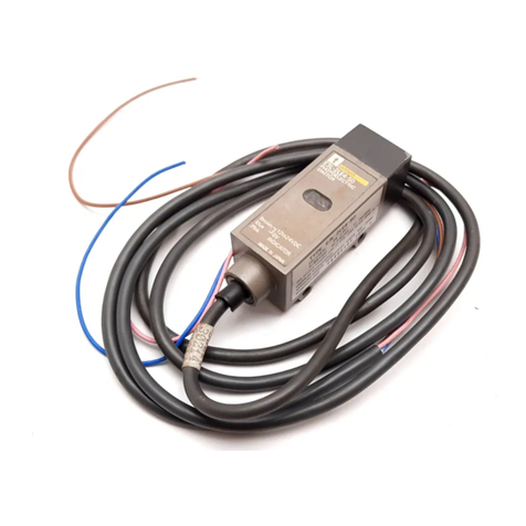
●E3L-2RC4
■SLIT DIAMETER AND DETECTING DISTANCE (reference value)
Slit diameter
No-slit
Detecting distance
30 cm
1 m
2 m
3 m
6 m
9 m
10 m
Detectable object
■OUTPUT CIRCUIT DIAGRAM AND TIME CHART
Cord color
Item power polarity
Output circuit
Time chart
Brown
+
Blue
−
Brown
−
Blue
+
ON at incident light ON at shielded light
■INDICATORS
Status
Stable
incident light
Unstable
incident light
Stable
shielded light
Unstable
shielded light
Indicator on/off
Red indicator at
incident/shielded light
Incident light
(Red indicator: ON)
Shielded light
(Red indicator: OFF)
Temperature fluctuation allowance
indicated by green indicator
Stable operation within rated
temperature range
(Green indicator: ON)
Stable operation within rated
temperature range
(Green indicator: ON)
■CONNECTIONS
●Connection to load such as relay and photo-coupler
Model
Item
Load condition
Connection
Note
E3L-2RC4
Dark ON: The load operates when the light is interrupted.
■OPTICAL AXIS ADJUSTMENT
●E3L-2LRC4
■DIMENSIONS
●E3L-2LRC4
●E3L-2LC4
To put projector into the light indication mode connect the
pink wire of model E3L-2LRC4 and the black wire of model
E3L-2DC4 together as shown by the dotted line.
For the power indication mode connect the blue wire.
Output transistor's
operating condiction
Opaque material dia 0.1
Opaque material dia 0.5
Opaque material dia 0.85
Opaque material dia 1
Opaque material dia 2
Opaque material dia 3
Opaque material dia 11
dia 0.1
dia 0.5
dia 0.85
dia 1
dia 2
dia 3
●Precautions
●Safety for laser products
E3L-2RC4
Model
LASER
PHOTOELECTRIC SWITCH
1.
3.
2.
120
100
80
OFF
OFF
OFF
OFF
5. 6.
ON ON
ON
ON
O.L×1.2
O.L
O.L×0.8
APERTURE LABEL CERTIFICATION LABEL
CAUTION
LABEL
Green Red
Green Red
Green Red
Green Red
Load
Photoelectric
switch main
circuit
0V
OUT
Brown 12 to 24V DC
Black
Blue
2.2
Ω
Incident
light
indicator
Stability
level
indicator
Between brown and black Between blue and black
LIGHT indicator
(Red)
Output transistor
Load (relay)
Incident
interrupted
ON
OFF
ON
OFF
Operation
Reset
LIGHT indicator
(Red)
Output transistor
Load (relay)
Incident
interrupted
ON
OFF
ON
OFF
Operation
Reset
12 to
24 VDC
12 to
24 VDC
blue
0V
brown
pink
E3L-2LRC4 E3L-2DC4
brown
blue
Model E3L-2LRC4
(Tc=25℃,40μ
W)
T:60μsec ts:5μsec f:16.7KHz
This product complies with 21 CFR 1040,10 and 1040,1
1
OMRON Corporation
KARASUMA NANAJO, SHIMOGYO-KU, KYOTO, 600
JAPAN MANUFACTURED
AVOID
EXPOSURE
Laser radiation
is emitted from
this aperture
CAUTION
LASER RADIATION
DO NOT STARE INTO BEAM
PEAK POWER 480
μ
w
WAVE LENGTH 670 nm
CLASS LASER PRODUCT
55
20 20
6.5 25.4
39
5
7(5)
4.2
SENSITIVITY ADJUSTER
55
22.2
12
22
32
1.6
20.4
2-M4 SLOTTED
HEXAGON BOLTS
LENS
(4dia)
23
20
20 20
2-MOUNTING HOLES
2-MOUNTING HOLES
6.5 25.4
39
5
7(5)
13dia
13dia
4.2
OPERATION
INDICATOR
OPERATION
INDICATOR
MOUNTING
BRACKET
COAD 4dia(18/0.12dia)3 CORE
STANDARD LENGTH 2M
COAD 4.5dia(18/0.12dia)3 CORE
STANDARD LENGTH 2M
4.
Red Green
Load
black
0V
25.4
2-M4
MOUNTING SCREW HOLES
25.4
2-M4
MOUNTING SCREW HOLES
22.2
12
22
32
1.6
20.4
2-M4 SLOTTED
HEXAGON BOLTS
LENS
(11dia)
23
20
MOUNTING
BRACKET
