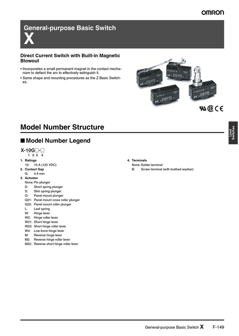
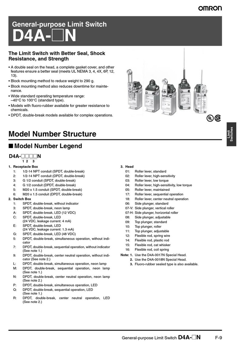
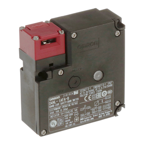
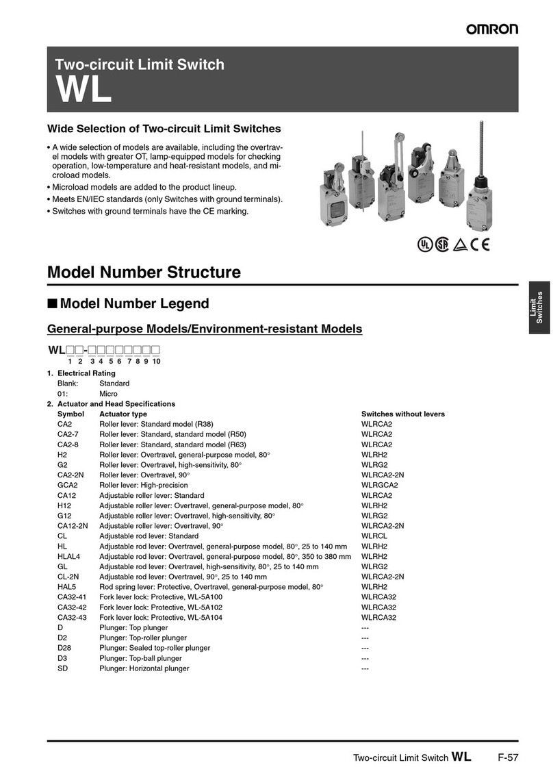
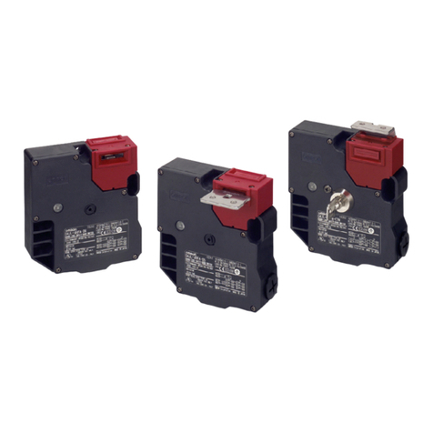
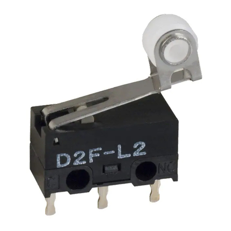
Omron Z User manual

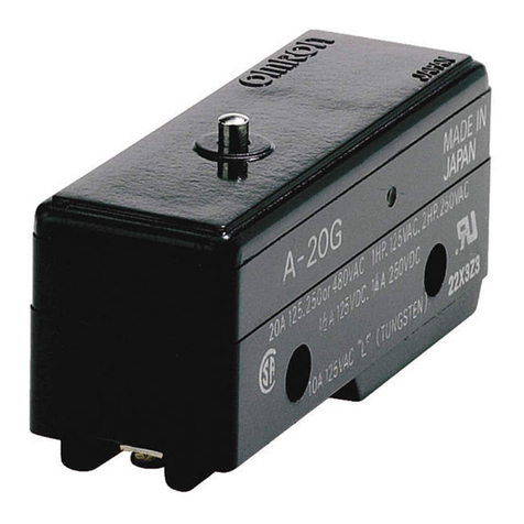
General-purpose Basic Switch ZF-157
Limit
Switches
General-purpose Basic Switch
Z
Best-selling Basic Switch Boasting High
Precision and Wide Variety
• A large switching capacity of 15 A with high repeat accuracy.
• A wide range of variations in contact form for your selection: ba-
sic, split-contact, maintained-contact, and adjustable contact
gap types.
• A series of standard models for micro loads is available.
• A series of molded terminal-type models incorporating safety
terminal protective cover is available.
Model Number Structure
■Configuration
Basic Models
General-purpose
A variety of actuators is available for a wide range of application.
The contact mechanism of models for micro loads is a crossbar type
with gold-alloy contacts, which ensures highly reliable operations for
micro loads.
Contact Gap:
H: 0.25 mm (high-sensitivity, micro voltage current load)
G: 0.5 mm (standard)
E: 1.8 mm (high-capacity)
F: 1.0 mm (split-contact models)
Split-contact Models
This type is identical in construction to the general-purpose basic
switch except that it has two pairs of simultaneous acting contacts by
splitting moving contacts.
Since the moving contacts are connected to a common terminal,
either parallel or series connection is possible.
Highly reliable micro load switching is ensured if the model is used as
a twin-contact switch.
Maintained-contact Models
The maintained-contact type has a reset button at the bottom of the
switch case, in addition to the pushbutton (plunger) located on the
opposite side of the reset button. Use these buttons alternately.
Since the Switch has greater pretravel than overtravel, it is suitable
for use in reversible control circuits, manual reset circuits, safety limit
circuits, and other circuits which are not preferable for automatic
resetting. (For further details, refer to individual datasheets.)
Basic models
Split-contact models
Maintained-contact models
General-purpose
Drip-proof Without terminal protective cover
With terminal protective cover
Molded terminal
General-purpose
Refer to page 3.
Refer to page 5.
Refer to page 4.
Refer to page 5.
General-purpose
Refer to individual datasheets.
(Contact your OMRON representative).
Refer to individual datasheets.
(Contact your OMRON representative).

F-158 General-purpose Basic Switch Z
■Model Number Legend
Basic Models
1. Ratings
01: 0.1 A (for micro load)
15: 15 A
2. Contact Gap
H: 0.25 mm (high-sensitivity, micro load)
G: 0.5 mm (standard)
E: 1.8 mm (high-capacity)
3. Actuator
None: Pin plunger
S: Slim spring plunger
D: Short spring plunger
K: Spring plunger (medium OP)
K3: Spring plunger (high OP)
Q3: Panel mount plunger (low OP)
Q: Panel mount plunger (medium OP)
Q8: Panel mount plunger (high OP)
Q22: Panel mount roller plunger
Q21: Panel mount cross roller plunger
L: Leaf spring (high OF)
L2: Roller leaf spring
W21: Short hinge lever
W: Hinge lever (low OF)
W3: Hinge lever (medium OF)
W32: Hinge lever (high OF)
W4: Low-force hinge lever
W44: Long hinge lever
W78: Low-force wire hinge lever (low OF)
W52: Low-force wire hinge lever (high OF)
W22: Short hinge roller lever
W2: Hinge roller lever
W25: Hinge roller lever (large roller)
W49: Short hinge cross roller lever
W54: Hinge cross roller lever
W2277: Unidirectional short hinge roller lever (Low OF)
M: Reverse hinge lever
M22: Reverse short hinge roller lever
M2: Reverse hinge roller lever
NJ: Flexible rod (high OF)
NJS: Flexible rod (low OF)
4. Degree of Protection
None: General-purpose
55: Drip-proof
A55: Drip-proof (including the terminals)
5. Terminals
None: Solder terminal
B: Screw terminal (with toothed washer)
B5V: Screw terminal with terminal cover (for Z-15G@A55 only)
Note: For combinations of models, refer to the following pages.
Split-contact Models
1. Ratings
10: 10 A
2. Contact Gap
F: 1 mm (high-capacity)
3. Actuator
None: Pin plunger
S: Slim spring plunger
D: Short spring plunger
Q: Panel mount plunger
Q22: Panel mount roller plunger
W: Hinge lever
W22: Short hinge roller lever
W2: Hinge roller lever
M22: Reverse short hinge roller lever
4. Construction
Y: Split-contact models
5. Terminals
None: Solder terminal
B: Screw terminal (with toothed washer)
Maintained-contact Models
1. Ratings
15: 15 A
2. Contact Gap
E: 1.8 mm (High capacity)
3. Actuator
None: Pin plunger
S: Slim spring plunger
W: Hinge lever
4. Structure
R: Maintained-contact models
1 2 3 4 5
Z-@@@@-@
1 2 3 4 5
Z-10F@Y-B
1 2 3 4
Z-15-E@R

General-purpose Basic Switch ZF-159
Limit
Switches
Ordering Information
■List of Models
Basic Models (General-purpose)
Actuator Standard High-sensitivity High-capacity Micro load
G (0.5 mm) H (0.25 mm) E (1.8 mm) H (0.25 mm)
Solder terminal Z-15G Z-15H Z-15E Z-01H
Screw terminal Z-15G-B Z-15H-B Z-15E-B Z-01H-B
Solder terminal Z-15GS Z-15HS --- Z-01HS
Screw terminal Z-15GS-B Z-15HS-B --- Z-01HS-B
Solder terminal Z-15GD Z-15HD Z-15ED Z-01HD
Screw terminal Z-15GD-B Z-15HD-B Z-15ED-B Z-01HD-B
Low OP Solder terminal Z-15GQ3 --- --- ---
Screw terminal Z-15GQ3-B
Medium OP Solder terminal Z-15GQ Z-15HQ Z-15EQ Z-01HQ
Screw terminal Z-15GQ-B Z-15HQ-B Z-15EQ-B Z-01HQ-B
High OP Solder terminal Z-15GQ8 --- --- ---
Screw terminal Z-15GQ8-B
Solder terminal Z-15GQ22 Z-15HQ22 Z-15EQ22 ---
Screw terminal Z-15GQ22-B Z-15HQ22-B Z-15EQ22-B ---
Solder terminal Z-15GQ21 Z-15HQ21 Z-15EQ21 ---
Screw terminal Z-15GQ21-B Z-15HQ21-B Z-15EQ21-B
Solder terminal Z-15GL --- --- ---
Screw terminal Z-15GL-B
Solder terminal Z-15GL2 --- --- ---
Screw terminal Z-15GL2-B
Solder terminal Z-15GW21 --- --- ---
Screw terminal Z-15GW21-B
Low OF Solder terminal Z-15GW Z-15HW --- ---
Screw terminal Z-15GW-B Z-15HW-B --- ---
Medium OF Solder terminal Z-15GW3 --- --- ---
Screw terminal Z-15GW3-B
High OF Solder terminal Z-15GW32 ---
Screw terminal Z-15GW32-B
Solder terminal Z-15GW4 Z-15HW24 --- ---
Screw terminal Z-15GW4-B Z-15HW24-B ---
Low OF Solder terminal --- Z-15HW78 --- ---
Screw terminal Z-15HW78-B ---
High OF Solder terminal --- Z-15HW52 --- ---
Screw terminal Z-15HW52-B ---
Solder terminal Z-15GW22 Z-15HW22 Z-15EW22 Z-01HW22
Screw terminal Z-15GW22-B Z-15HW22-B Z-15EW22-B Z-01HW22-B
Solder terminal Z-15GW49 --- --- ---
Screw terminal Z-15GW49-B
Parallel Solder terminal Z-15GW2 Z-15HW2 --- ---
Screw terminal Z-15GW2-B Z-15HW2-B --- ---
Large roller Solder terminal Z-15GW25 --- --- ---
Screw terminal Z-15GW25-B
Pin plunger
Slim spring plunger
Short spring
plunger
Panel mount
plunger
Panel mount roller
plunger
Panel mount cross
roller plunger
Leaf spring
Roller leaf spring
Short hinge lever
Hinge lever
Low-force hinge lever
Low-force wire
hinge lever
Short hinge roller lever
Short hinge cross
roller lever
Hinge roller lever

F-160 General-purpose Basic Switch Z
Note: The pin plungers of reverse-type models are continuously pressed by the actuator levers with compression coil springs and the pin plungers
are freed by operating the levers. Reverse-type models are highly vibration- and shock-resistive because the pin plungers are normally
pressed.
Minimum Order Lot
The following models are available at the minimum order lot specified below. Orders must be placed per lot.
Split-contact Models
Solder terminal Z-15GW54 --- --- ---
Screw terminal Z-15GW54-B
Solder terminal Z-15GW2277 --- --- ---
Screw terminal Z-15GW2277-B
Solder terminal Z-15GM --- --- ---
Screw terminal Z-15GM-B
Solder terminal Z-15GM22 --- --- ---
Screw terminal Z-15GM22-B
Solder terminal Z-15GM2 --- --- ---
Screw terminal Z-15GM2-B
Actuator Standard High-sensitivity High-capacity Micro load
G (0.5 mm) H (0.25 mm) E (1.8 mm) H (0.25 mm)
Hinge cross
roller lever
Unidirectional short
hinge roller lever
Reverse hinge lever
(see note)
Reverse short hinge
roller lever (see note)
Reverse hinge roller lever
(see note)
Actuator Standard High-sensitivity Minimum order lot (pcs)
G (0.5 mm) H (0.25 mm)
Short spring plunger Z-15GD-B --- 10
Panel mount plunger Z-15GQ
Z-15GQ-B
Z-15GQ8-B
---
Panel mount roller plunger Z-15GQ22
Z-15GQ22-B
---
Panel mount cross roller plunger Z-15GQ21-B ---
Short hinge lever Z-15GW21-B ---
Hinge lever Z-15GW
Z-15GW-B
---
Low-force hinge lever Z-15GW4-B Z-15HW24-B
Low-force hinge wire lever --- Z-15HW78-B
Short hinge roller lever Z-15GW22
Z-15GW22-B
---
Hinge roller lever Z-15GW2
Z-15GW2-B
---
Reverse short hinge roller lever Z-15GM22-B ---
Reverse hinge roller lever Z-15GM2-B ---
Actuator F (1.0 mm)
Solder terminal ---
Screw terminal Z-10FY-B
Solder terminal ---
Screw terminal Z-10FSY-B
Solder terminal ---
Screw terminal Z-10FDY-B
Medium OP Solder terminal ---
Screw terminal Z-10FQY-B
Pin plunger
Slim spring plunger
Short spring plunger
Panel mount plunger

General-purpose Basic Switch ZF-161
Limit
Switches
Note: The pin plungers of reverse-type models are continuously pressed by the actuator levers with compression coil springs and the pin plungers
are freed by operating the levers. Reverse-type models are highly vibration- and shock-resistive because the pin plungers are normally
pressed.
Maintained-contact Models
Basic Models (Drip-proof Models)
Solder terminal ---
Screw terminal Z-10FQ22Y-B
Low OP Solder terminal ---
Screw terminal Z-10FWY-B
Solder terminal ---
Screw terminal Z-10FW22Y-B
Parallel Solder terminal ---
Screw terminal Z-10FW2Y-B
Solder terminal ---
Screw terminal Z-10FM22Y-B
Actuator F (1.0 mm)
Panel mount roller
plunger
Hinge lever
Short hinge roller
lever
Hinge roller lever
Reverse short
hinge roller lever
Actuator Maintained-contact model
Z-15ER
Z-15ESR
Z-15EWR
Pin plunger
Slim spring plunger
Hinge lever
Actuator Basic model (drip-proof)
Standard Micro load
G (0.5 mm) H (0.25 mm)
Without drip-proof terminal
protective cover With drip-proof terminal
protective cover Without drip-proof terminal
protective cover
Solder terminal Z-15G55 --- Z-01H55
Screw terminal Z-15G55-B Z-15GA55-B5V Z-01H55-B
Solder terminal Z-15GD55 --- Z-01HD55
Screw terminal Z-15GD55-B Z-01HD55-B
Medium OP Solder terminal Z-15GK55 --- ---
Screw terminal Z-15GK55-B
HIgh OP Solder terminal Z-15GK355 --- ---
Screw terminal Z-15GK355-B Z-15GK3A55-B5V
Medium OP Solder terminal Z-15GQ55 --- ---
Screw terminal Z-15GQ55-B Z-15GQA55-B5V
Solder terminal Z-15GQ2255 --- ---
Screw terminal Z-15GQ2255-B Z-15GQ22A55-B5V
Solder terminal --- --- ---
Screw terminal Z-15GQ2155-B Z-15GQ21A55-B5V
Solder terminal Z-15GL55 --- ---
Screw terminal Z-15GL55-B
Solder terminal Z-15GL255 --- ---
Screw terminal Z-15GL255-B
Solder terminal Z-15GW2155 --- ---
Screw terminal Z-15GW2155-B
Solder terminal Z-15GW4455 --- ---
Screw terminal Z-15GW4455-B Z-15GW44A55-B5V
Solder terminal Z-15GW55 --- ---
Screw terminal Z-15GW55-B Z-15GWA55-B5V
Solder terminal Z-15GW2255 --- Z-01HW2255
Screw terminal Z-15GW2255-B Z-15GW22A55-B5V Z-01HW2255-B
Pin plunger
Short spring plunger
Spring plunger
Panel mount
plunger
Panel mount
roller plunger
Panel mount cross
roller plunger
Leaf spring
Roller leaf spring
Short hinge lever
Long hinge lever
Hinge lever
Short hinge
roller lever

F-162 General-purpose Basic Switch Z
Note: 1. The pin plungers of reverse-type models are continuously pressed by the actuator levers with compression coil springs and the pin plung-
ers are freed by operating the levers.
2. The tip is made of resin.
Minimum Order Lot
The following models are available at the minimum order lot specified below. Orders must be placed per lot.
Basic Models (Drip-proof High-sensitivity Models)
Parallel Solder terminal Z-15GW255 --- ---
Screw terminal Z-15GW255-B Z-15GW2A55-B5V
Solder terminal Z-15GW227755 --- ---
Screw terminal Z-15GW227755-B Z-15GW2277A55-B5V
Solder terminal Z-15GM55 --- ---
Screw terminal Z-15GM55-B
Solder terminal Z-15GM2255 --- ---
Screw terminal Z-15GM2255-B
Solder terminal Z-15GM255 --- ---
Screw terminal Z-15GM255-B
Solder terminal Z-15GNJ55 --- ---
Screw terminal Z-15GNJ55-B
Actuator Basic model (drip-proof)
Standard Micro load
G (0.5 mm) H (0.25 mm)
Without drip-proof terminal
protective cover With drip-proof terminal
protective cover Without drip-proof terminal
protective cover
Hinge roller lever
Unidirectional short
hinge roller lever
Reverse hinge lever
(see note 1)
Reverse short hinge
roller lever (see note 1)
Reverse hinge roller
lever (see note 1)
Flexible rod (coil spring)
(see note 2)
Actuator Standard High-sensitivity Minimum order lot
G (0.5 mm) H (0.25 mm)
Short spring plunger Z-15GD55-B --- --- 10
Spring plunger Z-15GK55-B --- ---
Hinge lever Z-15GW4455-B
Z-15GW55
Z-15GW55-B
--- ---
Short hinge roller lever Z-15GW2255
Z-15GW2255-B
--- ---
Hinge roller lever Z-15GW255-B --- ---
Flexible rod (coil spring) Z-15GNJ55-B --- ---
Flexible rod (steel wire) --- --- Z-15HNJS55-B
Actuator High-sensitivity
H (0.25 mm)
Solder terminal Z-15HNJS55
Screw terminal Z-15HNJS55-B
Flexible rod (steel wire)

General-purpose Basic Switch ZF-163
Limit
Switches
Specifications
■Approved Standards
■Approved Standard Ratings
UL508 (File No. E41515)
CSA C22.2 No.55 (File No. LR21642)
EN (EN61058-1)
Note: Consult with OMRON about approved part numbers by standards.
■Ratings
Z-15 (Except Micro Load and Flexible Rod Models)
Note: Figures in parentheses are for the Z-15HW52 and Z-15HW78(-B) models, the AC ratings of these models are 125 and 250 V only.
Z-15 (Flexible Rod Models)
Agency Standard File No.
UL UL508 E41515
CSA CSA C22.2 No. 55 LR21642
TÜV Rheinland EN61058-1 R9451585
Rated voltage Z-15 Z-10F Z-01H
125 VAC 15 A 1/8 HP 6 A 1/10 HP 0.1 A
250 VAC 15 A 1/4 HP 6 A 1/8 HP ---
480 VAC 15 A 6 A ---
30 VDC --- --- 0.1 A
125 VDC 0.5 A 0.6 A ---
250 VDC 0.25 A 0.3 A ---
Rated voltage Z-15H@-B Z-15G@-B Z-01H@-B
250 VAC 15 A 15 A ---
125 VAC --- --- 0.1 A
30 VDC --- --- 0.1 A
Item Non-inductive load Inductive load
Resistive load Lamp load Inductive load Motor load
ModelRatedvoltageNCNONCNONCNONCNO
G, H, E 125 VAC
250 VAC
500 VAC
15 (10) A (see note)
10 A
3 A
2.5 A
1.5 A
1.5 A
1.25 A
0.75 A
15 (10) A (see note)
6 A
5 A
3 A
1.5 A
2.5 A
1.5 A
0.75 A
G8VDC
14 VDC
30 VDC
125 VDC
250 VDC
15 A
15 A
6 A
0.5 A
0.25 A
3 A
3 A
3 A
0.5 A
0.25 A
1.5 A
1.5 A
1.5 A
0.5 A
0.25 A
15 A
10 A
5 A
0.05 A
0.03 A
5 A
5 A
5 A
0.05 A
0.03 A
2.5 A
2.5 A
2.5 A
0.05 A
0.03 A
H8VDC
14 VDC
30 VDC
125 VDC
250 VDC
15 A
15 A
2 A
0.4 A
0.2 A
3 A
3 A
2 A
0.4 A
0.2 A
1.5 A
1.5 A
1.4 A
0.4 A
0.2 A
15 A
10 A
1 A
0.03 A
0.02 A
5 A
5 A
1 A
0.03 A
0.02 A
2.5 A
2.5 A
1 A
0.03 A
0.02 A
E8VDC
14 VDC
30 VDC
125 VDC
250 VDC
15 A
15 A
15 A
0.75 A
0.3 A
3 A
3 A
3 A
0.75 A
0.3 A
1.5 A
1.5 A
1.5 A
0.75 A
0.3 A
15 A
15 A
10 A
0.4 A
0.2 A
5 A
5 A
5 A
0.4 A
0.2 A
2.5 A
2.5 A
2.5 A
0.4 A
0.2 A
Rated voltage Non-inductive load Inductive load
Resistive load Lamp load Inductive load Motor load
NC NO NC NO NC NO NC NO
125 VAC
250 VAC 15 A 2 A
1 A
1 A
0.5 A
7 A
5 A
2.5 A
1.5 A
2 A
1 A
8 VDC
14 VDC
30 VDC
125 VDC
250 VDC
15 A
15 A
2 A
0.4 A
0.2 A
2 A
2 A
2 A
0.4 A
0.2 A
1 A
1 A
1 A
0.4 A
0.2 A
7 A
7 A
1 A
0.03 A
0.02 A
3 A
3 A
1 A
0.03 A
0.02 A
1.5 A
1.5 A
0.5 A
0.03 A
0.02 A

F-164 General-purpose Basic Switch Z
Z-01H
Z-10F
Note: 1. The above current ratings are the values of the steady-state current.
2. Inductive load has a power factor of 0.4 min. (AC) and a time constant of 7 ms max. (DC).
3. Lamp load has an inrush current of 10 times the steady-state current.
4. Motor load has an inrush current of 6 times the steady-state current.
5. The normally closed and normally open ratings of reverse hinge lever models are opposite to each other.
6. The AC ratings of molded terminals are 125 and 250 V only.
7. The ratings values apply under the following test conditions:
Ambient temperature: 20±2°C
Ambient humidity: 65±5%
Operating frequency: 20 operations/min
Rated voltage Resistive load
NC NO
125 VAC 0.1 A
8 VDC
14 VDC
30 VDC
0.1 A
0.1 A
0.1 A
Model Rated voltage Non-inductive load Inductive load
Resistive load Lamp load Inductive load Motor load
NC NO NC NO NC NO NC NO
Series
connection 125 VAC
250 VAC 10 A
10 A
4 A
2.5 A
2 A
1.5 A
6 A 5 A
3 A
2.5 A
1.5 A
30 VDC
125 VDC
250 VDC
10 A
1 A
0.6 A
4 A
1 A
0.6 A
2 A
1 A
0.6 A
6 A
0.1 A
0.05 A
6 A
0.1 A
0.05 A
3 A
0.1 A
0.05 A
Parallel
connection 125 VAC
250 VAC 6 A
6 A
3 A
2.5 A
1.5 A
1.25 A
4 A
4 A
4 A
2 A
2 A
1 A
30 VDC
125 VDC
250 VDC
6 A
0.6 A
0.3 A
4 A
0.6 A
0.3 A
2 A
0.6 A
0.3 A
4 A
0.1 A
0.05 A
6 A
0.1 A
0.05 A
3 A
0.1 A
0.05 A

General-purpose Basic Switch ZF-165
Limit
Switches
■Characteristics
Note: 1. The values are for the plunger models. (For the lever models, the values are at the plunger section.) (Contract your OMRON represen-
tative for other models.)
2. The values are for the Z-15G pin plunger.
3. The values are for the Z-10FY-B.
4. The values are for the pin plunger. The durability for models other than the pin plunger is 10,000,000 min.
5. Malfunction: 1 ms max.
Item Basic
(except micro load
and flexible rod)/
maintained
contact
Z-15
Basic
(micro load)
Z-01H
Basic
(flexible rod)
Z-15
Split-contact
Z-10F
Operating speed
(see note) 0.01 mm to 1 m/s (see note 1) 1 mm to 1 m/s 0.1 mm to 1 m/s (see note 1)
Operating frequency Mechanical: 240 operations/min
Electrical: 20 operations/min
Mechanical: 120 operations/min
Electrical: 20 operations/min
Mechanical: 240 operations/min
Electrical: 20 operations/min
Insulation resistance 100 MΩmin. (at 500 VDC)
Contact resistance 15 mΩmax. (initial
value)
50 mΩmax. (initial
value)
15 mΩmax. (initial value) 25 mΩmax. (initial value)
Dielectric strength Between contacts of same polarity
Contact gap G: 1,000 VAC, 50/60 Hz for
1min
Contact gap H: 600 VAC, 50/60 Hz for
1min
Contact gap E: 1,500 VAC, 50/60 Hz for
1min
Between current-carrying metal parts and
ground, and between each terminal and
non-current-carrying metal parts
2,000 VAC, 50/60 Hz for 1 min
Between contacts of same polarity
Contact gap G: 1,000 VAC, 50/
60 Hz for 1 min
Contact gap H: 600 VAC, 50/ 60 Hz
for 1 min
Between current-carrying metal
parts and ground, and between each
terminal and non-current-carrying
metal parts
2,000 VAC, 50/60 Hz for 1 min
Between contacts of same polarity
Contact gap F: 1,500 VAC, 50/
60 Hz for 1 min
Between current-carrying metal
parts and ground, and between each
terminal and non-current-carrying
metal parts
2,000 VAC, 50/60 Hz for 1 min
Vibration resistance Malfunction: 10 to 55 Hz, 1.5-mm double
amplitude (see note 5)
Malfunction: 10 to 20 Hz, 1.5-mm
double amplitude (see note 5)
Malfunction: 10 to 55 Hz, 1.5-mm
double amplitude (see note 5)
Shock resistance Destruction: 1,000 m/s2
{approx. 100G} max.
Malfunction: 300 m/s2
{approx. 30G} max.
(see note 2, 5)
Destruction: 1,000 m/s2{approx.
100G} max.
Malfunction:50m/s
2
{approx. 5G} max.
(see note 5)
Destruction: 1,000 m/s2{approx.
100G} max.
Malfunction: 300 m/s2.
{approx. 30G} max.
(see note 3, 5)
Durability Mechanical:
Contact gap G, H: 20,000,000 operations
min. (see note 4)
Contact gap E: 300,000 operations
Electrical:
Contact gap G, H: 500,000 operations
min.
Contact gap E: 100,000 operations
min.
Mechanical: 1,000,000 operations
min.
Electrical: 100,000 operations
min.
Mechanical: 500,000 operations
min. (see note 1)
Electrical: 100,000 operations
min.
Degree of protection General-purpose: IP00
Drip-proof: IP62
Degree of protection
against electric shock Class I
Proof tracking index
(PTI) 175
Switch category D (IEC335-1)
Ambient temperature Operating:
General-purpose: −25°C to 80°C (with no icing)
Drip-proof: −15°C to 80°C (with no icing)
Ambient humidity Operating:
General-purpose: 35% to 85%
Drip-proof: 35% to 95%
Weight Approx. 22 to 58 g Approx. 42 to 48 g Approx. 34 to 61 g

F-166 General-purpose Basic Switch Z
■Contacts Specification
■Contact Form
Basic Models
General-purpose
Contact Form (SPDT)
Split-contact Models
Contact Form (Split-contact)
Connection Example
Maintained-contact Models
Contact Form (Maintained-contact)
Item Z-15 Z-01H Z-10F
Contacts Shape Rivet Single crossbar Rivet
Material Silver alloy Gold alloy Silver alloy
Inrush current NC 30 A max. 0.1 A max. 40 A max.
NO 15 A max. 0.1 A max. 20 A max.
COM NO NC
Note: The Z-15GM is a reversible model and the NO and
NC positions are reversed.
COM NO
NO
NC
NC
LL
L
L
L
L
Series Connection Parallel Connection
COM NO NC
Pushbutton for resetting

General-purpose Basic Switch ZF-167
Limit
Switches
Engineering Data
■Mechanical Durability ■Electrical Durability
Nomenclature
■Drip-proof Construction
Without Terminal Protective Cover
With Terminal Protective Cover
10
5
1
0.5
0.1
0246810121416
100
70
50
30
20
10
7
5
3
2
1
0 0.1 0.2 0.3 0.4 0.5 0.6 0.7 0.8
Z-15G Z-15G
Overtravel (mm) Switching Current (A)
125 VAC cosφ= 0.4
250 VAC cosφ= 1
500 VAC cosφ= 1
125 VAC cosφ= 1
500 VAC cosφ= 0.4
Durability (x106operations)
Ambient temperature: 20±2°C
Ambient humidity: 65±5%
Without load
Operating frequency: 240 operations/min
Ambient temperature: 20±2°C
Ambient humidity: 65±5%
Operating frequency: 20 operations/min.
250 VAC
cosφ= 0.4
Rubber boot
Movable spring
Fixed contact (b)
Fixed contact (a)
Spring pivot
Movable contact
Glued surface (adhesive is
filled between case and cover)
Rubber boot (weather-resistive
chloroprene is used)
Stainless-steel stopper
(improves sealing)
Rubber packing (improves
sealing between switch
housing and terminal cover)
Terminal protective covers are sold separately
for maintenance purposes, which can be, how-
ever, used with the Z-@-B5V models only.

F-168 General-purpose Basic Switch Z
Dimensions
Note: 1. Unless otherwise indicated, all units are in millimeters.
2. Unless otherwise specified, a tolerance of ±0.4 mm applies to all dimensions.
■Dimensions and Operating Characteristics
Basic Models (General-purpose) & Split-contact Models
The models, illustrations, and graphics are for screw-terminal models (-B). The “-A” at the end of the model number for solder terminal models has
been omitted. For details of the terminals, refer to Terminals above.
Z-15G-B Z-15H-B Z-15E-B Z-01H-B Z-10FY-B
OF
RF min.
PT max.
OT min.
MD max.
2.45 to 3.43 N
{250 to 350 gf}
1.12 N {114 gf}
0.4 mm
0.13 mm
0.05 mm
1.96 to 2.75 N
{200 to 280 gf}
1.12 N {114 gf}
0.3 mm
0.13 mm
0.025 mm
6.12 to 7.85 N
{625 to 800 gf}
1.12 N {114 gf}
0.8 mm
0.13 mm
0.13 mm
2.45 N {250 gf} max.
0.78 N {80 gf}
0.5 mm
0.13 mm
0.04 mm
4.46 to 7.26 N
{455 to 740 gf}
1.12 N {114 gf}
0.8 mm
0.13 mm
0.1 mm
OP 15.9±0.4 mm
4.2
+0.075
−0.025
PT
OP
25.4±0.1 11.9
49.2
23.3±0.25
9.2
24.2
17.45±0.2
Pin Plunger
4.2
+0.075
dia. hole
−0.025
2.3 dia.
2.3SR (see note)
4.36
+0.1
dia.
−0.05
Note: Stainless-steel plunge
r
Z-15G-B, Z-15E-B
Z-15H-B, Z-01H-B
Z-10FY-B
Z-15GS-B Z-15HS-B Z-01HS Z-10FSY-B
OF
RF min.
PT max.
OT min.
MD max.
2.45 to 3.43 N
{250 to 350 gf}
1.12 N {114 gf}
0.4 mm
1.6 mm
0.05 mm
1.96 to 2.79 N
{200 to 285 gf}
1.12 N {114 gf}
0.3 mm
1.6 mm
0.025 mm
2.45 N {250 gf} max.
0.78 N {80 gf}
0.5 mm
1.6 mm
0.05 mm
4.46 to 7.26 N
{455 to 740 gf}
1.12 N {114 gf}
0.8 mm
1.6 mm
0.1 mm
OP 28.2±0.5 mm
4.2
+0.075
−0.025
23.3±0.25
PT
OP
25.4±0.1 11.9
49.2
9.2
24.2
17.45±0.2
Slim Spring Plunger
4.2
+0.075
dia. hole
−0.025
5.2 dia.
4.36
+0.1
dia.
−0.05
4 dia.
9 dia.
Z-15GS-B, Z-15HS-B,
Z-01HS-B, Z-10FSY-B
(see
note)
Note: Stainless-steel plunger
(flat, 1R chamfered)

General-purpose Basic Switch ZF-169
Limit
Switches
Z-15GD-B Z-15HD-B Z-15ED-B Z-01HD-B Z-10FDY-B
OF
RF min.
PT max.
OT min.
MD max.
2.45 to 3.43 N
{250 to 350 gf}
1.12 N {114 gf}
0.4 mm
1.6 mm
0.05 mm
1.96 to 2.79 N
{200 to 285 gf}
1.12 N {114 gf}
0.3 mm
1.6 mm
0.025 mm
6.13 to 7.85 N
{625 to 800 gf}
1.12 N {114 gf}
0.8 mm
1.6 mm
0.13 mm
2.45 N {250 gf} max.
0.78 N {80 gf}
0.5 mm
1.6 mm
0.05 mm
4.46 to 7.26 N
{455 to 740 gf}
1.12 N {114 gf}
0.8 mm
1.6 mm
0.1 mm
OP 21.5±0.5 mm
24.2
9.2
17.45±0.2
23.3±0.25
4.2+0.075
−0.025
PT
OP
25.4±0.1 11.9
49.2
Short Spring Plunger
4.2+0.075 dia. hole
−0.025
12.3 dia.
4.36+0.1 dia.
−0.05
10 dia.
7.15 dia.
Note: Plated iron plunge
r
Z-15GD-B, Z-01HD-B
Z-15HD-B, Z-10FDY-B
Z-15ED-B
12SR
(see
note)
4.2+0.075
−0.025
23.3±0.25
PT
OP13.1
16.3
25.4±0.1 11.9
49.2
9.2
17.45±0.2
Panel Mount Plunger
4.2+0.075 dia. hole
−0.025
8.35 dia.
4.36+0.1 dia.
−0.05
M12 ×1 mounting screw
Two lock nuts (2 t ×15.6 width across flats)
16 dia.
Z-15GQ-B, Z-01HQ-B
Z-15HQ-B, Z-10FQY-B
Z-15EQ-B
(See
note 2)
11.9SR
(see
note 1)
Two hexagonal nuts (2 t ×14
width across flats)
Note: 1. Stainless-steel plunger
2. Imperfect screw part with a maxi-
mum length of 1.5 mm.
4.2+0.075
−0.025
23.3±0.25
PT
OP13.1
16.3
25.4±0.1 11.9
49.2
9.2
17.45±0.2
Z-15GQ3-B
4.2+0.075 dia. hole
−0.025
8.35 dia.
4.36+0.1 dia.
−0.05
16 dia.
Two lock nuts (2 t ×15.6 width across flats)
(See
note 2)
11.9SR
(see
note 1)
M12 ×1
mounting screw
Two hexagonal nuts (2 t ×14
width across flats)
Note: 1. Stainless-steel plunger
2. Imperfect screw part with a maxi-
mum length of 1.5 mm.
4.2+0.075
−0.025
23.3±0.25
PT
OP
13.1
16.3
25.4±0.1 11.9
49.2
9.2
17.45±0.2
Z-15GQ8-B
4.2+0.075 dia. hole
−0.025
8.35 dia.
4.36+0.1 dia.
−0.05
16 dia.
M3 ×10 (depth)
Two lock nuts (2 t ×15.6 width across flats)
(See
note 2)
8SR
(see
note
1) M12 ×1
mounting screw
Two hexagonal nuts (2 t ×14
width across flats)
Note: 1. Plated brass plunger
2. Imperfect screw part with a maxi-
mum length of 1.5 mm.

F-170 General-purpose Basic Switch Z
Note: 1. Do not use the M12 mounting screw and the case mounting hole at the same time, or excessive pulling force will be imposed on the
Switch and the case and cover may be damaged.
2. On the model Z-15GQ3-B, PT can be set to a value larger than that for the Z-15GQ.
3. On the model Z-15GQ8-B, operating position can be adjusted by providing a screw in the plunger section.
The M3 hole with a depth of 10 mm is a through hole. Take precautions so that no water or screw lock agent penetrates into the hole.
Note: Do not use the M12 mounting screw and the case mounting hole at the same time, or the case may be damaged.
Z-15GQ-B Z-15HQ-B Z-15EQ-B Z-01HQ-B Z-10FQY-B Z-15GQ3-B Z-15GQ8-B
OF
RF min.
PT max.
OT min.
MD max.
2.45 to 3.43 N
{250 to 350 gf}
1.12 N {114 gf}
0.4 mm
5.5 mm
0.05 mm
1.96 to 2.79 N
{200 to 285 gf}
1.12 N {114 gf}
0.3 mm
5.5 mm
0.025 mm
6.13 to 7.85 N
{625 to 800 gf}
1.12 N {114 gf}
0.8 mm
5.5 mm
0.13 mm
2.45 N {250 gf}
max.
0.78 N {80 gf}
0.5 mm
5.5 mm
0.05 mm
4.46 to 7.26 N
{455 to 740 gf}
1.12 N {114 gf}
0.8 mm
5.5 mm
0.1 mm
2.45 to 3.43 N
{250 to 350 gf}
1.12 N {114 gf}
4.2 mm
2.5 mm
2.2 mm
2.45 to 3.43 N
{250 to 350 gf}
1.12 N {114 gf}
0.5 mm
5.5 mm
0.05 mm
OP 21.8±0.8 mm 18.8±0.8 mm 32.5±1 mm
Z-15GQ22-B Z-15HQ22-B Z-15EQ22-B Z-10FQ22Y-B
OF
RF min.
PT max.
OT min.
MD max.
2.45 to 3.43 N
{250 to 350 gf}
1.12 N {114 gf}
0.4 mm
3.58 mm
0.05 mm
1.96 to 2.79 N
{200 to 285 gf}
1.12 N {114 gf}
0.3 mm
3.58 mm
0.025 mm
6.13 to 7.85 N
{625 to 800 gf}
1.12 N {114 gf}
0.8 mm
3.58 mm
0.13 mm
4.46 to 7.26 N
{455 to 740 gf}
1.12 N {114 gf}
1 mm
3.55 mm
0.1 mm
OP 33.4±1.2 mm
4.2
+0.075
−0.025
23.3±0.25
PT
OP
15.5
16.3
25.4±0.1 11.9
49.2
9.2
17.45±0.2
Panel Mount Roller Plunger
4.2
+0.075
dia. hole
−0.025
12.7 dia. ×4.8 (stainless-steel roller)
4.36
+0.1
dia.
−0.05
16 dia.
Z-15GQ22-B, Z-15EQ22-B
Z-15HQ22-B, Z-10FQ22Y-B
(See
note)
Two hexagonal nuts (3 t ×17
width across flats)
M12 ×1 mount-
ing screw
Note: Imperfect screw part with a
maximum length of 1.5 mm.
4.2
+0.075
−0.025
9.2
17.45±0.2
PT
OP
15.5
16.3
25.4±0.1 11.9
49.2
23.3±0.25
Panel Mount Cross Roller Plunger
4.2
+0.075
dia. hole
−0.025
12.7 dia. ×4.8 (stainless-steel roller)
4.36
+0.1
dia.
−0.05
16 dia.
Z-15GQ21-B, Z-15HQ21-B,
Z-15EQ21-B
(See
note)
Two hexagonal nuts (3 t ×17
width across flats)
M12 ×1 mount-
ing screw
Note: Imperfect screw part with a
maximum length of 1.5 mm.

General-purpose Basic Switch ZF-171
Limit
Switches
Note: Do not use the M12 mounting screw and the case mounting hole at the same time, or the case may be damaged.
Note: When operating, be sure not to ex-
ceed 1.6 mm.
Note: When operating, be sure not to ex-
ceed 1.6 mm.
Note: The external dimensions of the actuator vary.
Z-15GQ21-B Z-15HQ21-B Z-15EQ21-B
OF
RF min.
PT max.
OT min.
MD max.
2.45 to 3.43 N
{250 to 350 gf}
1.12 N {114 gf}
0.4 mm
3.58 mm
0.05 mm
1.96 to 2.79 N
{200 to 285 gf}
1.12 N {114 gf}
0.3 mm
3.58 mm
0.025 mm
6.13 to 7.85 N
{625 to 800 gf}
1.12 N {114 gf}
0.8 mm
3.58 mm
0.13 mm
OP 33.4±1.2 mm
OF max.
RF min.
OT min.
MD max.
1.38 N {141 gf}
0.14 N {14 gf}
1.6 mm (see note)
1.3 mm
FP max.
OP
20.6 mm
17.4±0.8 mm
4.2+0.075
−0.025
49.6±0.8
OP
FP
25.4±0.1 11.9
49.2
4.8
23.9
9.2
17.45±0.2
Leaf Spring
Z-15GL-B
4.36+0.1 dia.
−0.05
t = 0.3 (stainless-steel spring lever)
−0.025
4.2+0.075
dia. hole
OF max.
RF min.
OT min.
MD max.
1.38 N {141 gf}
0.14 M {14 gf}
1.6 mm (see note)
1.3 mm
FP max.
OP
31.8 mm
28.6±0.8 mm
4.2
+0.075
−0.025
46±0.8
OPFP
25.4±0.1 11.9
49.2
23.9
9.2
17.45±0.2
Roller Leaf Spring
Z-15GL2-B
4.2
+0.075
dia. hole
−0.025
4.36
+0.1
dia.
−0.05
9.5 dia. ×4 (plastic toller)
Note: Stainless-steel spring leve
r
t = 0.3
(see note)
OF max.
RF min.
OT min.
MD max.
1.57 N {160 gf}
0.27 N {28 gf}
2 mm
1 mm
FP max.
OP
24.8 mm
19±0.8 mm
4.2+0.075
−0.025
28.2R
26.2
16.9
20.2
25.4±0.1 11.9
49.2
OP FP
4.9
9.2
17.45±0.2
13.9
Short Hinge Lever
Z-15GW21-B
4.2+0.075 dia. hole
−0.025
4.36+0.1 dia.
−0.05
t = 1 (stainless-steel lever)
4.2+0.075
−0.025
63.5R
26.2
16.9
20.2
25.4±0.1 11.9
49.2
13.9 OP FP
4.9
9.2
17.45±0.2
Hinge Lever
4.2+0.075 dia. hole
−0.025
4.36+0.1 dia.
−0.05
t = 1 (stainless-steel lever)
Z-15GW-B, Z-15GW32-B
Z-15HW-B, Z-10FWY-B
Z-15GW3-B (Lever Length: 56R)
(see note)

F-172 General-purpose Basic Switch Z
Note: The AC rating is 10 A at 125 or 250 V.
Z-15GW-B Z-15HW-B Z-15GW32-B Z-10FWY-B Z-15GW3-B
OF max.
RF min.
OT min.
MD max.
0.69 N {70 gf}
0.14 N {14 gf}
5.6 mm
1.27 mm
0.66 N {67 gf}
0.14 N {14 gf}
5.6 mm
0.63 mm
1.47 to 1.96 N
{150 to 200 gf}
0.92 N {94 gf}
5.6 mm
1.27 mm
0.88 N {90 gf}
0.14 N {14 gf}
5.6 mm
2.4 mm
0.78 N {80 gf}
0.15 N {15.5 gf}
4.8 mm
1.12 mm
FP max. 28.2 mm 27.4 mm 28.2 mm 29.8 mm 27.2 mm
OP 19±0.8 mm
OF max.
RF min.
PT max.
OT min.
MD max.
274 mN {28 gf}
34.3 mN {3.5 gf}
10 mm
5.6 mm
1.27 mm
OP 19±0.8 mm
OF max.
RF min.
PT max.
OT min.
MD max.
58.8 mN {6 gf}
4.90 mN {0.5 gf}
19.8 mm
10 mm
2 mm
OP 19.8±1.6 mm
OF max.
RF min.
PT max.
OT min.
MD max.
58.8 mN {6 gf}
4.90 mN {0.5 gf}
8.3 mm
5.6 mm
0.65 mm
OP 19±1 mm
OF max.
RF min.
PT max.
OT min.
MD max.
39.2 mN {4 gf}
2.94 mN {0.3 gf}
10 mm
6 mm
3 mm
OP 20±1 mm
4.2+0.075
−0.025
63.5R
26.2
16.9
20.2
25.4±0.1 11.9
49.2
13.9 OP
PT
4.9
9.2
17.45±0.2
Low-force Hinge Lever
Z-15GW4-B
4.2+0.075 dia. hole
−0.025
4.36+0.1 dia.
−0.05
t = 1 (stainless-steel lever)
4.2+0.075
−0.025
120R
26.2
16.9
20.2
49.2
25.4±0.1 11.9
13.9 OP
PT
5
2
9.2
17.45±0.2
Z-15HW24-B
4.2+0.075 dia. hole
−0.025
4.36+0.1 dia.
−0.05
t = 0.8 (stainless-steel lever)
4.2+0.075
−0.025
63.5R
20.2
26.2
16.9
25.4±0.1 11.9
49.2
13.9
PT
OP
9.2
17.45±0.2
Low-force Wire Hinge Lever
Z-15HW52-B
4.2+0.075 dia. hole
−0.025
4.36+0.1 dia.
−0.05
1 dia. (stainless-steel wire lever)
3 max.
Z-15HW78-B
4.2+0.075
−0.025
110R
26.2
20.2 16.9
25.4±0.1 11.9
49.2
13.9
PT
OP
9.2
17.45±0.2
Z-15HW78-B
4.2+0.075 dia. hole
−0.025
4.36+0.1 dia.
−0.05
1 dia. (stainless-steel wire lever)
3 max.

General-purpose Basic Switch ZF-173
Limit
Switches
Note: The external dimensions of the actuator vary.
Z-15GW22-B Z-15HW22-B Z-15EW22-B Z-01HW22-B Z-10FW22Y-B Z-15GW2-B Z-15HW2-B Z-10FW2Y-B
OF max.
RF min.
OT min.
MD max.
1.57 N
{160 gf}
0.41 N
{42 gf}
2.4 mm
0.5 mm
1.47 N
{150 gf}
0.41 N
{42 gf}
2.4 mm
0.45 mm
1.94 N
{198 gf}
0.41 N
{42 gf}
2.4 mm
1.3 mm
1.57 N
{160 gf}
0.27 N
{28 gf}
2.4 mm
0.5 mm
2.45 N
{250 gf}
0.34 N
{35 gf}
2.4 mm
1 mm
0.98 N
{100 gf}
0.22 N
{22 gf}
4 mm
1.02 mm
0.84 N
{86 gf}
0.22 N
{22 gf}
4 mm
0.6 mm
1.27 N
{130 gf}
0.22 N
{22 gf}
4 mm
2 mm
FP max.
OP 32.5 mm
30.2±0.4 mm
35.1 mm
30.2±0.4 mm
32.5 mm
30.2±0.4 mm
34.8 mm
30.2±0.4 mm
36.5 mm
30.2±0.8 mm
37.4 mm
30.2±0.8 mm
Model Z-15GW49-B Z-15GW54-B
OF max.
RF min.
OT min.
MD max.
1.67 N
{170 gf}
0.41 N
{42 gf}
2.4 mm
0.51 mm
0.98 N
{100 gf}
0.22 N
{22 gf}
4 mm
1 mm
FP max.
OP
33.3 mm
31±0.4 mm
37.3 mm
31±0.8 mm
OF max.
RF min.
OT min.
MD max.
0.98 N {100 gf}
0.21 N {21 gf}
4 mm
1.6 mm
FP max.
OP
47.5 mm
41.2±0.8 mm
26.6R
Short Hinge Roller Lever
t=1 (stainless-steel lever)
4.2
+0.075
dia. hole
−0.025
4.36
+0.1
dia.
−0.05
Z-15GW22-B, Z-01HW22-B
Z-15HW22-B, Z-10FW22Y-B (see note)
Z-15EW22-B, Z-15GW2-B
Z-15HW2-B (see note), Z-10FW2Y-B (see note)
(Lever Length: 48.5R) (see note)
9.5 dia. ×4
(plastic roller)
27.1R
Short Hinge Cross Roller Lever
4.2+0.075 dia. hole
−0.025
T=1 (stainless-steel lever)
Z-15GW49-B
Z-15GW54-B (Lever Length: 48.7R)
(see note)
9.5 dia. ×4
(plastic roller)
4.36+0.1
−0.05 dia.
50R
2R
OP
FP
26.2
4.2+0.075
−0.025
49.2
17.45±0.2
20.2
25.4±0.1
9.2
13.9
16.9
11.9
Z-15GW25-B
4.2+0.075 dia. hole
−0.025
4.36+0.1 dia.
−0.05
t = 1
(stainless-
steel lever)
20 dia. ×4
(plastic roller)

F-174 General-purpose Basic Switch Z
Reverse Hinge Lever
Note: The pin plungers of reverse-type models are continuously pressed by the actuator levers with compression coil springs and the pin plungers
are freed by operating the levers. Reverse-type models are highly vibration- and shock-resistive because the pin plungers are normally
pressed.
Reverse Short Hinge Roller Lever
Note: The pin plungers of reverse-type models are continuously pressed by the actuator levers with compression coil springs and the pin plungers
are freed by operating the levers. Reverse-type models are highly vibration- and shock-resistive because the pin plungers are normally
pressed.
OF max.
RF min.
OT min.
MD max.
1.67 N {170 gf}
0.41 N {42 gf}
2.4 mm
0.51 mm
FP max.
OP
43.6 mm
41.3±0.8 mm
31.9R
11.1R
13.9
OP
FP
26.2
4.2+0.075
−0.025
25.4±0.1
49.2
9.2
17.45±0.2
20.2 16.9
11.9
Unidirectional Short Hinge Roller Lever
Z-15GW2277-B Operating direction
4.2+0.075 dia. hole
−0.025
4.36+0.1 dia.
−0.05
34.1 max.
t = 1
(stainless-
steel lever)
9.5 dia. ×4
(plastic roller)
OF max.
RF min.
OT min.
MD max.
1.67 N {170 gf}
0.27 N {28 gf}
5.6 mm
0.89 mm
FP max.
OP
23.8 mm
19±0.8 mm
56R
13.9
FP
4.2+0.075
−0.025
25.4±0.1
49.2
9.2
17.45±0.2
20.2
18.65
4.9
11.9
17.4 OP
Z-15GM-B
t = 1 (stainless-steel lever)
4.2+0.075 dia. hole
−0.025
4.36+0.1 dia.
−0.05
Model Z-15GM22-B Z-10FM22Y-B
OF max.
RF min.
OT min.
MD max.
5.28 N
{538 gf}
1.67 N
{170 gf}
2 mm
0.28 mm
6.37 N
{650 gf}
1.67 N
{170 gf}
2 mm
0.56 mm
FP max.
OP
31.8 mm
29.4±0.4 mm
33 mm
29.4±0.4 mm
13.9
FP
4.2+0.075
−0.025
25.4±0.1
49.2
9.2
17.45±0.2
20.2
18.65
11.9
17.4
18.5R
OP
t = 1 (stainless-steel lever)
4.2+0.075 dia. hole
−0.025
4.36+0.1 dia.
−0.05
Z-15GM22-B,
Z-10FM22Y-B 9.5 dia. ×4
(plastic roller)

General-purpose Basic Switch ZF-175
Limit
Switches
Reverse Hinge Roller Lever
Note: The pin plungers of reverse-type models are continuously pressed by the actuator levers with compression coil springs and the pin plungers
are freed by operating the levers. Reverse-type models are highly vibration- and shock-resistive because the pin plungers are normally
pressed.
OF max.
RF min.
OT min.
MD max.
2.35 N {240 gf}
0.55 N {56 gf}
4 mm
0.64 mm
FP max.
OP
35 mm
30.2±0.8 mm
13.9
FP
4.2+0.075
−0.025
25.4±0.1
49.2
9.2
17.45±0.2
20.2
18.65
11.9
17.4
40.6R
OP
Z-15GM2-B
4.36+0.1 dia.
−0.05
t = 1 (stainless-steel lever)
4.2+0.075 dia. hole
−0.025
9.5 dia. ×4
(plastic roller)

F-176 General-purpose Basic Switch Z
Basic Models (Drip-proof) without Terminal Protective Cover
Model Z-15G55-B Z-01H55-B
OF
RF min.
PT max.
OT min.
MD max.
2.45 to 4.22 N
{250 to
431 gf}
1.12 N
{114 gf}
2.2 mm
0.13 mm
0.06 mm
3.43 N
{350 gf} max.
0.78 N
{80 gf}
2.2 mm
0.13 mm
0.06 mm
OP 15.9±0.4 mm
Model Z-15GD55-B Z-01HD55-B
OF max.
RF min.
PT max.
OT min.
MD max.
5.30 N
{541 gf}
1.12 N
{114 gf}
1.8 mm
1.6 mm
0.06 mm
3.63 N
{370 gf}
0.78 N
{80 gf}
1.9 mm
1.6 mm
0.06 mm
OP 21.5±0.5 mm
OF max.
RF min.
PT max.
OT min.
MD max.
5.30 N {541 gf}
1.12 N {114 gf}
2.3 mm
1.6 mm
0.06 mm
OP 28.2±0.5 mm
OF max.
RF min.
PT max.
OT min.
MD max.
5.30 N {541 gf}
1.12 N {114 gf}
2.4 mm
3.5 mm
0.06 mm
OP 37.8±1.2 mm
Pin Plunger
Note: Stainless-steel plunger
3.9 dia.
4.36+0.1 dia.
−0.05
4.2+0.075 dia. hole
−0.025
Z-15G55-B
Z-01H55-B
6SR
(see note)
Short Spring Plunger
Note: Stainless-steel plunger
15 dia.
7.15 dia.
4.2+0.075 dia. hole
−0.025
4.36+0.1 dia.
−0.05
Z-15GD55-B
Z-01HD55-B 11.9SR
(see note)
Spring Plunger
Z-15GK55-B
Note: Stainless-steel plunger
17 dia.
7.15 dia.
4.2+0.075 dia. hole
−0.025
4.36+0.1 dia.
−0.05
11.9SR
(see note)
Z-15GK355-B
Note: Stainless-steel plunger
17 dia.
8.35 dia.
4.2+0.075 dia. hole
−0.025
4.36+0.1 dia.
−0.05
11.9SR
(see note)
This manual suits for next models
1
Table of contents
Other Omron Switch manuals
Popular Switch manuals by other brands

ADTRAN
ADTRAN NetVanta 1224ST Hardware installation guide

Digitus
Digitus DN-80113 user manual

ConnectGear
ConnectGear MG2 user manual

Siemens
Siemens SIRIUS 3SE2283 GA4 Series operating instructions

Intellinet
Intellinet 524117 user manual

Cooper Crouse-Hinds
Cooper Crouse-Hinds CEAG GHG 273 operating instructions