oneConcept 10029729 User manual

Standventilator
10029729

2
Sehr geehrter Kunde,
wir gratulieren Ihnen zum Erwerb Ihres Klarstein Gerätes. Lesen Sie die folgenden Anschluss- und
Anwendungshinweise sorgfältig durch und befolgen Sie diese, um möglichen technischen Schäden
vorzubeugen. Für Schäden, die durch Missachtung der Sicherheitshinweise und unsachgemäßen Ge-
brauch entstehen, übernehmen wir keine Haftung.
Sicherheitshinweise
LESEN SIE SICH ALLE ANWEISUNGEN VOR DER VERWENDUNG DURCH!
• Das Produkt ist nur für den Hausgebrauch vorgesehen.
• Verbinden Sie bitte das Gerät mit einer Steckdose mit einer Wechselspannung von 220V bis 240V,
wie auf dem Typenschild angegeben.
• Schalten Sie immer das Produkt in die Position OFF und ziehen Sie es aus der Steckdose, wenn Sie
es länger nicht verwenden.
• Lassen Sie das Stromkabel nicht unter Teppichböden verlaufen oder decken es mit Fußmatten,
Läufern oder dergleichen ab. Verlegen Sie das Kabel nicht in den Gehbereich, sondern dort, wo
nicht darüber gestolpert werden kann.
• Betreiben Sie das Gerät nicht mit einem beschädigten Kabel oder Stecker oder nach Fehlfunktio-
nen, z.B. nachdem es fallen gelassen oder auf eine andere Art und Weise beschädigt wurde.
• Wenn das Anschlusskabel beschädigt ist, wenden Sie sich an unseren Kundendienst oder lassen
Sie das Kabel von einem ausgebildeten Fachmann oder in einer Fachwerkstatt tauschen.
• Verwenden Sie das Gerät in einem gut belüfteten Bereich. Bei der Verwendung soll der Abstand
von der Wand oder einer Ecke nicht weniger als 20cm sein, damit die Lufteinlässe oder Abluft-
önungen nicht versperrt werden. Das Gerät darf sich nicht unmittelbar unter oder neben einem
Vorhang oder ähnlichem benden.
• Stecken Sie während des Betriebs, um Gefahren zu vermeiden keine Finger oder andere Gegen-
stände in den Grill. Blockieren Sie nicht die Lufteinlässe oder Abluftönungen auf irgendeine Art
und Weise.
• Verwenden Sie das Gerät nur auf dem ebenen, trockenen Boden.
• Seien Sie bitte vorsichtig, wenn das Gerät von oder in der Nähe von den Kindern, Körperbehinder-
ten oder Alten verwendet wird. Dieses Gerät darf von Personen (einschließlich Kindern ab 8 Jah-
ren) mit eingeschränkten physischen, sensorischen oder geistigen Fähigkeiten nach ausführlicher
Einweisung benutzt werden.
• Kinder sollten beaufsichtigt werden, um sicherzustellen, dass sie nicht mit dem Gerät spielen.
• HEBEN SIE BITTE DIESE ANWEISUNGEN FÜR DEN GEBRAUCH AUF.
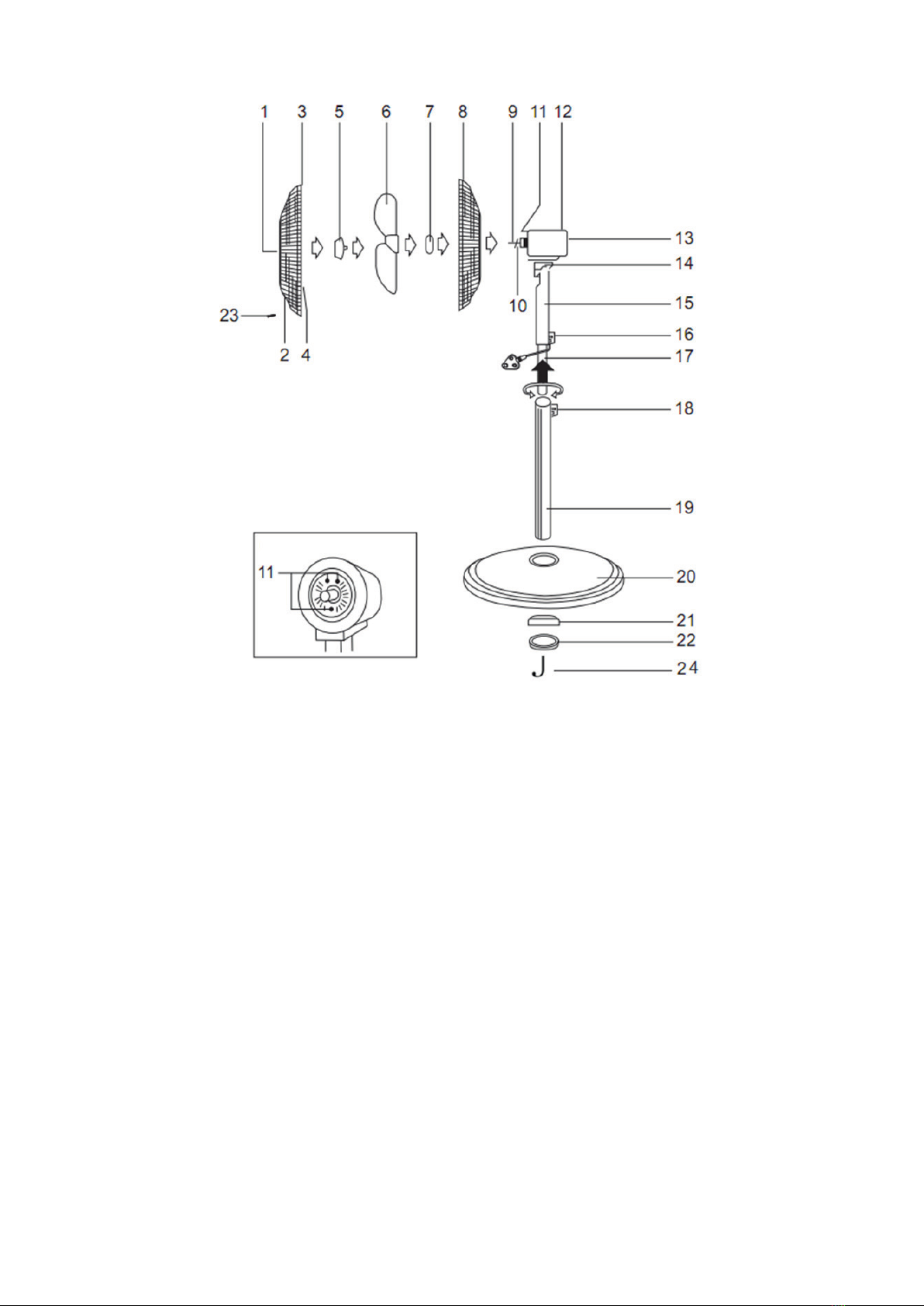
Aufbau
Nabenkappe 1 13 Fixierungsschraube des Motorgehäuses
Vorderer Korb 2 14 Gelenk zur Einstellung der Neigung
Haken 3 15 Schaltergehäuse
Fixier-Klammern 4 16 Feststellschraube
Verschlusskappe 5 17 Inneres Rohr
Rotor 6 18 Höheneinstellungsschraube
Mutter 7 19 Standrohr
Hinterer Korb 8 20 Basisplatte
Motor-Schaft 9 21 Gewicht
Motor-Schaft-Pin 10 22 Unterlegscheibe
Pins auf der Vorderseite des Motorgehäuses 11 23 Fixierschraube
Motorgehäuse 12 24 Hakenförmige Sicherheitsschraube

• Stecken Sie das Standrohr (19) in die Basisplatte (20) und kontern Sie es an der Unterseite mit dem
Gewicht (21). Verschrauben Sie mit der Hakenfömigen Sicherheitsschraube (24) und der Unterleg-
scheibe (22)
• Lösen Sie die Höheneinstellungsschraube (18), ziehen Sie das innere Rohr so weit wie gewünscht
aus und xieren Sie es, indem Sie die Schraube wieder anziehen.
• Lösen Sie die Feststellschraube (16), schieben Sie das Schaltergehäuse über das innere Rohr (17),
bis es den Stopper erreicht und ziehen Sie die Feststellschraube wieder an.
• Lösen Sie die Mutter (7), die den rückseitigen Korb am Motorgehäuse (12) hält. Bringen Sie den Korb
so wieder an, dass die drei Löcher der rückseitigen Korbhälfte auf die drei Pins (11) an der Front des
Motorgehäuses passen. Drücken Sie den Korb ein wenig an, so dass der Korb sicher xiert bleibt und
ziehen Sie die Mutter (7) wieder an.
• Entfernen Sie die Schutzfolie vom Motor-Schaft (9).
• Stecken Sie den Rotor (6) auf den Motor-Schaft (9) Richten Sie die Schlitze auf der Rückseite des Ro-
tors am Motor-Schaft-Pin (10) aus. Drücken Sie den Rotor an, so dass dieser fest auf dem Pin sitzt.
• Sichern Sie den Rotor mit der Verschlusskappe (5), die Sie GEGEN den Uhrzeigersinn festdrehen
müssen (Linksgewinde).
• Testen Sie den Sitz und die Lauähigkeit des Rotors, indem Sie ihn per Hand in Rotation versetzen.
Es sollten keine Unwucht oder Widerstände auftreten. Falls dies der Fall ist, überprüfen Sie, ob die
Befestigung am Motor-Schaft gerade und korrekt ist und nehmen Sie die Befestigung gegebenenfalls
nocheinmal vor.
• Entfernen Sie die Schutzfolie von der Nabenkappe (1).
• Önen Sie die Fixier-Klammern (4) am Rand des frontseitigen Halbkorbs (2) und lösen Sie die Fixier-
schraube (23) an der Unterseite des Front-Korbs (2).
• Positionieren Sie den Haken (3) am höchsten Punkt des hinteren Korbs (8).
• Drücken Sie den Haken nieder und drücken Sie den Rahmen des vorderen Korbs auf den des hin-
teren Korbs. Klappen Sie die Fixier-Klammern rundherum zu und bringen Sie zusätzlich noch die
Fixierschraube (23) an ihrer alten Position an.
3

Nutzungshinweise
• Verbinden Sie den Stecker mit einer Netzsteckdose.
• Nutzen Sie die ON/SPEED-Taste am Bedienteil (15), um eine der drei zur Verfügung stehenden
Geschwindigkeitsstufen „Low“, „Medium“ und „High“ zu wählen oder den Ventilator wieder auszu-
schalten.
• Drücken Sie „Swing“ für die automatische Schwenkbewegung.
• Die Timer-Funktion schaltet das Gerät nach einer wählbaren Zeitspanne (max. 7,5h) automatisch
ab (drücken Sie mehrfach auf „Timer“, um die Zeit einzustellen.
• Drei Ventilations-Modi sind wählbar durch Druck auf „Mode“.
Technische Daten
Stromversorgung: 230V AC ~ 50Hz
Maße: Höhe variabel
Ventilator-Durchmesser: ca. 41cm
Hinweise zur Entsorgung
Be ndet sich die linke Abbildung (durchgestrichene Mülltonne auf Rädern) auf dem
Produkt, gilt die Europäische Richtlinie 2012/19/EU. Diese Produkte dürfen nicht mit
dem normalen Hausmüll entsorgt werden. Informieren Sie sich über die örtlichen Re-
gelungen zur getrennten Sammlung elektrischer und elektronischer Gerätschaften.
Richten Sie sich nach den örtlichen Regelungen und entsorgen Sie Altgeräte nicht
über den Hausmüll. Durch die regelkonforme Entsorgung der Altgeräte werden Um-
welt und die Gesundheit ihrer Mitmenschen vor möglichen negativen Konsequenzen
geschützt. Materialrecycling hilft, den Verbrauch von Rohsto en zu verringern.
Konformitätserklärung
Hersteller: Chal-Tec GmbH, Wallstraße 16, 10179 Berlin.
Dieses Produkt entspricht den folgenden Europäischen Richtlinien:
2014/30/EU (EMV)
2014/35/EU (LVD)
2011/65/EU (RoHS)
206/2012/EU (ErP)
• Nutzen Sie die mitgelieferte Fernbedienung, um die Funktionen des
Ventilators bequem aus der Distanz zu steuern.
• Wechseln Sie die Batterien der Fernbedienung aus, wenn der Ventilator
nicht mehr auf die Steuerung via Fernbedienung reagiert.
4

Dear Customer,
Congratulations on purchasing this product. Please read and follow these instructions, in order to avoid
damaging the item. We do not cover any damages that may arise from improper use of the item or the
disregard of the safety instructions.
Important Safety Instructions
READ ALL INSTRUCTIONS BEFORE USING
WARNING: Keep in mind to reduce the risk of re, electrical shock, or injury to person:
• The product is for household use only.
• Connect the appliance to single-phase AC supply of the voltage specied on the rating label.
• Always turn the product to the OFF position and unplug it from the electrical outlet when not in use.
• Extreme caution is necessary when the appliance is near children, invalids or elderly person.
• Do not run cord under carpeting and do not cover cord with throw rugs, runners or the like. Arrange
cord away from trac area and where it will not be tripped over.
• Do not operate the appliance with a damaged cord or plug, or after the unit malfunctions, has been
dropped, or damaged in any manner.
• If the supply cord is damaged, it must be replaced by the manufacturer or its service agent or a si-
milarly qualied person to avoid a hazard.
• Use the appliance in a well-ventilated area. While using, distance of no less than 20cm should be kept
away from wall or corner to ensure the air intakes or exhaust openings should not be blocked unex-
pectedly. The unit must not be located immediately below or besides a curtain or the likes.
• Do not insert or allow ngers or any other objects into grill to avoid a mechanical danger when in use.
Do not block air intakes or exhaust openings in any manner.
• Use the appliance on at, dry oor only.
• This appliance can be used by children aged from 8 years and above and persons with reduced phy-
sical, sensory or mental capabilities or lack of experience and knowledge if they have been given
supervision or instruction concerning use of the appliance in a safe way and understand the hazards
involved
• cleaning and user maintenance shall not be made by children without supervision
• Children should be supervised to ensure that they do not play with the appliance.
Assembly
Centre plate 1 13 Motor housing xing screw
Front grille 2 14 Tilt adjustment
Hook 3 15 Switch housing
Fixing clip 4 16 Set knob
Locking cap 5 17 Inner pipe
Fan blade 6 18 Height adjustment screw
Rear grille securing nut 7 19 Stand pipe
Rear grille 8 20 Base
Motor shaft 9 21 Balancing weight
Shaft pin 10 22 Fixing washer
Round pins 11 23 Grille screw and nut
Motor housing 12 24 "J" shaped xing screw
5

• Insert the stand pipe (19) into the base (20) and put the balancing weight under the base and x it
tightly by turning clockwise the „J“ shaped xing screw.
• To adjust height, loosen the height adjustment screw (18). Slide the inner pipe (17) to the desired
height, and then tighten again
• Loosen the set knob (16) by turning it anti-clockwise.
• Slide the switch housing (15) down over the inner pipe (17) until it makes contact with the inner
stopper, and tighten with the set knob(16).
• Unscrew the rear grille securing nut (7) from the motor housing (13) by turning it anti-clockwise.
• Mount the rear grille (8) onto the motor housing (13) by matching the three holes on the rear grille
(8) to the three round pins (11) on the front of the motor housing (12).
• Push rmly until the pins protrude through the holes and secure the rear grille (8) to the motor
housing (12) with the rear grille securing nut (7).
• Remove the protective tube from the motor shaft (9).
• Insert the fan blade (6) onto the motor shaft (9). Align the slots on the back of the fan blade (6) to
the shaft pin (10). Press rmly until the fan blade (6) engages the shaft pin (10)
• Secure the fan blade (6) with the locking cap (5), turning anti-clockwise to tighten.
• Test the fan blade (6) operation by rotating it with your hand. There should be no friction with the
rear grille securing nut (7). If the fan blade (6) does not operate freely, disassemble and repeat the
procedure.
• Remove the protective foil from the centre cap (1)
• Open the xing clips (4) around the front grille (2) and loosen the grille screw and nut (23) at the
bottom of the front grille (2).
• Position the hook (3) on the uppermost part of the rear grille (8).
• Push the hook (3) down and press the rim of the front grille (2) onto the rear grille (8). Close all the
clips around the grille and tighten the grille screw and nut (23).
6

Operation
• Connect the plug into an electrical socket and switch on at the wall.
• You can control your stand fan either with the Remote Controller or with Control Buttons on the
control panel.
• Press the “ON/SPEED” button. At rst start-up the fan will operate at low speed.
• Press the same button to choose between Low, Medium and High speed.
• Press “SWING” button to switch on the oscillation mode.
• Press „Mode“ to select one of the 3 wind mode namely normal wind mode, natural wind mode,
sleeping wind mode.
• Press „TIMER“ to set the timing up to 7.5 hours.
Cleaning
• Switch o and unplug from the power supply before assembling or disassembling and cleaning.
• Keep the air vents at the rear of the main body free from dust or u – use a vacuum cleaner to
remove these when necessary. Do not probe any opening to remove u .
• Fan component parts should be cleaned using mild soap and a damp cloth or sponge. Do not allow
any water or other liquid to enter the motor housing.
• Thoroughly remove soap lm with clean water.
Technical Data
Power rating: 230V AC ~ 50Hz
Dimensions: Height variable; fan Ø 16“
Hints on Disposal
According to the European waste regulation 2012/19/EU this symbol on the product
or on its packaging indicates that this product may not be treated as household was-
te. Instead it should be taken to the appropriate collection point for the recycling of
electrical and electronic equipment. By ensuring this product is disposed of correct-
ly, you will help prevent potential negative consequences for the environment and
human health, which could otherwise be caused by inappropriate waste handling of
this product. For more detailled information about recycling of this product, please
contact your local council or your household waste disposal service.
Declaration of Conformity
Producer: Chal-Tec GmbH, Wallstraße 16, 10179 Berlin, Germany.
This product is conform to the following European Directives:
2014/30/EU (EMC)
2014/35/EU (LVD)
2011/65/EU (RoHS)
206/2012/EU (ErP)
• The sensor of the remote control must be pointed at the fan
receiver to operate properly.
• The distance between the remote and receiver should be no
more than 6 metres and 30 degrees radius left to right of the
fan.
7

8
Chère cliente, cher client,
Toutes nos félicitations pour l’acquisition de ce nouvel appareil. Veuillez lire attentivement les inst-
ructions suivantes de branchement et d’utilisation an d’éviter d’éventuels dommages. Le fabricant
ne saurait être tenu pour responsable des dommages dus au non-respect des consignes de sécurité
et à la mauvaise utilisation de l’appareil.
Consignes de sécurité
LISEZ INTÉGRALEMENT LES INDICATIONS AVANT D‘UTILISER L‘APPAREIL !
• Utilisez l‘appareil à domicile uniquement.
• Branchez l‘appareil sur une prise délivrant une tension de 220V à 240V tel qu‘indiqué sur la
plaque signalétique.
• Mettez toujours l‘appareil en position OFF et débranchez-le de la prise lorsque vous ne l‘utilisez
pas pendant une période prolongée.
• Ne faites pas passer le câble secteur sous un tapis et ne le recouvrez pas non plus avec un pail-
lasson, un tapis de couloir ou équivalent. N‘installez pas le câble au milieu d‘un passage mais là
où personne ne risquera de trébucher dessus.
• N‘utilisez pas l‘appareil avec un câble secteur ou une che endommagés ou après un dysfonction-
nement, par ex après qu‘il a fait une chute ou qu‘il a été endommagé de quelque manière que ce
soit.
• Si le câble secteur est endommagé adressez-vous à notre service client, ou faites changer le câble
par un spécialiste qualié ou dans un atelier.
• Utilisez l‘appareil dans un endroit bien ventilé. Pendant l‘utilisation, l‘écart entre l‘appareil et le
mur ou un coin ne doit pas être inférieur à 20cm pour que les entrées ou les sorties d‘air ne soient
pas bloquées. L‘appareil ne doit pas se trouver à proximité d‘un rideau ou équivalent.
• Pendant le fonctionnement et pour éviter tout danger, ne mettez pas vos doigts ni d‘autres objets
dans la grille. Ne bloquez pas les entrées ou sorties d‘air d‘aucune manière.
• Utilisez l‘appareil sur un sol plat et sec uniquement.
• Soyez prudent si l‘appareil est utilisé par ou en présence d‘enfants, de handicapés physiques ou de
personnes âgées. Cet appareil peut être utilisé par des personnes (enfants inclus à partir de 8 ans)
aux capacités physiques sensorielles ou mentales limitées, si elles ont été formées à l‘utilisation
de l‘appareil. Le nettoyage ne doit pas être eectué par des enfants sans surveillance.
• Surveillez les enfants, ne les laissez pas jouer avec l‘appareil.
• VEUILLEZ CONSERVER CE MODE D‘EMPLOI POUR VOUS Y RÉFÉRER ULTÉRIEUREMENT.
Montage
Capuchon de moyeu 1 13 Vis de xation du boîtier moteur
Grille avant 2 14 Articulation pour régler l'inclinaison
Crochet 3 15 Boîtier de commutateur
Pinces de xation 4 16 Vis de blocage
Bouchon de fermeture 5 17 Tube interne
Rotor 6 18 Vis de réglage en hauteur
Ecrou 7 19 Tube support
Grille arrière 8 20 Plaque de base
Axe du moteur 9 21 Poids
Goupille de l'axe moteur 10 22 Rondelle
Goupilles sur la face avant du boîtier du
moteur 11 23 Vis de blocage
Boîtier du moteur 12 24 Vis de sécurité en forme de crochet

• Insérez le tube vertical (19) dans la plaque de base (20) et contrez-le avec le poids sur la face
inférieure (21). Visser avec la vis de sécurité en forme de crochet (24) et la rondelle (22).
• Desserrez la vis de réglage de la hauteur (18), tirez le tube intérieur aussi loin que vous le souhai-
tez et xez-le en resserrant la vis.
• Desserrez la vis de blocage (16), faites glisser le boîtier de l‘interrupteur sur le tube interne (17)
jusqu‘en butée et resserrez la vis de blocage.
• Desserrez l‘écrou (7) qui maintient le panier arrière sur le carter du moteur (12). Remettez le
panier en place de manière à ce que les trois trous de la moitié arrière du panier se placent sur
les trois goupilles (11) à l‘avant du carter du moteur. Appuyez un peu sur le panier pour qu‘il soit
bien xé et resserrez l‘écrou (7).
• Retirez le lm de protection de l‘arbre du moteur (9).
• Placez le rotor (6) sur l‘arbre moteur (9) en alignant les fentes à l‘arrière du rotor avec la goupille
de l‘arbre moteur (10). Appuyez sur le rotor pour qu‘il repose fermement sur la broche.
• Fixez le rotor avec le capuchon (5) que vous devez serrer dans le sens inverse des aiguilles d‘une
montre (letage à gauche).
• Testez l‘assise et la course du rotor en le tournant à la main. Il ne devrait pas y avoir de déséqui-
libre ou de résistance. Si tel est le cas, vériez que la xation sur l‘arbre du moteur est droite et
correcte, puis rebranchez-la si nécessaire.
• Retirez le lm de protection du capuchon du moyeu (1).
• Ouvrez les clips de xation (4) sur le bord du demi-panier avant (2) et desserrez la vis de xation
(23) sur le dessous du panier avant (2).
• Positionnez le crochet (3) au point le plus haut du panier arrière (8).
• Appuyez sur le crochet et poussez le cadre du panier avant sur celui du panier arrière. Pliez les
pinces de xation tout autour et replacez également la vis de xation (23).
9

Conseils d‘utilisation
• Branchez la che dans une prise.
• Utilisez la touche ON/SPEED sur le panneau de contrôle (15), pour choisir l‘une des trois vitesses
disponibles „Low“, „Medium“ et „High“, ou pour éteindre le ventilateur.
• Appuyez sur „Swing“ pour démarrer l‘oscillation automatique.
• La fonction timer éteint l‘appareil automatiquement au bout d‘une durée déterminée (max. 7,5h)
(appuyez plusieurs fois sur „Timer“, pour régler la durée.)
• Trois modes de ventilation sont disponibles en appuyant sur „Mode“.
Fiche technique
Alimentation : 230V AC ~ 50Hz
Dimensions : hauteur variable
Diamètre du ventilateur: env. 41cm
Conseils pour le recyclage
Le pictogramme ci-contre apposé sur le produit signi e que la directive européenne
2012/19/UE s‘applique (poubelle à roues barrée d’une croix). Ces produits ne peuvent
être jetés dans les poubelles domestiques courantes. Renseignez-vous concernant les
règles appliquées pour la collecte d’appareils électriques et électroniques. Conformez-
vous aux réglementations locales et ne jetez pas vos anciens produits avec les ordures
ménagères. Le respect des règles de recyclage des vieux produits aide à la protection
de l’environnement et de la santé de votre entourage contre les conséquences négatives
possibles. Le recyclage des matériaux aide à réduire l’utilisation des matières premières.
Déclaration de conformité
Fabricant: Chal-Tec GmbH, Wallstraße 16, 10179 Berlin.
Ce produit est conforme aux directives européennes suivantes :
2014/30/UE (CEM)
2014/35/UE (LVD)
2011/65/UE (RoHS)
206/2012/UE (ErP)
• Utilisez la télécommande fournie pour piloter confortablement les fon-
ctions du ventilateur à distance.
• Remplacez les piles de la télécommande si le ventilateur ne réagit plus
aux commandes de celle-ci.
10
Table of contents
Languages:
Other oneConcept Fan manuals

oneConcept
oneConcept Hightower 2G User manual

oneConcept
oneConcept 10030093 User manual

oneConcept
oneConcept 10031517 User manual

oneConcept
oneConcept 10029726 User manual

oneConcept
oneConcept 10029282 User manual

oneConcept
oneConcept 10029509 User manual

oneConcept
oneConcept 10028199 User manual

oneConcept
oneConcept 10032583 User manual

oneConcept
oneConcept 10031517 User manual

oneConcept
oneConcept 10029730 User manual