manuals.online logo
Brands
  1. Home
  2. •
  3. Brands
  4. •
  5. Opitec
  6. •
  7. Toy
  8. •
  9. Opitec Hobbyfix User manual

Opitec Hobbyfix User manual

1
E109771#1
109.771
Parts List
Quantity Size in mm Part No.
Boat hull 1 1
Plywood 1 300x135x3 2
Welding rod 2 250x3 3
Black cable 1 500 4
Battery holder 1 5
Machine screw 2 3x8 6
Solarmotor 1 7
Electro board 1 ca. 25x23 8
Machine screw 2 3x8 9
Machine screw 2 3x20 10
Machine screw 2 2x6 11
Machine screw 4 3x6 12
Nuts 12 M3 13
Washers 6 7/3,2 14
Connection block 7 15
Grub screw 2 M3x6 16
Nails 2 20 17
Screw eye 2 12 18
Worm 1 19
Double gear ,red 3 50/10 20
Distance disc, white 2 2,9 21
Necessary Tools
Pillar drill
Machine vice
Wood drills 1 &3mm dia.
Metal drill 2mm
Screwdriver
Fine saw
Soldering iron
Metal cutters
2 component glue
Wood glue
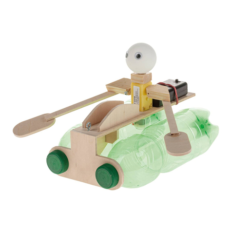
Boat with mechanical rower
Please Note
The OPITEC range of projects is
not intended as play toys for
young children.They are tea-
ching aids for young people
learning the skills of Craft, De-
sign and Technolo- gy.These
projects should only be under-
taken and tested with the
guidance of a fully qualified
adult. The finished projects are
not suitable to give to children
under 3 years old. Some parts
can be swallowed. Dan- ger of
suffocation!
2E109771#1
INSTRUCTIONS
Photo 4
4. Mark the copper tracks on the electro
board (see pattern on page 11)
for drilling and the slot. Photo 4
5. Hold the electro board carefully in a
machine vice and carefully drill the
holes ( see pattern on page 5)
Important!
Too much pressure can snap the board
in two!!!
6. Use a ne metal working saw to remo-
ve the slot marked on the board. Then
nally mark out and saw the board to
the correct size ( see pattern on page
11) Work carefully as it is easy to break
the board at this stage
Photo 5
Photo 6
Photo 7 Photo 8 Photo 9
Photo 1
1. Mark out on the welding rod (3) the
following measurements, one piece 2
x35mm, one piece 1x30mm and one
1x50mm
2. On the second welding rod mark out 2
x 95mm long pieces
3. Use a pair of metal bolt cutters to cut
the welding rod in the marked places
Photo 3
Remove any sharp ends with a le
Photo 2 Photo 3
7. Slide the worm gear on the motor
shaft. Slide it on so that the end of the
shaft is at the end of the gear.
8. Place the electro board over the worm
gear so that the 7mm hole in the board
locates on the motor
9. Fix the board to the motor using a ma-
chine screw (11 )and two washers (14)
as shown in photo 9
3
E109771#1
INSTRUCTIONS
Photo 10 Photo12
Photo 13
10. Insert a machine screw (6) from the
rear through the 3mm hole in the
electro board and the add a nut (13) .
Once this is in place do the same with
the second hole Photo 10
12. Place a connecter over each of the
machine screws as shown. Leave
about 1mm gap then lightly tighten
the side holding screw (12)
13. Take a double gear (20) and saw o
the small gear. To do this place the
gear vertically in
a vice.
Note !
try not to damage the plastic teeth in
the vice
14. Mount the gear in between in the
middle hole in two connector blocks
using the 50mm welding rod as
shown. Make sure that the axle is in a
central position and the gear engages
with the worm
Photo 14
Note:
The gear must engage freely with the
worm drive and not stick as it turns
15. Carefully saw out the shape of the
gear (20) as shown in the pattern (
page11) To do this rst mark them
out , then enlarge the middle hole to
4mm dia . Finally saw / le the shape
as shown in the pattern. Repeat this
process with the second gear
16. Slide the sawn out gears on the ends
of the 50mm axle as shown and test
the running action
The gears should engage easily and
turn quietly when rotating the axle.
Adjust if necessary
Photo 16
17. Cut the seat for the boat from the
plywood sheet (2)
and trim it to t. Use the two compo-
nent glue to t the
the seat in position ( see pattern on
page 6)
Note!
Use the pattern for the correct size !
18. Glue in place the 35mm and the
30mm pieces of welding rod in a an
upright position as shown in the
pattern on page 9, see photo 18.
Use 2 component glue
35mm
30mm
Photo 18
Note:
It can take up to 20 minutes for the
glue to harden
depending on the make
Photo 17
Photo 15
11. Drill the centre holes in the 2 connec-
ters out 3mm diameter. (see photo
11)
Photo 11
4E109771#1
16
a
b
d
d
e
e
f
f
g
g
c
INSTRUCTIONS
21. As shown insert the handle of the oar
through the connector block and carefully
tighten the screw 12
The whole arrangement should work freely
in a rowing movement
Photo 22
22. Once the oar works easily slide
on a distance piece (20) as
shown in the photo 22
20. Take a connector block and insert a grub screw (16) so that a max of
2mm protrudes ( use instant glue) Screw the free end of the grub screw
in a second connector block so that this can just about turn Diagram 20
Photo 21
Photo 20
23. Bring the connectors in the correct
position : Between the distance pie-
ces and the connector block should
be about 10mm
Finally tighten the connector blocks
Photo 23
Photo 23
27. Lay both of the forearms on a
board in a mirror image next to
each other . Using 2 component
glue a screw eye (18) in the slot
on each end to make a hand
So that the screw eye is not twis-
ted place a piece of scrap under
the eye
Photo 27
Photo 26
26. Use the plywood sheet (2) to make the
rower. Trace the parts of the rower on the
wood (Pattern on page 7) Use a fretsaw and
then sand all the edges. Drill all the holes
as shown It is best to drill all the holes rst
and then saw out the individual parts
Photo 28
28. Join the parts of the arm ( f+g)
with the nails (16) in the pre-
drilled holes
Carefully snip o the protruding
points of the nails leaving about
4-5mm standing up
Note
For a functioning rowing
action it is not necessary
to
to make the rowing gure.
If you wish this can be
made at a later date
Before assembling the
rower it better to have all
the parts painted and de-
corated . We recommend
using any Acrylic paints
19.Saw out the blades for the oars, see
patterns
Coat the free ends of the wire ( blades
/ 95mm ) with 2 component glue and
then mount the blades on the wires
Photo 19
Photo 25a Photo 25b
25. Mark and saw out the rudder, see pattern on
Page 7
Fix the connector block with 2 screws (9) The
top screw has 2 washers before the nut (14)
The washers act as a xing clamp for the wire
handle
Photo 24
24.The parts for the boat stand are made
up from the plywood sheet (2) Saw
them out and sand the edges
Patterns can be found on page 7
Assemble and glue the parts to-
gether as shown
5
E109771#1
35. Place the mechanism in the boat so that it can be glued in place. It is to note that the oars
are placed so that they make a line with the drive shaft and that the oars in a straight line
and in a vertical position. ( 12 ‘oclock) ( see diagram 35a+35b)
Place the oars in the rowlocks .(This is easiest when the oars are in the 9 o’clock postion)
If this is not possible the rowlock connectors need to be loosened and adjusted
Photo 35a
Photo 35b
Note
The direction of the mechanism
INSTRUCTIONS
33. Glue the two halves of the body (e)
together with the arms mounted in
position
34. Glue the two halves of the head
together ( part a) on to the body
(part b)
Photo 30
b
g
f
f
g
e
e
Photo 33
30. Add a nut (13) and screw it tight
Photo 34
Photo 31
Photo 32
31. Then add another two nuts (13) and
assemble the arm (f+g) Leave about a
space of about 3mm between the rst
nut and second pair
32. Then add 2 washers (12) to the arm
(f+g) so that it can move easily . Make
up the second arm the same way in a
mirror image Photo 32
29. Insert a machine screw 10
through the hole in part e
Photo 29
6E109771#1
INSTRUCTIONS
36. Glue the rower on the seat as shown so
that he sits directly on the mechanism
37. The oars go rst through the hand (
Screw eye ) then in the sawn gear, see
photo
Photo 36
Photo 37
39. Cut 2pieces x100mm from the cable
(4) and remove the insulation from the
ends ( ca 5mm ) Solder one cable to
one end of the battery holder and an
end of the other cable to the opposite
end of the battery holder.
The free cable ends can now be xed
to the tabs on the solar motor Photo
39
Photo 39
40.When a 1.5volt battery is inserted the mechanism should turn the oars and arms
in a circular motion. Should the arm movement jam or be sti check the joints
and adjust them until they move freely
Photo 38
38. Slide the connector block on the
wire for the oars (35mm ) so that the
handle of the oar cannot slide out of
the screw eye and gear ( see photo
36) Carry out the same technique
with the second oar
7
E109771#1
110
35
100
35
160
12
Pattern for the rower + wooden
parts
d
d
e
e
c
a
b
h
g
g
ff
a
ø1,0mm
ø3,0mm
ø3,0mm
Pattern for the stand
8E109771#1
9
E109771#1
12
121
130
6
Pattern for the boat hull
10 E109771#1
11
E109771#1
135
300
Pattern for the gear
Pattern for the holed board
ø 4,0
Cutting pattern for the plywood
M 1:2
Saw roughly to shape rst

Other Opitec Toy manuals

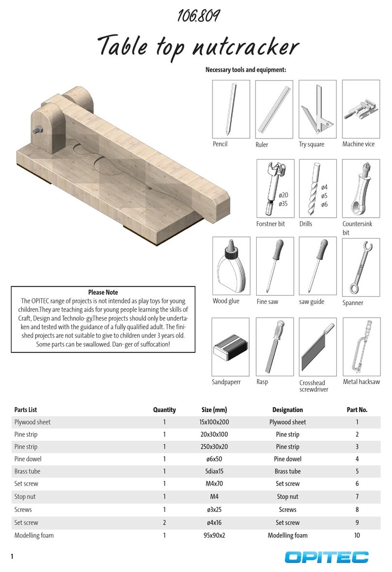
Opitec 106.809 User manual

Opitec

Opitec 106.809 User manual

Opitec 115.305 User manual

Opitec

Opitec 115.305 User manual

Opitec Windflyer II User manual

Opitec

Opitec Windflyer II User manual

Opitec Wasp User manual

Opitec

Opitec Wasp User manual

Opitec Hobbyfix 113.727 User manual

Opitec

Opitec Hobbyfix 113.727 User manual

Opitec Hobbyfix Flip User manual

Opitec

Opitec Hobbyfix Flip User manual

Opitec Floating Ball User manual

Opitec

Opitec Floating Ball User manual

Opitec 111.714 User manual

Opitec

Opitec 111.714 User manual

Opitec 113.141 User manual

Opitec

Opitec 113.141 User manual

Opitec Rattle Snake User manual

Opitec

Opitec Rattle Snake User manual

Opitec Hobbyfix Cloud User manual

Opitec

Opitec Hobbyfix Cloud User manual

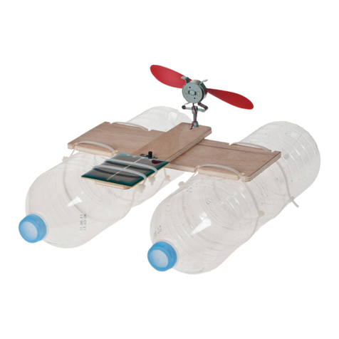
Opitec Recycling Rowing Boat User manual

Opitec

Opitec Recycling Rowing Boat User manual

Opitec Easy-Line Wind Generator User manual

Opitec

Opitec Easy-Line Wind Generator User manual

Opitec 112.994 User manual

Opitec

Opitec 112.994 User manual
Opitec 116415 User manual

Opitec

Opitec 116415 User manual

Opitec Hobbyfix 101.706 User manual

Opitec

Opitec Hobbyfix 101.706 User manual

Opitec 102.320 Nummer II User manual

Opitec

Opitec 102.320 Nummer II User manual

Opitec 114.033 User manual

Opitec

Opitec 114.033 User manual

Opitec Running worker with wheelbarrow User manual

Opitec

Opitec Running worker with wheelbarrow User manual

Opitec Hobbyfix Stiletto 105.755 User manual

Opitec

Opitec Hobbyfix Stiletto 105.755 User manual

Opitec MANITOU 101.200 User manual

Opitec

Opitec MANITOU 101.200 User manual

Opitec 120.852 User manual

Opitec

Opitec 120.852 User manual
Opitec 117167 User manual

Opitec

Opitec 117167 User manual

Opitec Hobbyfix Cube User manual

Opitec

Opitec Hobbyfix Cube User manual

Popular Toy manuals by other brands

Enabling Devices Let Loose Lenny user guide

Enabling Devices

Enabling Devices Let Loose Lenny user guide

Eduard Su-76M Assembly instructions

Eduard

Eduard Su-76M Assembly instructions

NOCH LASER CUT minis 67135 manual

NOCH

NOCH LASER CUT minis 67135 manual

Mattel Barbie K8079 instructions

Mattel

Mattel Barbie K8079 instructions

Fisher-Price Baby Smartronics Roll-Along Turtle 71667 quick start guide

Fisher-Price

Fisher-Price Baby Smartronics Roll-Along Turtle 71667 quick start guide

Horizon Hobby Radian instruction manual

Horizon Hobby

Horizon Hobby Radian instruction manual

LEGO Friends 41009 instruction manual

LEGO

LEGO Friends 41009 instruction manual

Faller 587 manual

Faller

Faller 587 manual

Magformers POWER GEAR SET Assembly instructions

Magformers

Magformers POWER GEAR SET Assembly instructions

MTHTrains Premier SD90 Operator's manual

MTHTrains

MTHTrains Premier SD90 Operator's manual

Eduard 32 556 Assembly instructions

Eduard

Eduard 32 556 Assembly instructions

Kenner ATRC instructions

Kenner

Kenner ATRC instructions

Fisher-Price N7121 instruction sheet

Fisher-Price

Fisher-Price N7121 instruction sheet

Miniature Aircraft USA Fury 57 X-Cell manual

Miniature Aircraft USA

Miniature Aircraft USA Fury 57 X-Cell manual

Zapf Creation BABY Born 826898 manual

Zapf Creation

Zapf Creation BABY Born 826898 manual

Play-Doh E7776 manual

Play-Doh

Play-Doh E7776 manual

Mattel V9233 instructions

Mattel

Mattel V9233 instructions

BNF Blade 270 CFX instruction manual

BNF

BNF Blade 270 CFX instruction manual

manuals.online logo
manuals.online logoBrands
  • About & Mission
  • Contact us
  • Privacy Policy
  • Terms and Conditions

Copyright 2025 Manuals.Online. All Rights Reserved.