9
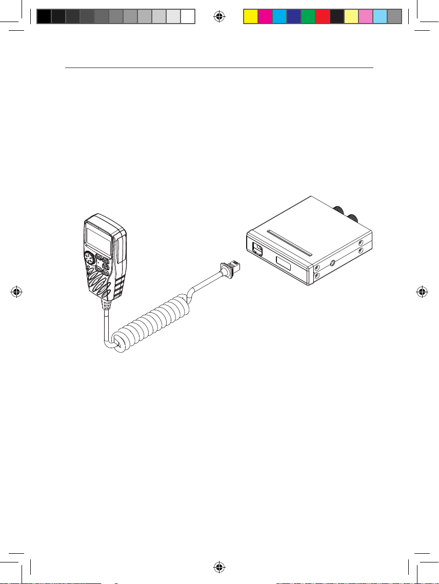
Installation of your Oricom Radio
CAUTION
This radio is designed for operation on a 12 Volt battery
system. It should not be connected directly to a 24 Volt
system.
When installing your radio in your vehicle, check that
during installation you do not damage any wiring or vehicle
components that may be hidden around the mounting
position.
Ensure the installation does not interfere with the operation of
the vehicle and meets all regulatory and safety retirements for
accessories tted to your vehicle.
For optimum performance, your radio needs to be installed
correctly. If you are unsure about how to install your radio, we
suggest you have your radio professionally installed by a UHF
specialist or Auto electrician. When installing the radio, avoid
mounting it close to heaters or air conditioners. Never press
the PTT button before connecting the antenna to the radio.
Wiring Methods
There are two possible wiring congurations for connecting to the
vehicles power supply.
A. Radio stays ON when the ignition is switched OFF
Connect the radio’s negative (black) lead to the vehicle chassis, or
directly to the battery’s negative terminal.
Connect the radio’s positive (red) lead via the 3 Amp fuse to the
battery’s positive terminal. Alternatively, the positive lead could be
connected at the fuse box at a point that has DC Power continuously
available (preferably the battery side of the ignition switch) via the 3
Amp fuse.
B. Radio turns OFF with the ignition switch
Connect the radio’s negative (black) lead to the vehicle’s chassis, or
directly to the battery’s negative terminal.
OR019523 - UHF182X user manual_09-17-20.indd 9 2020/9/17 11:22:46