manuals.online logo
Brands
  1. Home
  2. •
  3. Brands
  4. •
  5. Oriental motor
  6. •
  7. Engine
  8. •
  9. Oriental motor PK Series User manual

Oriental motor PK Series User manual

HM-7410-18
取扱説明書
2 相ステッピングモーター
PK シリーズ 高トルクタイプ
お買い上げいただきありがとうございます。
この取扱説明書には、製品の取り扱いかたや安全上の注意事項を示し
ています。
• 取扱説明書をよくお読みになり、製品を安全にお使いください。
• お読みになったあとは、いつでも見られるところに必ず保管してください。
はじめに
 お使いになる前に
製品の取り扱いは、適切な資格を有する人が行なってください。
お使いになる前に、「安全上のご注意」をよくお読みのうえ、正しくお使いく
ださい。
この製品は、一般的な産業機器の機器組み込み用として設計されています。
その他の用途には使用しないでください。また、電源には、一次側と二次側
が強化絶縁された直流電源を使用してください。この警告を無視した結果
生じた損害の補償については、当社は一切その責任を負いませんので、あ
らかじめご了承ください。
 有害物質
RoHS(EU 指令 2002/95/EC 27Jan.2003)適合
安全上のご注意
ここに示した注意事項は、製品を安全に正しくお使いいただき、お客様や
他の人々への危害や損傷を未然に防止するためのものです。内容をよく理
解してから製品をお使いください。
⼊๔
この警告事項に反した取り扱いをすると、死亡または重傷を負う場合がある
内容を示しています。
• 爆発性雰囲気、引火性ガスの雰囲気、腐食性の雰囲気、水のかかる場
所、可燃物のそばでは使用しないでください。火災・けがの原因になりま
す。
• 設置、接続、運転・操作、点検・故障診断の作業は、適切な資格を有す
る人が行なってください。火災・けがの原因になります。
• 昇降装置に使用するときは、可動部の位置保持対策を行なってください。
モーターは電源が OFF の時、保持力がなくなるため、可動部が落下して
けが・装置破損の原因になります。
• モーターは筐体内に設置してください。けがの原因になります。
• 電源入力電圧は、定格範囲を必ず守ってください。火災の原因になりま
す。
• 接続図にもとづき、確実に接続してください。火災の原因になります。
• コネクタ部を無理に曲げたり、押さないでください。火災の原因になりま
す。
• モーターリード線を無理に曲げたり、引っ張ったり、挟み込まないでくださ
い。火災の原因になります。
• 電源には、一次側と二次側が強化絶縁された直流電源を使用してくださ
い。感電の原因になります。
• 停電したときは、電源を切ってください。停電復旧時にモーターが突然起
動して、けが・装置破損の原因になります。
• モーターを分解・改造しないでください。けがの原因になります。内部の
点検や修理は、お買い上げになった支店または営業所に連絡してくださ
い。
ᵈᗧ
この注意事項に反した取り扱いをすると、傷害を負うまたは物的損害が発生
する場合がある内容を示しています。
• モーターの仕様値を超えて使用しないでください。けが・装置破損の原
因になります。
• 運転中および停止後しばらくの間は、モーターに触れないでください。
モーターの表面が高温のため、やけどの原因になります。
• モーター出力軸、モーターリード線を持たないでください。けがの原因に
なります。
• 装置の故障や動作の異常が発生したときは、装置全体が安全な方向へ
はたらくよう非常停止装置、または非常停止回路を外部に設置してくださ
い。けがの原因になります。
• 絶縁抵抗測定、絶縁耐圧試験は、モーターとドライバそれぞれで行なっ
てください。モーターとドライバを接続した状態で、絶縁抵抗測定、絶縁
耐圧試験を行なうと、製品が破損するおそれがあります。
• 運転中は回転部(出力軸)に触れないでください。けがの原因になりま
す。
• 異常が発生したときは、ただちに運転を停止して、ドライバの電源を切っ
てください。火災・けがの原因になります。
• モーターを廃棄するときは、できるだけ分解し、産業廃棄物として処理し
てください。
製品の確認
次のものがすべて揃っていることを確認してください。製品が正しいか、製
品の銘板に記載された品名で確認してください。不足したり破損している場
合は、お買い求めの支店・営業所までご連絡ください。
• モーター ............................................ 1 台
• コネクタ付リード線(0.6 m)............... 1 本(PK2-L のみ)
∗ には、モーターの種類を表わす英数字が入ります。
• 取扱説明書(本書)........................... 1 部
設 置
 設置場所
モーターは機器組み込み用に設計・製造されています。風通しがよく、点検
が容易な次のような場所に設置してください。
• 屋内に設置された筐体内(換気口を設けてください)
• 使用周囲温度 −10~+50 °C(凍結しないこと)
• 使用周囲湿度 85%以下(結露しないこと)
• 爆発性雰囲気、有害なガス(硫化ガスなど)、および液体のないところ
• 直射日光が当たらないところ
• 塵埃や鉄粉などの少ないところ
• 水(雨や水滴)、油(油滴)、およびその他の液体がかからないところ
• 塩分の少ないところ
• 連続的な振動や過度の衝撃が加わらないところ
• 電磁ノイズ(溶接機、動力機器など)が少ないところ
• 放射性物質や磁場がなく、真空でないところ
 設置方法
モーターは耐振動性にすぐれ、熱伝導効果が高い平滑な金属板に設置し
てください。モーターを設置するときは 4か所の取付穴を使用して、金属板
との間にすき間がないように、4本のボルト(付属していません)で固定してく
ださい。
ขઃⓣ
䉟䊮䊨䊷ฃ䈔
㩿ᐳ䈓䉍䉁䈢䈲⽾ㅢⓣ㪀
㊄ዻ᧼
㊄ዻ᧼
ขઃⓣ
䉟䊮䊨䊷ฃ䈔
㩿ᐳ䈓䉍䉁䈢䈲⽾ㅢⓣ㪀
⸳⟎ᣇᴺA⸳⟎ᣇᴺB
モーター
タイプ∗ボルトの呼び 締付トルク
(N·m)
有効ねじ
深さ(mm)設置方法
PK21PM2 P0.4 0.25 2.5
PK22PM2.5 P0.45 0.5 2.5
PK23P
PK24PM3 P0.5 1 4.5
A
PK26P M4 2 −B
∗ には、モーターの長さを表わす数字が入ります。
 許容オーバーハング荷重と許容スラスト荷重
モーター出力軸にかかるオーバーハング荷重は、下表の許容値を超えない
でください。スラスト荷重は、使用するモーターの質量を超えないでください。
許容オーバーハング荷重(N)
モーター出力軸先端からの距離
モーター
タイプ∗0 mm 5 mm 10 mm 15 mm 20 mm
PK21P12 15 −−−
PK22P25 34 52 −−
PK23P
PK24P20 25 34 52 −
PK26P 61 73 90 110 160
PK26PA 49 60 79 110 −
∗ には、モーターの長さを表わす数字が入ります。
には、A(片軸)または B(両軸)が入ります。
 負荷の取り付け
負荷をモーターに取り付けるときは、モーター出力軸と負荷の軸中心線を
揃えてください。カップリングやプーリーをモーター出力軸に取り付けるとき
は、出力軸や軸受けに損傷を与えないでください。
接 続
重要 • モーターリード線を固定して、屈曲や自重によるストレスが接
続部に加わらないようにしてください。モーターリード線の曲率
半径は、できるだけ大きくしてください。
• PK21Pはコネクタ接続方式ではありません。
• PK22P、PK23P、PK24P、PK26Pのモーターリード線
を外すときは、出力軸方向へ水平に外してください。
• PK23P、PK24P、PK26Pのモーターリード線は、ロック
機能付コネクタを採用しています。コネクタを取り外すときは、
ロックを解除してください。コネクタがロックされたまま強い力
で引き抜くと、モーターが破損する原因になります。
 PK21P
モーターは結線図にしたがって接続してください。
結線図
㤥
✛
A
⿒㕍
B
5ᧄ䊥䊷䊄✢䉺䉟䊒
ᯍ
㤥
✛
4ᧄ䊥䊷䊄✢䉺䉟䊒
⿒㕍
B
AA
B
 PK22P、PK23P、PK24P、PK26P
PK22P、PK23P、PK24P、PK26Pは、コネクタ接続方式です。
コネクタピン番号を確認し接続してください。
䋨4䋩㤥
䋨5䋩㤛
䋨6䋩✛
A
⿒
䋨3䋩
⊕
䋨2䋩
㕍
䋨1䋩
B
6ᧄ䊥䊷䊄✢䉺䉟䊒
䋨4䋩㤥
䋨6䋩✛
4ᧄ䊥䊷䊄✢䉺䉟䊒
⿒
䋨3䋩
㕍
䋨1䋩
B
A
⚿✢࿑ 䊏䊮㈩೉࿑
䋨6䋩䋨5䋩䋨4䋩䋨3䋩䋨2䋩䋨1䋩
䋨䋩䊏䊮⇟ภ
A
B
図のリード線色は、付属またはオプションのコネクタ付リード線を使った場合
です。コネクタセットを使う場合やお客様がコネクタ、リード線を用意する場
合は、図のピン番号で接続してください。
4本リード線タイプは、ピン番号(2)と(5)は使用しません。
 適合コネクタ・リード線
適合コネクタ、リード線は下表のとおりです。
モーター
タイプ
ハウジング
コンタクト
(molex)
リード線 圧着工具
(molex)
PK22P51065-0600
50212-8XXX
AWG30~24
(0.05~0.2 mm2)
被覆外径 Ø1.4 mm 以下
ストリップ長さ 1.3~1.8 mm
57176-5000
PK23P
PK24P
51103-0600
50351-8XXX
AWG28~22
(0.08~0.3 mm2)
被覆外径 Ø1.15~1.8 mm
ストリップ長さ 2.3~2.8 mm
57295-5000
PK26P51067-0600
50217-9XXX
AWG24~18
(0.2~0.75 mm2)
被覆外径 Ø1.4~3 mm
ストリップ長さ 3~3.5 mm
57189-5000
57190-5000
∗ オプション(別売)でコネクタセット、コネクタ付リード線を用意しています。
点 検
モーターの運転後は、定期的に次の項目について点検することをおすすめ
します。異常があるときは使用を中止し、お客様ご相談センターにお問い合
わせください。
• モーター軸受部(ボールベアリング)などから異常な音が発生していない
か。
• コネクタの接続部に緩みがないか、モーターリード線に傷、ストレスがない
か。
• モーター出力軸と負荷軸に心ズレが出ていないか。
• この取扱説明書の一部または全部を無断で転載、複製することは、禁
止されています。
• 取扱説明書に記載されている情報、回路、機器、および装置の利用
に関して産業財産権上の問題が生じても、当社は一切の責任を負い
ません。
• 製品の性能、仕様および外観は改良のため予告なく変更することがあ
りますのでご了承ください。
• 取扱説明書には正確な情報を記載するよう努めていますが、万一ご
不審な点や誤り、記載もれなどにお気づきの点がありましたら、最寄り
のお客様ご相談センターまでご連絡ください。
• は、日本その他の国におけるオリエンタルモーター
株式会社の登録商標または商標です。
© Copyright ORIENTAL MOTOR CO., LTD. 2011
䈖䈱ขᛒ⺑᣿ᦠ䈲ౣ↢⚕䉕૶↪䈚䈩䈇䉁䈜䇯
http://www.orientalmotor.co.jp/
䃂㩷⵾ຠ䈮䈧䈇䈩䈱䈗⾰໧䇮䈗⋧⺣䈲䈍ቴ᭽䈗⋧⺣䉶䊮䉺䊷䈻䈍໧䈇ว䉒䈞䈒䈣䈘䈇䇯
㩷 䊐䊥䊷䉮䊷䊦䋨ήᢱ䋩䈪䈜䇯៤Ꮺ㔚⹤䊶PHS䈎䉌䉅䈗೑↪䈏น⢻䈪䈜䇯
㩷 ฃઃᤨ㑆㩷 ᐔᣣ㩷 8:00䌾20:00
㩷 㩷 ࿯ᦐᣣ㩷 9:00䌾17:30
᧲㩷 㩷 TEL 0120-925-410 FAX 0120-925-601
ฬฎደ㩷 TEL 0120-925-420 FAX 0120-925-602
ᄢ㩷 㒋㩷 TEL 0120-925-430 FAX 0120-925-603
HM-7410-18
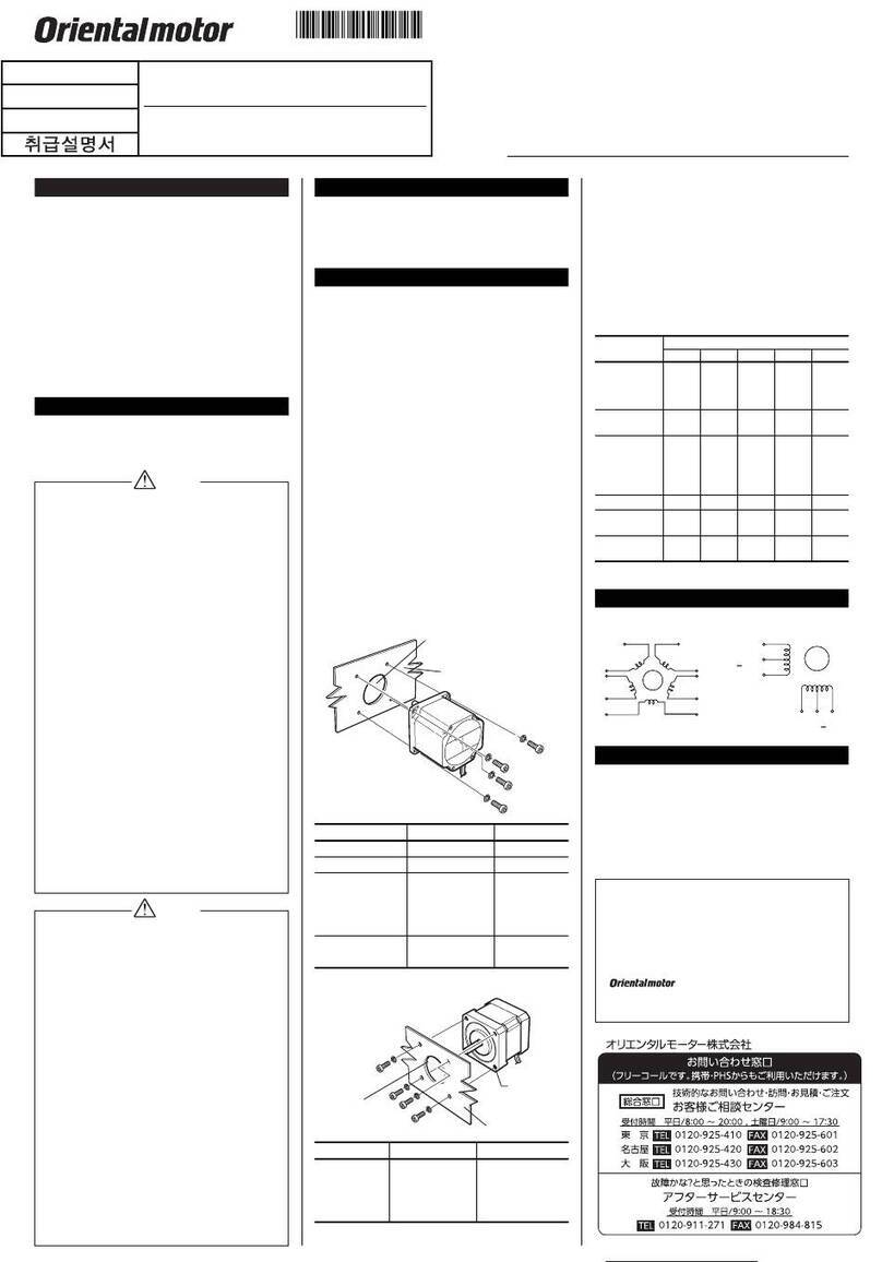
OPERATING MANUAL
2-Phase Stepping Motor
PK Series High Torque Type
Thank you for purchasing an Oriental Motor product.
This Operating Manual describes product handling procedures and
safety precautions.
• Please read it thoroughly to ensure safe operation.
• Always keep the manual where it is readily available.
Introduction

Before using the motor
Only qualified personnel should work with the product.
Use the product correctly after thoroughly reading the section “Safety
precautions”.
The product described in this manual has been designed and manufactured
for use in general industrial machinery, and must not be used for any other
purpose. For the power supply use a DC power supply with reinforced
insulation on its primary and secondary sides. Oriental Motor Co., Ltd. is not
responsible for any damage caused through failure to observe this warning.

Hazardous substances
RoHS (Directive 2002/95/EC 27Jan.2003) compliant
Safety precautions
The precautions described below are intended to prevent danger or injury to
the user and other personnel through safe, correct use of the product. Use the
product only after carefully reading and fully understanding these
instructions.
Warning
Handling the product without observing the instructions that accompany a
“Warning” symbol may result in serious injury or death.
• Do not use the product in explosive or corrosive environments, in the
presence of flammable gases, locations subjected to splashing water, or
near combustibles. Doing so may result in fire or injury.
• Assign qualified personnel the task of installing, wiring,
operating/controlling, inspecting and troubleshooting the product. Failure
to do so may result in fire or injury.
• Provide a means to hold moving parts in place for applications involving
vertical travel. The motor loses holding torque when the power is shut off,
allowing the moving parts to fall and possibly causing injury or damage to
equipment.
• Install the motor in an enclosure in order to prevent injury.
• Keep the input-power voltage within the specified range to avoid fire.
• Connect the motor lead wires securely according to the wiring diagram in
order to prevent fire.
• Do not forcibly bend or push the connector. Doing so may fire.
• Do not forcibly bend, pull or pinch the motor lead wire. Doing so may fire.
• For the power supply use a DC power supply with reinforced insulation on
its primary and secondary sides. Failure to do so may result in electric
shock.
• Turn off the power in the event of a power failure, or the motor will
suddenly start when the power is restored and may cause injury or damage
to equipment.
• Do not disassemble or modify the motor. This may cause injury. Refer all
such internal inspections and repairs to the branch or sales office from
which you purchased the product.
Caution
Handling the product without observing the instructions that accompany a
“Caution” symbol may result in injury or property damage.
• Do not use the motor beyond its specifications, or injury or damage to
equipment may result.
• Do not touch the motor during operation or immediately after stopping.
The surface is hot and may cause a skin burn(s).
• Do not hold the motor output shaft or motor lead wire. This may cause
injury.
• Provide an emergency-stop device or emergency-stop circuit external to
the equipment so that the entire equipment will operate safely in the event
of a system failure or malfunction. Failure to do so may result in injury.
• Conduct the insulation resistance measurement or withstand voltage test
separately on the motor and the driver. Conducting the insulation
resistance measurement or withstand voltage test with the motor and driver
connected may result in injury or damage to equipment.
• To prevent bodily injury, do not touch the rotating parts (output shaft) of
the motor during operation.
• Immediately when trouble has occurred, stop running and turn off the
driver power. Failure to do so may result in fire or injury.
• To dispose of the motor, disassemble it into parts and components as much
as possible and dispose of individual parts/components as industrial waste.
Checking the product
Confirm that all of the following items are available. To verify that the unit
you’ve purchased is the correct one, check the model number shown on the
nameplate. Should you find any item missing or damaged, contact the
Oriental Motor sales office where you purchased the product.
• Motor ................................................. 1 unit
• Connector lead [0.6 m (2 ft.)] ........... 1 pc. (PK2-L only)
∗ represents an alpha numeric indicating the motor type.
• Operating manual (this manual)........ 1 copy
Installation

Location for installation
The motor is designed and manufactured for installation in equipment.
Install it in a well-ventilated location that provides easy access for inspection.
The location must also satisfy the following conditions:
• Inside an enclosure that is installed indoors (provide vent holes)
• Operating ambient temperature –10 to +50 °C (+14 to +122 °F)
(non-freezing)
• Operating ambient humidity 85% or less (non-condensing)
• Area that is free of explosive atmosphere or toxic gas (such as sulfuric gas)
or liquid
• Area not exposed to direct sun
• Area free of excessive amount of dust, iron particles or the like
• Area not subject to splashing water (rain, water droplets), oil (oil droplets)
or other liquids
• Area free of excessive salt
• Area not subject to continuous vibration or excessive shocks
• Area free of excessive electromagnetic noise (from welders, power
machinery, etc.)
• Area free of radioactive materials, magnetic fields or vacuum

How to install the motor
Install the motor onto an appropriate flat metal plate having excellent
vibration resistance and heat conductivity. When installing the motor, secure
it with four bolts (not supplied) through the four mounting holes provided.
Leave no gap between the motor and plate.
Mounting
hole
Mounting-pilot holder
(countersunk or drilled through)
Metal plate
Mounting
hole
Mounting-pilot holder
(countersunk or drilled through)
Metal plate
Installation method A Installation method B
Motor
type Bolt size
Tightening
torque
[N·m (lb-in)]
Effective
depth
[mm (in.)]
Installation
method
PK21P M2 P0.4 0.25 (2.2) 2.5 (0.1)
PK22PM2.5 P0.45 0.5 (4.4) 2.5 (0.1)
PK23P
PK24PM3 P0.5 1 (8.8) 4.5 (0.18)
A
PK26P M4 2 (17.7) −B
∗ Enter the motor length in the box () within the model number.

Permissible overhung load and permissible thrust load
The overhung load on the motor’s output shaft or gear output shaft must be
kept within the permissible values listed below. The thrust load must not
exceed the motor’s mass.
Permissible overhung load [N (lb.)]
Distance from the top of motor’s output shaft [mm (in.)]
Motor type
0 (0) 5 (0.2) 10 (0.39) 15 (0.59) 20 (0.79)
PK21P 12 (2.7) 15 (3.3) −−−
PK22P25 (5.6) 34 (7.6) 52 (11.7) −−
PK23P
PK24P20 (4.5) 25 (5.6) 34 (7.6) 52 (11.7) −
PK26P 61 (13.7) 73 (16.4) 90 (20) 110 (24) 160 (36)
PK26PA 49 (11) 60 (13.5) 79 (17.7) 110 (24) −
∗ Enter the motor length in the box () within the model number.
Enter A(single shaft) or B(double shaft) in the box () within the model
name.

Installing a load
When connecting a load to the motor, align the centers of the motor’s output
shaft and load shaft. Be careful not to damage the output shaft or the bearings
when installing a coupling or pulley to the motor’s output shaft.
Connection
Note • Secure the motor lead wire in place so that the
connection won’t be subjected to stress induced by a
bent lead wire or the lead wire’s own mass. The lead
wire’s radius of curvature should be as large as possible.
• PK21Pis not connector type motor.
• When removing the motor lead wire for the PK22P,
PK23P, PK24P, and PK26P, pull it out horizontally
toward the output shaft.
• The motor lead wire for the PK23P, PK24P, and
PK26Pemploys a connector with a lock. When
removing this type of lead wire, release the connector
lock first. Forcibly pulling out the lead wire without
releasing the connector lock may damage the motor.

PK21P
Connect the motor according to the wiring diagram.
Wiring diagram
Black
Green
A
Red Blue
B
5 lead wire type
Orange
Black
Green
4 lead wire type
Red Blue
B
AA
B

PK22P, PK23P, PK24P, PK26P
PK22P, PK23P, PK24Pand PK26Pare connector type motor.
Check the connector pin numbers, and connect them correctly.
(4) Black
(5) Yellow
(6) Green
A
Red
(3) White
(2) Blue
(1)
B
6 lead wire type (4) Black
(6) Green
4 lead wire type
Red
(3) Blue
(1)
B
A
Wiring diagram Pin assignments
(6)(5)(4)(3)(2)(1)
( ) Pin number
A
B
The colors of lead wires shown apply to the supplied lead wire or optional
connector lead. If you are using the connector set or when you are providing
your own connector or lead wire, connect based on the pin numbers shown.
If the 4 lead wire type is used, pin number (2) and (5) are not required.

Conforming connector and lead wire
The conforming connector and the lead wire are as follows.
Motor
type
Housing
Contact
(Molex)
Lead wire Crimping
tool (Molex)
PK22P51065-0600
50212-8XXX
AWG30 to 24
(0.05 to 0.2 mm2)
Outer sheath diameter:
Ø1.4 mm (0.055 in.) or less
Strip length: 1.3 to 1.8 mm
(0.051 to 0.071 in.)
57176-5000
PK23P
PK24P
51103-0600
50351-8XXX
AWG28 to 22
(0.08 to 0.3 mm2)
Outer sheath diameter:
Ø1.15 to 1.8 mm
(0.045 to 0.071 in.)
Strip length: 2.3 to 2.8 mm
(0.091 to 0.11 in.)
57295-5000
PK26P51067-0600
50217-9XXX
AWG24 to 18
(0.2 to 0.75 mm2)
Outer sheath diameter:
Ø1.4 to 3 mm
(0.055 to 0.118)
Strip length: 3 to 3.5 mm
(0.118 to 0.138 in.)
57189-5000
57190-5000
∗ Optional connector lead and connector set (sold separately) are available
from Oriental Motor.
Inspection
It is recommended that periodic inspections be conducted for the items listed
below after each operation of the motor. If an abnormal condition is noted,
discontinue any use and contact your nearest office.
• Check for any unusual noises in the motor’s bearings (ball bearings) or
other moving parts.
• Are there any loose connector connections, or any scratches or signs of
stress in the motor lead wire?
• Are the motor’s output shaft and load shaft out of alignment?
• Unauthorized reproduction or copying of all or part of this manual is
prohibited.
• Oriental Motor shall not be liable whatsoever for any problems relating
to industrial property rights arising from use of any information, circuit,
equipment or device provided or referenced in this manual.
• Characteristics, specifications and dimensions are subject to change
without notice.
• While we make every effort to offer accurate information in the
manual, we welcome your input. Should you find unclear descriptions,
errors or omissions, please contact the nearest office.
• is a registered trademark or trademark of Oriental
Motor Co., Ltd., in Japan and other countries.
© Copyright ORIENTAL MOTOR CO., LTD. 2011
Printed on Recycled Paper
• Please contact your nearest Oriental Motor office for further information.
Headquarters Tokyo, Japan
Tel:03-6744-0361 Fax:03-5826-2576
Tel:01 47 86 97 50 Fax:01 47 82 45 16
Tel:(02)8228-0707 Fax:(02)8228-0708
Technical Support Tel:(800)468-3982
8:30
A.M.
to 5:00
P.M.
, P.S.T. (M-F)
7:30
A.M.
to 5:00
P.M.
, C.S.T. (M-F)
E-mail: techsupport@orientalmotor.com
www.orientalmotor.com
Headquarters and Düsseldorf Office Tel:0211-52067-00 Fax:0211-52067-099
Munich Office Tel:089-3181225-00 Fax:089-3181225-25
Hamburg Office Tel:040-76910443 Fax:040-76910445
Tel:01256-347090 Fax:01256-347099
Tel:02-93906346 Fax:02-93906348
Tel:+65-6745-7344 Fax:+65-6745-9405
KOREA
Tel:080-777-2042 Fax:02-2026-5495
Tel:(03)22875778 Fax:(03)22875528
Tel:+66-2-251-1871 Fax:+66-2-251-1872
Tel:400-820-6516 Fax:021-6278-0269

This manual suits for next models

5

Other Oriental motor Engine manuals

Oriental motor AZM14 User manual

Oriental motor

Oriental motor AZM14 User manual

Oriental motor PK Series User manual

Oriental motor

Oriental motor PK Series User manual

Oriental motor K II Series User manual

Oriental motor

Oriental motor K II Series User manual

Oriental motor BLV Series User manual

Oriental motor

Oriental motor BLV Series User manual

Oriental motor World K Series User manual

Oriental motor

Oriental motor World K Series User manual

Oriental motor PKP Series User manual

Oriental motor

Oriental motor PKP Series User manual

Oriental motor CRK Series User manual

Oriental motor

Oriental motor CRK Series User manual

Oriental motor K Series User manual

Oriental motor

Oriental motor K Series User manual

Oriental motor PK Series User manual

Oriental motor

Oriental motor PK Series User manual

Oriental motor World K Series User manual

Oriental motor

Oriental motor World K Series User manual

Oriental motor AR Series User manual

Oriental motor

Oriental motor AR Series User manual

Oriental motor PKP Series User manual

Oriental motor

Oriental motor PKP Series User manual

Oriental motor SMK Series User manual

Oriental motor

Oriental motor SMK Series User manual

Oriental motor BX2 Driver Edition Series User manual

Oriental motor

Oriental motor BX2 Driver Edition Series User manual

Oriental motor BH Series User manual

Oriental motor

Oriental motor BH Series User manual

Oriental motor US Series User manual

Oriental motor

Oriental motor US Series User manual

Oriental motor BLM5200HPK-5 Series User manual

Oriental motor

Oriental motor BLM5200HPK-5 Series User manual

Oriental motor RKII Series User manual

Oriental motor

Oriental motor RKII Series User manual

Oriental motor K II S Series User manual

Oriental motor

Oriental motor K II S Series User manual

Oriental motor BLE2 Series User manual

Oriental motor

Oriental motor BLE2 Series User manual

Oriental motor CFK Series User manual

Oriental motor

Oriental motor CFK Series User manual

Oriental motor AXH Series User manual

Oriental motor

Oriental motor AXH Series User manual

Oriental motor World K Series User manual

Oriental motor

Oriental motor World K Series User manual

Oriental motor PK Series User manual

Oriental motor

Oriental motor PK Series User manual

Popular Engine manuals by other brands

PTM PMO450 Assembly guide

PTM

PTM PMO450 Assembly guide

SAS RIO Bravo IP Engine User guide-Preliminary

SAS

SAS RIO Bravo IP Engine User guide-Preliminary

Kohler Aegis 05810334 Service manual

Kohler

Kohler Aegis 05810334 Service manual

Rotax 912 i series Service instruction

Rotax

Rotax 912 i series Service instruction

Paccar PX-9 Operator's manual

Paccar

Paccar PX-9 Operator's manual

FUTABA HV BLS177SV quick start guide

FUTABA

FUTABA HV BLS177SV quick start guide

Hyster G117 Service & repair manual

Hyster

Hyster G117 Service & repair manual

Nanni N3.21 instruction manual

Nanni

Nanni N3.21 instruction manual

Sesame Motor PGL Series Operation manual

Sesame Motor

Sesame Motor PGL Series Operation manual

Kohler K482 Service manual

Kohler

Kohler K482 Service manual

Premier 2-10-4 TEXAS STEAM ENGINE operating instructions

Premier

Premier 2-10-4 TEXAS STEAM ENGINE operating instructions

Lenze 13.120.35 Wiring diagram

Lenze

Lenze 13.120.35 Wiring diagram

geos LC 165 FS manual

geos

geos LC 165 FS manual

Graco Quiet King 03695A Instructions-parts list

Graco

Graco Quiet King 03695A Instructions-parts list

Fabtex ML-710B Programming guide

Fabtex

Fabtex ML-710B Programming guide

Aluprof R Series Programing manual

Aluprof

Aluprof R Series Programing manual

Mercury MerCruiser 5.7 MPI user manual

Mercury

Mercury MerCruiser 5.7 MPI user manual

HoBao Hyper 12 instructions

HoBao

HoBao Hyper 12 instructions

manuals.online logo
manuals.online logoBrands
  • About & Mission
  • Contact us
  • Privacy Policy
  • Terms and Conditions

Copyright 2025 Manuals.Online. All Rights Reserved.