manuals.online logo
Brands
  1. Home
  2. •
  3. Brands
  4. •
  5. Oriental motor
  6. •
  7. Engine
  8. •
  9. Oriental motor PK Series User manual

Oriental motor PK Series User manual

HM-7409-4
OPERATING MANUAL
2-Phase Stepping Motor
PK Series (with Encoder)
Thank you for purchasing an Oriental Motor product.
This Operating Manual describes product handling procedures and
safety precautions.
• Please read it thoroughly to ensure safe operation.
• Always keep the manual where it is readily available.
1
Introduction
 Before using the motor
Only qualified personnel should work with the product.
Use the product correctly after thoroughly reading the section “Safety
precautions”.
The product described in this manual has been designed and manufactured
for use in general industrial machinery, and must not be used for any other
purpose. For the power supply use a DC power supply with reinforced
insulation on its primary and secondary sides. Oriental Motor Co., Ltd. is not
responsible for any damage caused through failure to observe this warning.
 Hazardous substances
RoHS (Directive 2002/95/EC 27Jan.2003) compliant
Safety precautions
The precautions described below are intended to prevent danger or injury to
the user and other personnel through safe, correct use of the product. Use the
product only after carefully reading and fully understanding these
instructions.
Warning
Handling the product without observing the instructions that accompany a
“Warning” symbol may result in serious injury or death.
• Do not use the product in explosive or corrosive environments, in the
presence of flammable gases, locations subjected to splashing water, or
near combustibles. Doing so may result in fire or injury.
• Assign qualified personnel the task of installing, wiring,
operating/controlling, inspecting and troubleshooting the product. Failure
to do so may result in fire or injury.
• Provide a means to hold moving parts in place for applications involving
vertical travel. The motor loses holding torque when the power is shut off,
allowing the moving parts to fall and possibly causing injury or damage to
equipment.
• Install the motor in an enclosure in order to prevent injury.
• Keep the input-power voltage within the specified range to avoid fire.
• Connect the cables securely according to the wiring diagram in order to
prevent fire.
• Do not forcibly bend or push the connector. Doing so may fire.
• Do not forcibly bend, pull or pinch the cable. Doing so may fire.
• For the power supply use a DC power supply with reinforced insulation on
its primary and secondary sides. Failure to do so may result in electric
shock.
• Turn off the power in the event of a power failure, or the motor will
suddenly start when the power is restored and may cause injury or damage
to equipment.
• Do not disassemble or modify the motor. This may cause injury. Refer all
such internal inspections and repairs to the branch or sales office from
which you purchased the product.
Caution
Handling the product without observing the instructions that accompany a
“Caution” symbol may result in injury or property damage.
• Do not use the motor beyond its specifications, or injury or damage to
equipment may result.
• Do not touch the motor during operation or immediately after stopping.
The surface is hot and may cause a burn.
• Do not hold the motor output shaft or motor cable. This may cause injury.
• Provide an emergency-stop device or emergency-stop circuit external to
the equipment so that the entire equipment will operate safely in the event
of a system failure or malfunction. Failure to do so may result in injury.
• Conduct the insulation resistance measurement or withstand voltage test
separately on the motor and the driver. Conducting the insulation
resistance measurement or withstand voltage test with the motor and driver
connected may result in injury or damage to equipment.
• To prevent bodily injury, do not touch the rotating parts (output shaft) of
the motor during operation.
• Immediately when trouble has occurred, stop running and turn off the
driver power. Failure to do so may result in fire or injury.
• To dispose of the motor, disassemble it into parts and components as much
as possible and dispose of individual parts/components as industrial waste.
Checking the product
Open the package and confirm that all of the following items are available.
To verify that the unit you’ve purchased is the correct one, check the model
number shown on the nameplate. Should you find any item missing or
damaged, contact the Oriental Motor sales office where you purchased the
product.
• Motor ............................................................... 1 unit
• Encoder cable [0.6 m (2 ft.)] ........................... 1 pc.
[PK2-L only]
• Motor cable [0.6 m (2 ft.)] .............................. 1 pc.
[PK244PA, PK246PAonly]
∗ The square box in the motor type will contain a number representing the
encoder specifications.
• Operating manual (this manual)...................... 1 copy
Installation
 Location for installation
The motor is designed and manufactured for installation in equipment. Install
it in a well-ventilated location that provides easy access for inspection. The
location must also satisfy the following conditions:
• Inside an enclosure that is installed indoors (provide vent holes)
• Operating ambient temperature
–10 °C to +50 °C (+14 °F to +122 °F) (non-freezing)
• Operating ambient humidity 85%, maximum (non-condensing)
• Area that is free from an explosive nature or toxic gas (such as sulfuric
gas) or liquid
• Area not exposed to direct sun
• Area free of excessive amount dust, iron particles or the like
• Area not subject to splashing water (storms, water droplets), oil (oil
droplets) or other liquids
• Area free of excessive salt
• Area not subject to continuous vibration or excessive shocks
• Area free of excessive electromagnetic noise (from welders, power
machinery, etc.)
• Area free of radioactive materials, magnetic fields or vacuum
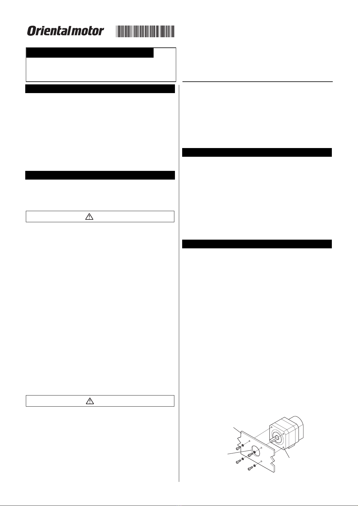
 How to install the motor
Install the motor onto an appropriate flat metal plate having excellent
vibration resistance and heat conductivity. When installing the motor, secure
it with four bolts (not supplied) through the four mounting holes provided.
Leave no gap between the motor and plate.
Installation method A
Pilot holder
(countersunk or
drilled through)
Metal plate
Mounting holes
2
Installation method B
Mounting plate
Pilot holder
(countersunk and
drilled through)
Motor
type Bolt size
Tightening
torque
[N·m (lb-in)]
Effective
depth
[mm (in.)]
Installation
method
PK24M3 P0.5 1 (8.8) 4.5 (0.18) A
PK26M4 2 (17.7) −B
∗ The square box in the motor type will contain a number representing the
motor length.
 Permissible overhung load and permissible thrust load
The overhung load on the motor’s output shaft or gear output shaft must be
kept within the permissible values listed below. The thrust load must not
exceed the motor’s mass.
Permissible overhung load [N (lb.)]
Distance from the top of motor’s output shaft [mm (in.)]
Motor
type 0 (0) 5 (0.2) 10 (0.4) 15 (0.6)
PK2420 (4.5) 25 (5.6) 34 (7.6) 52 (11.7)
PK2654 (12.1) 67 (15) 89 (20) 130 (29)
∗ The square box in the motor type will contain a number representing the
motor length.
 Installing a load
When connecting a load to the motor, align the centers of the motor’s output
shaft and load shaft. Be careful not to damage the output shaft or the bearings
when installing a coupling or pulley to the motor’s output shaft.
Note Do not apply strong impact to the motor’s shaft, since it
can damage the encoder.
Connection
 Wiring diagram
• 8 lead wire type
Black
White
Blue
Brown
Red
Yellow
Orange
Green A
B
A
B
• 6 lead wire type [( ): Pin number]
Wiring diagram
B
A
Red
(3)
White
(2)
Blue
(1)
(4) Black
(5) Yellow
(6) Green
B
A
Pin assignments of PK244PA,
PK246PA
(6)·····(1)
PK244PAand PK246PAare connector type motor. Use the supplied
motor cable. If you are using the connector set or when you are providing
your own connector or cable, connect based on the pin numbers shown. The
conforming connector and the cable are as follows.
Conforming connector and cable
Housing contact
(Molex)
51103-0600
50351-8XXX
Cable AWG28 to 22 (0.08 to 0.3 mm2)
Cable outer diameter
Ø1.15 to 1.8 mm (0.045 to 0.071 in.)
Stripping the cable
2.3 to 2.8 mm (0.091 to 0.11 in.)
Crimping tool (Molex) 57295-5000
Optional motor cables and connector set (sold separately) are available from
Oriental Motor.
Note • Secure the motor connector cable in place so that the
connection won’t be subjected to stress induced by a
bent cable or the cable’s own mass. The cable’s radius
of curvature should be as large as possible.
• When removing the motor cable, pull it out horizontally
toward the output shaft. The motor may be damaged if
force is applied in any other direction. The motor cable
(both supplied and sold separately) employs a
connector with a lock. When removing this type of cable,
release the connector lock first. Forcibly pulling out the
cable without releasing the connector lock may damage
the motor.
Encoder specifications
Note Use the motor within the encoder specifications.
The HEDS-5540, 5600 and 5640 series encoders by Agilent Technologies,
Inc., are used.
 Absolute maximum ratings
Item Symbol Min. Max. Note
Storage temperature [°C (°F)] TS−40
(−40)
100
(212) −
Operating temperature
[°C (°F)] TA−40
(−40)
100
(212) −
Supplied voltage (V) Vcc −0.5 7 −
Output voltage (V) Vo –0.5 Vcc −
Output voltage/ channel (mA) IOUT –1.0 5 −
Vibration (Hz) −5 1000 20 G
Rotation speed (r/min) −−30,000 −
Rotation acceleration
(rad/sec2) −−250,000 −
 Recommended operating ranges
Item Symbol Min. TYP. Max. Note
Temperature
[°C (°F)] TA−40
(−40) −100
(212) −
Supplied
voltage (V) Vcc 4.5 5.0 5.5 Ripple < 100 mVp-p
Load
capacity (pF) CL−−100 2.7 kΩ, pull-up
Response
frequency
(kHz)
f −−100
Rotating speed (r/min)
×N
60
Note • The encoder specifications are designed to guarantee
operation based on a response frequency of 100 kHz.
However, the encoder can be operated at a minimum
response frequency of 100 kHz.
• 2.7 kΩpull-up resistors required for HEDS-5540 and
5640.
3
 Electrical characteristics
The following characteristic values assume operation under the recommended
operating conditions:
• 2-channel type HEDS-5600 series
Item Symbol Min. TYP.∗Max. Note
Supply current
(mA) Icc −17 40 −
Output voltage
“High” (V) VOH 2.4 −−IOH = –40 µA
max.
Output voltage
“Low” (V) VOL −−0.4 IOL = 3.2 mA
Rise time (ns) tr −200 −
Fall time (ns) tf −50 −
CL= 25 pF
RL= 11 kΩ
pull-up
∗ TYP values are based on VCC = 5.0 V and TA= 25 °C (77 °F)
• 3-channel type HEDS-5540, 5640 series
Item Symbol Min. TYP.∗Max. Note
Supply current
(mA) Icc 30 57 85 −
Output voltage
“High” (V) VOH 2.4 −−IOH = –200 µA
max.
Output voltage
“Low” (V) VOL −−0.4 IOL = 3.86 mA
Rise time (ns) tr −180 −
Fall time (ns) tf −40 −
CL= 25 pF
RL= 2.7 kΩ
pull-up
∗ TYP values are based on VCC = 5.0 V and TA= 25 °C (77 °F)
 Encoder characteristics
Unless otherwise specified, the following characteristics assume that the
encoder unit is installed within the allowable ranges of error and operated
under the recommended operating conditions. Each characteristic value
indicates the worst value within one rotation of the code wheel.
• 2-channel type HEDS-5600 series
Item Symbol Min. TYP.∗Max.
Pulse width error (°e) ∆P −7 45
Logic width error (°e) ∆S −5 45
Phase error (°e) ∆Ø−2 20
Position error (arc min.) ∆θ−10 40
Cycle error (°e) ∆C −3 5.5
∗ TYP values are based on VCC = 5.0 V and TA= 25 °C (77 °F)
• 3-channel type HEDS-5540, 5640 series
Item Symbol Min. TYP.∗Max.
Pulse width error (°e) ∆P −5 35
Logic width error (°e) ∆S −5 35
Phase error (°e) ∆Ø−2 15
Position error (arc min.) ∆θ−10 40
Cycle error (°e) ∆C −3 5.5
Index pulse width (°e) Po 55 90 125
CH.I rise after CH.A and CH.B
fall (ns) [TA: −25 to +100 °C
(−13 to +212 °F)]
t110 100 250
CH.I fall after CH.B or CH.A rise
(ns) [TA: −25 to +100 °C (−13 to
+212 °F)]
t270 150 1000
∗ TYP values are based on VCC = 5.0 V and TA= 25 °C (77 °F)
 Output waveform
C
P
Po
CH.
A
CH.I
CH.B
S1 S2
t1 t2
Ø
S3 S4
2.4 V
0.4 V
2.4 V
0.4 V
2.4 V
0.4 V
AMPLITUDE
ROTATION
 Electrical interface
We recommend that the CH.A, CH.B and CH.I outputs be pulled up with a
resistance of 2.7 kΩ(±10%) in order to shorten the rise time of the output
pulse. Install a pull-up resistor near the encoder (within 1 m).
Pull-up of
encoder output
GND
1
2
3
4
5
RRR
+5 V
R = 2.7 kΩ
To output logi
c
(TTL load)
CH.B
CH.A
CH.I
Vcc
 Applicable connectors
Manufacturer Model numbers
Tyco Electronics
AMP
103686-4
640442-5
Du Pont 65039-032 (housing)
4825X-000 (contact)
Avago Technologies
Limited
HEDS-8902 (for 2 channels: 4 lead wires)
HEDS-8903 (for 3 channels: 5 lead wires)
Molex 2695 series (housing)
2759 series (contact)
 Definition of terms
• Count (N)
Number of pulses per rotation of the code wheel.
• One cycle
One output pulse cycle = 360°e (electrical angle)
• Position error (∆θ)
Difference between the shaft’s actual rotating angle and the rotating angle
calculated from the encoder’s output pulse count.
• Cycle error (∆C)
Deviation from the ideal value (360°/ N) of the shaft’s actual rotating angle
relative to the encoder output pulse per period, expressed as an electrical
angle.
• Pulse width (P)
Width of the output pulse in the High state within a cycle, expressed as an
electrical angle.
• Pulse width error (∆P)
Deviation of the pulse width from the ideal value (180°e).
• Logic value (S)
Width corresponding to any of the four Logic states within each cycle formed
by the outputs of phases A and B and expressed as an electrical angle.
• Logic width error (∆S)
Deviation of logic width from the ideal value (90°e).
• Phase (
Ø
)
Phase difference between the outputs of phase A and that of phase B,
measured at the centers of the respective High pulses.
• Phase error (∆
Ø
)
Deviation of phase from the ideal value (90°e).
4
• Rotating direction
When the motor’s shaft rotates clockwise, the output pulse of phase A rises
first. When it rotates in the counterclockwise direction, the output pulse of
phase B rises first. (The motor shaft’s rotating direction indicates the
direction as viewed from the motor shaft side.)
• Index pulse width (Po)
The number of electronical degrees that an index output is high during one
full shaft rotation. This value is nominally 90°e or 1/4 cycle.
Inspection
It is recommended that periodic inspections be conducted for the items listed
below after each operation of the motor. If an abnormal condition is noted,
discontinue any use and contact your nearest office.
• Check for any unusual noises in the motor’s bearings (ball bearings) or
other moving parts.
• Are there any loose connector connections, or any scratches or signs of
stress in the motor cable?
• Are the motor’s output shaft and load shaft out of alignment?
Precautions for use
• Operate the motor with a surface temperature not exceeding 100 °C
(212 °F).
The motor casing’s surface temperature may exceed 100 °C (212 °F) under
certain conditions (ambient temperature, operating speed, duty, etc.).
Keeping the surface temperature of the motor casing below 100 °C (212 °F)
will also maximize the life of the motor bearings (ball bearings).
• Do not apply strong physical impact to the motor’s shaft.
The motor’s shaft is equipped with an optical encoder. To prevent damage to
the encoder, when transporting the motor or connecting a load, please handle
the motor shaft carefully so as to protect it from strong impact.
• Unauthorized reproduction or copying of all or part of this manual is
prohibited.
• Oriental Motor shall not be liable whatsoever for any problems relating
to industrial property rights arising from use of any information, circuit,
equipment or device provided or referenced in this manual.
• Characteristics, specifications and dimensions are subject to change
without notice.
• While we make every effort to offer accurate information in the
manual, we welcome your input. Should you find unclear descriptions,
errors or omissions, please contact the nearest office.
• is a registered trademark or trademark of Oriental
Motor Co., Ltd., in Japan and other countries.
© Copyright ORIENTAL MOTOR CO., LTD. 2008
Printed on Recycled Pape
r
• Please contact your nearest Oriental Motor office for further information.
Headquarters Tokyo, Japan
Tel:(03)3835-0684 Fax:(03)3835-1890
Tel:01 47 86 97 50 Fax:01 47 82 45 16
Tel:(02)8228-0707 Fax:(02)8228-0708
Technical Support Tel:(800)468-3982
8:30
A.M.
to 5:00
P. M .
, P.S.T. (M-F)
7:30
A.M.
to 5:00
P. M .
, C.S.T. (M-F)
E-mail: techsupport@orientalmotor.com
www.orientalmotor.com
Headquarters and Düsseldorf Office Tel:0211-52067-00 Fax:0211-52067-099
Munich Office Tel:089-3181225-00 Fax:089-3181225-25
Hamburg Office Tel:040-76910443 Fax:040-76910445
Tel:01256-347090 Fax:01256-347099
Tel:02-93906346 Fax:02-93906348
Tel:(6745)7344 Fax:(6745)9405
KOREA
Tel:(032)822-2042~3 Fax:(032)819-8745
Tel:(03)22875778 Fax:(03)22875528
Tel:66-2-254-6113 Fax:66-2-254-6114

This manual suits for next models

4

Other Oriental motor Engine manuals

Oriental motor BMU Series User manual

Oriental motor

Oriental motor BMU Series User manual

Oriental motor PK Series User manual

Oriental motor

Oriental motor PK Series User manual

Oriental motor CRK Series User manual

Oriental motor

Oriental motor CRK Series User manual

Oriental motor World K Series User manual

Oriental motor

Oriental motor World K Series User manual

Oriental motor BLE Series User manual

Oriental motor

Oriental motor BLE Series User manual

Oriental motor K Series User manual

Oriental motor

Oriental motor K Series User manual

Oriental motor BH Series User manual

Oriental motor

Oriental motor BH Series User manual

Oriental motor K II Series User manual

Oriental motor

Oriental motor K II Series User manual

Oriental motor TM Series User manual

Oriental motor

Oriental motor TM Series User manual

Oriental motor BLM230 User manual

Oriental motor

Oriental motor BLM230 User manual

Oriental motor World K Series User manual

Oriental motor

Oriental motor World K Series User manual

Oriental motor K Series User manual

Oriental motor

Oriental motor K Series User manual

Oriental motor BLM Series User manual

Oriental motor

Oriental motor BLM Series User manual

Oriental motor CVD512B*-KSC series User manual

Oriental motor

Oriental motor CVD512B*-KSC series User manual

Oriental motor BLM5120HPM User manual

Oriental motor

Oriental motor BLM5120HPM User manual

Oriental motor AR Series User manual

Oriental motor

Oriental motor AR Series User manual

Oriental motor K II Series User manual

Oriental motor

Oriental motor K II Series User manual

Oriental motor BLE2 Series User manual

Oriental motor

Oriental motor BLE2 Series User manual

Oriental motor BLH Series User manual

Oriental motor

Oriental motor BLH Series User manual

Oriental motor World K Series User manual

Oriental motor

Oriental motor World K Series User manual

Oriental motor BLH Series User manual

Oriental motor

Oriental motor BLH Series User manual

Oriental motor CVD Series User manual

Oriental motor

Oriental motor CVD Series User manual

Oriental motor NX Series User manual

Oriental motor

Oriental motor NX Series User manual

Oriental motor AlphaStep AR Series User manual

Oriental motor

Oriental motor AlphaStep AR Series User manual

Popular Engine manuals by other brands

Power Fist 8913196 manual

Power Fist

Power Fist 8913196 manual

Ebmpapst M3G084 Disassembly instructions

Ebmpapst

Ebmpapst M3G084 Disassembly instructions

Vanguard 610000 Operator's manual

Vanguard

Vanguard 610000 Operator's manual

woodmizer D17 Safety, Operation, Maintenance & Parts Manual

woodmizer

woodmizer D17 Safety, Operation, Maintenance & Parts Manual

AOK BASIC AUTO AM45 quick start guide

AOK

AOK BASIC AUTO AM45 quick start guide

Ebmpapst M3G150-IF21-52 operating instructions

Ebmpapst

Ebmpapst M3G150-IF21-52 operating instructions

Turn Key LS3 installation guide

Turn Key

Turn Key LS3 installation guide

Vemco K21B Series Additional Installation, Operating and Maintenance Instructions

Vemco

Vemco K21B Series Additional Installation, Operating and Maintenance Instructions

Vanguard 430447 Installation guidelines

Vanguard

Vanguard 430447 Installation guidelines

HunterDouglas MOTOLUX TURNILS 802343018 Programming instructions

HunterDouglas

HunterDouglas MOTOLUX TURNILS 802343018 Programming instructions

woodmizer LT28 D17 Safety, Operation, Maintenance & Parts Manual

woodmizer

woodmizer LT28 D17 Safety, Operation, Maintenance & Parts Manual

HunterDouglas MOTOLUX TURNILS 802142000 Programming instructions

HunterDouglas

HunterDouglas MOTOLUX TURNILS 802142000 Programming instructions

E-MAG E-113 Installation & operating guide

E-MAG

E-MAG E-113 Installation & operating guide

AOK AM43 manual

AOK

AOK AM43 manual

Wahlberg Roll Down manual

Wahlberg

Wahlberg Roll Down manual

ULPOWER UL350 operating manual

ULPOWER

ULPOWER UL350 operating manual

Wilesco D15 manual

Wilesco

Wilesco D15 manual

Mercury Bravo One Series user manual

Mercury

Mercury Bravo One Series user manual

manuals.online logo
manuals.online logoBrands
  • About & Mission
  • Contact us
  • Privacy Policy
  • Terms and Conditions

Copyright 2025 Manuals.Online. All Rights Reserved.