3. Installation
Installation conditions
Install the motor and capacitor in a location that meets the following conditions. Using the motor and capacitor in a location that does not satisfy
these conditions could damage it.
3.1 Mounting the motor
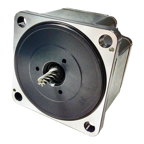
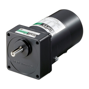
1) Round shaft motors Drill holes in the mounting plate that match the screws and the motor’s dimensions.
Use screws, washers, and nuts listed below to fasten the motor to the mounting
plate. Make sure that no gaps are left between the motor and the surface of the
mounting plate.
Use screws of an appropriate length.
Note:Do not insert the motor into the mounting hole
at an angle or force it in, as this could scratch
the flange and damage the motor.
2) Pinion shaft motor
Drill holes in the mounting plate that match the screws and the motor’s
dimensions.
Attach the motor and gearhead using the screws supplied with the gearhead
(gearhead sold separately).
Fasten the screws supplied with the gearhead to the mounting plate. Attach so
that no gaps are left between the motor flange surface and the gearhead pilot
section end surface.
Refer to the gearhead operation manual for further details concerning mounting
(gearhead sold separately).
Note: Use the gearhead of the same type of pinion shaft as the motor.
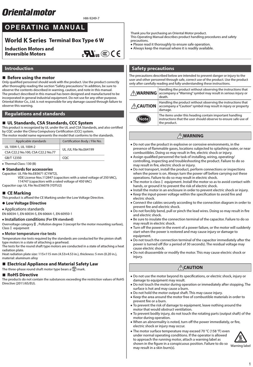
Motors have been designed and inspected according to the following standards, and they are certified/recognized by the certification bodies listed
below and under the China product Compulsory Certification system(CCC system). Recognized name and certified name are motor model name.
Motors (except for the 5IK90GU-SWT and 5IK90A-SWT)are recognized by UL and certified by VDE.
The certificate by VDE is valid only for the motor assembly itself. The capacitor is not included in the certificate.
However, both the motor assembly and capacitor combined have been tested against and have passed EN60950 Annex B.8.
5IK90GU-SWT and 5IK90A-SWT are recognized by UL and certified by DEMKO.
*Voluntary display of the CE mark conforming to the Low Voltage Directives.
・Standards UL1004, UL2111, CSA C22.2 No.100, CSA C22.2 No.77, EN60950, GB12350
・Certification Body UL File No.E64199 (6W type), File No.E64197 (25W 〜90W type)
VDE, DEMKO, CQC
・Applications for standard EN60034-1, EN60034-5, IEC60034-11, IEC60664-1
A Running Heating Test and a Locked-Rotor Test has been conducted with a aluminum radiation plate of size indicated below.
For the motor with a gear head, tests has been conducted with a gear head instead of the radiation plate.
・Installation Conditions Overvoltage category II, Pollution degree 2, Class Iequipment (For EN/IEC standard)
When the machinery to which the motor is mounted requires overvoltage category III and pollution degree 3
pecifications,nstall the motor in a cabinet that comply with IP54 and connect to power supply via an isolation transformer.
・Certification for Accessories Capacitor:UL File No.E83671 (CYWT2)
VDE Licence No.114747 (for only capacitor rated voltage 450VAC types)
Capacitor cap:UL File No.E56078 (YDTU2)
※Dimensions in millimeters(inches).
First number in motor name
2
4
5(40W)
5(60W,90W)
size
115×115(4.53×4.53)
135×135(5.31×5.31)
165×165(6.50×6.50)
200×200(7.87×7.87)
thickness
5
(0.20)
material
aluminium
・Indoors
・Ambient temperature:-10˚C(14˚F)〜+40˚C(104˚F) (avoid freezing)
( -10˚C(14˚F) 〜+50˚C(122˚F) for 100V/200V )
・Ambient humidity: 85% max. (avoid condensation)
・Not exposed to explosive, flammable, or corrosive gas
・Not exposed to direct sunlight
・Not exposed to dust
・Not exposed to water or oil
・A place where heat can escape easily
・Not exposed to continuous vibration or excessive impact
・1,000 meters or less above sea level
・Overvoltage category II, Pollution degree 2, Class Iequipment
(For EN/IEC standard)
When the machinery to which the motor is mounted requires
overvoltage category III and pollution degree 3 specifications,
install the motor in a cabinet that comply with IP54 and connect to
power supply via an isolation transformer.
First letter of motor
model name
2
4
5
Screw size
M4
M5
M6
Tightening torque
2.0N•m (20kgfcm)
2.5N•m (25kgfcm)
3.0N•m (30kgfcm)
3) Motor with cooling fan
When mounting a motor with a cooling fan onto a device, open a ventilation hole or leave 10 millimeters(0.4inches) or more behind the fan
cover so that the cooling inlet on the back of the motor cover is not blocked.
3. 2 Mounting the capacitor (For only single-phase motors)
Before mounting the provided capacitor,check that the capacitor’s capacitance matches that stated on the motor’s
name plate .
Use M4 screws to mount the capacitor (screws not provided).
Note -Do not let the screw fastening torque exceed 1 N・m (10 kgfcm) to prevent damage to the mounting feet.
-Mount capacitor at least 10 cm(3.94inches) away from the motor. If it is located closer, the life of the
capacitor will be shortened.
※Dimensions in millimeters(inches).

