1
OPERATING MANUAL
Thank you for purchasing ORIENTAL MOTOR products.
Please read this operating manual thoroughly before
installing and operating the motor, and always keep
the manual where it is readily accessible.
Induction Motors
HM-9139-5
1. Precautions .......................................... Page 1
2. Checking the package contents........... Page 1
3. Installation............................................ Page 3
4. Connection and Operation................... Page 5
5. Time Rating .................................................. Page 7
6. Locked rotor burnout protection ................... Page 7
7. Troubleshooting............................................ Page 7
<Table of contents>
BH Series
1. Precautions
1. 1 Precautions for Installation
• Do not use in a place where there is flammable gas and/or corrosive gas.
• When installing the motor into your equipment, ensure that the motor lead wires are fixed and do not move.
In addition, do not apply any pressure to these lead wires.
• Motors for use only in equipment of protection class I.
Motore zur Verwendung in Geräten der Schutzklasse I.
• The motor housing must be mounted with a screw and spring washer to the ground point of the equipment.
Die Gehäuse der Motore sind mit einer Schraube und Zahnscheibe sicher mit dem geerdeten Gehäuse des Gerätes zu verbinden.
• Installation must be performed by a qualified installer.
1. 2 Precautions for Operation
• The motor case temperature can exceed 70°C (depending on operation conditions). In case motor is
accessible during operation, please attach the following warning label so that it is clearly visible.
• Always turn off the power to the motor before conducting checks or performing work on the motor.
Thermally protected motors will restart automatically when motor temperature falls below a certain level.
2. 1 Checking the contents
2. Checking the package contents
Make sure that you have received all of the items listed below. If an accessory is missing or damaged, contact the nearest ORIENTAL MOTOR office.
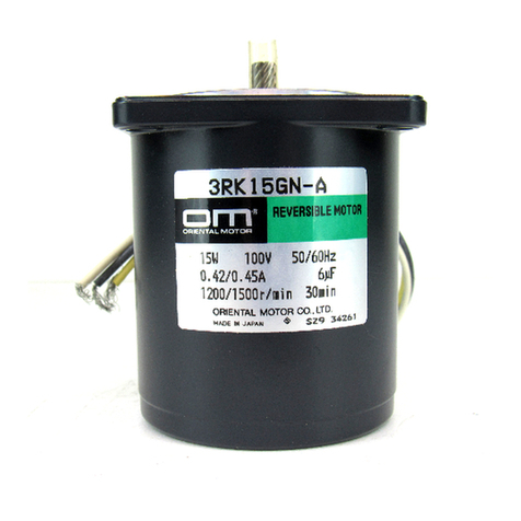
-Motor....................................... 1
-Capacitor ................................ 1 (for only single-phase motors)
-Capacitor cap ......................... 1 (for only single-phase motors)
-Key.......................................... 1 (for only combination types)
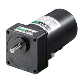
For BH6G2-
, BH8G-
and BH6G2-
RA, a key is fixed on the gearhead’s shaft.
-Set of mounting bolts ............. 1 (for only combination types BH6G2-
, BH8G-
)
Mounting screws ............... 4
Nuts ................................... 4
Washers ............................ 4
Spring washers.................. 4
-This operating manual............ 1
Warning label
Copyright ORIENTAL MOTOR CO., LTD. 2006
