manuals.online logo
Brands
  1. Home
  2. •
  3. Brands
  4. •
  5. Oriental motor
  6. •
  7. Engine
  8. •
  9. Oriental motor World K Series User manual

Oriental motor World K Series User manual

Thank you for purchasing an Oriental Motor product.
This Operating Manual describes product handling procedures and safety precautions.
•Please read it thoroughly to ensure safe operation.
•Always keep the manual where it is readily available.
•Only qualied personnel of electrical and mechanical engineering should work with the product.
•Use the product correctly after thoroughly reading the section “Safety precautions.”
In addition, be sure to observe the contents described in warning and caution in this document.
•The product described in this document is designed and manufactured to be incorporated in general
industrial equipment. Do not use for any other purpose.
Oriental Motor Co., Ltd. is not responsible for any compensation for damage caused through failure to
observe this warning.
World KSeries
Induction Motors
Reversible Motors
Electromagnetic Brake Motors
OPERATING MANUAL
HM-9447
1. Safety precautions....................... 3
2. Checking the product ................. 4
2.1 Package contents ...............................4
2.2 Information about nameplate.......4
2.3 How to identify the product
model......................................................4
3. Installation .................................... 5
3.1 Installation location...........................5
3.2 Installing the motor...........................5
4. Connection.................................... 8
4.1 Lead wire type .....................................8
4.1.1 Induction motors
Single-phase type........................8
4.1.2 Induction motors
Single-phase
2-Pole high-speed type .............9
4.1.3 Induction motors
Three-phase type...................... 10
4.1.4 Reversible motors
Single-phase type..................... 11
4.2 Terminal box type............................ 12
4.2.1 Induction motors
Single-phase type..................... 12
4.2.2 Induction motors
Three-phase type...................... 13
4.2.3 Reversible motors
Single-phase type..................... 14
4.2.4 Connecting to the terminal
box ................................................. 15
4.3 Electromagnetic brake motors... 17
4.3.1 Single-phase type..................... 17
4.3.2 Three-phase type...................... 20
4.4 Connecting/installing the
capacitor
(Single-phase type only)............... 21
4.5 Connecting the Protective Earth
Terminal .............................................. 21
5. Operation ....................................22
5.1 Time rating......................................... 22
5.2 Rotation direction of the
gearhead output shaft................... 22
6. Burning protection for locked
condition .....................................23
6.1 Thermal protection......................... 23
6.2 Impedance protection................... 23
7. Gearheads ...................................24
7.1 Checking the product.................... 24
7.2 Precautions for use ......................... 25
7.3 Parallel shaft gearheads................ 26
7.4 Hollow shaft gearheads ................ 29
7.5 Solid shaft gearheads .................... 33
8. Maintenance and inspection...36
8.1 Inspection .......................................... 36
8.2 Warranty ............................................. 36
8.3 Disposal............................................... 36
9. Troubleshooting ........................37
10. Specications .............................38
10.1 Specications.................................... 38
10.2 General specications.................... 38
11. Regulations and standards ......39
Table of contents
Gearhead
Motor
Capacitor
Troubleshooting
Refer to this chapter if the motor does not rotate or if the motor rotates in the opposite direction.
The model name and the connection diagram are shown
on the same page.
Searching PDF by the model name can check the connection
diagram corresponding to it.
Connection
Installation Refer to this chapter when assembling a motor and
a gearhead.
AC power
supply
P.5 -
P.37 -
P.8 -
Click Table of contents on the
upper right of each page to return to the
"Table of contents."
Table of contents
3
1. Safety precautions
When the overheat protection device (thermal protector) of the electromagnetic brake motor is
activated, the electromagnetic brake does not hold the motor shaft (a load). Provide safety measures
separately. This may result in injury or damage to equipment.
The motor is Class
Ⅰ
equipment. Install the motor so that it is out of the direct reach of users, or ground
if users can touch it. Failure to do so may result in electric shock.
Always keep the power supply voltage within the specied range. Failure to do so may result in re or
electric shock.
Perform connections securely according to the connection diagram. Failure to do so may result in re
or electric shock.
Insulate the connection terminals of the included capacitor. Failure to do so may result in electric
shock.
Turn o the power in the event of a power failure. Otherwise, the motor may suddenly start when the
power is restored, causing injury or damage to equipment.
Do not use the motor beyond the specications. Doing so may result in re, electric shock, injury, or
damage to equipment.
Do not lift up the motor by holding the output shaft, the lead wire, or the cable. Doing so may result
in injury.
Do not touch the motor output shaft (shaft end or pinion section) with bare hands. Doing so may
result in injury.
Keep the area around the motor free of combustible materials. Failure to do so may result in re or a
skin burn(s).
Do not leave anything around the motor that would obstruct ventilation. Doing so may result in
damage to equipment.
Do not touch the motor while operating or immediately after stopping. The surface of the motor is
hot and it may cause a skin burn(s).
Do not touch the rotating part (output shaft, cooling fan) while operating the motor. Doing so may
result in injury.
Provide a cover over the rotating part (output shaft). Failure to do so may result in injury.
When an abnormality is generated, turn o the power immediately. Failure to do so may result in re,
electric shock, or injury.
The motor surface temperature may exceed 70 °C (158 °F) even under normal
operating conditions. If the operator is allowed to approach the operating motor,
attach a warning label on a conspicuous position as shown in the gure. Failure to
do so may result in a skin burn(s). Warning label
The precautions described below are intended to ensure the safe and correct use of the product, and to prevent
the user and other personnel from exposure to the risk of injury.
Use the product only after carefully reading and fully understanding these instructions.
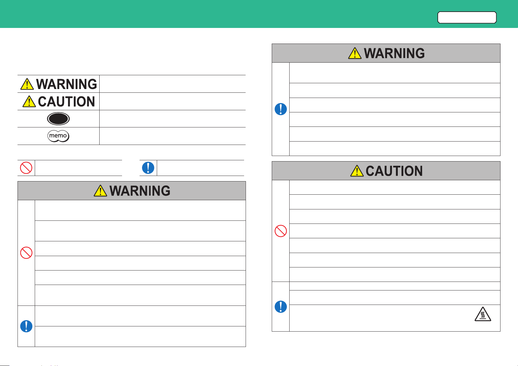
Description of signs
Handling the product without observing the instructions that accompany
a“WARNING”symbol may result in serious injury or death.
Handling the product without observing the instructions that accompany
a“CAUTION”symbol may result in injury or property damage.
Note The items under this heading contain important handling instructions
that the user should observe to ensure safe use of the product.
The items under this heading contain related information and
contents to gain a further understanding of the text in this manual.
Explanation of graphic symbols
Indicates “prohibited”actions that must
not be performed.
Indicates “compulsory”actions that must
be performed.
Do not use the product in explosive or corrosive environments, in the presence of ammable gases, in
places subjected to splashing water, or near combustibles. Doing so may result in re, electric shock,
or injury.
Do not transport, install, connect, or inspect the product while the power is supplied. Always turn
o the power before carrying out these operations. This may result in electric shock or damage to
equipment.
Do not use the electromagnetic brake of the electromagnetic brake motor as a safety brake. Provide
safety measures separately. This may result in injury or damage to equipment.
Do not forcibly bend, pull, or pinch the lead wire and the cable. Doing so may result in re, electric
shock, or damage to equipment.
Do not touch the connection terminal of the capacitor immediately after turning o the power supply
(for a period of 30 seconds). Residual voltage may cause electric shock.
Do not disassemble or modify the motor. Doing so may result in electric shock, injury, or damage to
equipment. Refer all such internal inspections and repairs to the branch or sales oce from which you
purchased the product.
Only qualied and educated personnel should be allowed to perform installation, connection,
operation and inspection/troubleshooting of the product. Handling by unqualied and uneducated
personnel may result in re, electric shock, injury, or damage to equipment.
Turn o the power supply if the overheat protection device (thermal protector) of the motor
is activated. The motor may suddenly start rotating when the overheat protection device is
automatically returned, causing injury or damage to equipment.
Table of contents
4
2.1 Package contents
Verify that the items listed below are included.
Report any missing or damaged items to the branch or sales oce from which you purchased the product.
Motor.............................................................................. 1 unit
Capacitor (Single-phase motor only) ................. 1 piece
Capacitor cap (Single-phase motor only) ......... 1 piece
Instructions and Precautions for Safe Use ........ 1 copy
2.2 Information about nameplate
Tell us the model name, product serial number, and manufacturing date when you contact us.
MODEL
INDUCTION MOTOR
ORIENTAL MOTOR CO.,LTD.
TOKYO 110-8536 JAPAN MADE IN JAPAN
产 品 名 称:电容运转异步电动机
制造商名称:东方马达株式会社 制 造 地:日 本
过 热 保 护:热保护的
Motor model
Motor specications
Manufacturing date
Serial number
The position describing the information may vary depending on the product.
2.3 How to identify the product model
Verify the model name of the purchased product against the model shown on the package label.
The model name describe on the motor nameplate does not have a code such as J, U, or Erepresenting a
capacitor type at the end of the model name.
5 R K 40 GN - AW 2 M J
1 2 3 4 5 6 7 8 9
1 Motor frame size 0: 42 mm (1.65 in.) 2: 60 mm (2.36 in.) 3: 70 mm (2.76 in.)
4: 80 mm (3.15 in.) 5: 90 mm (3.54 in.)
2 Motor type I: Induction motor
R: Reversible motor
3 Output power 1: 1 W 3: 3 W 6: 6 W 15: 15 W 25: 25 W
40: 40 W 60: 60 W 90: 90 W 150: 150 W
4 Motor shaft type, type of pinion
A: Round shaft type
GN: GN type pinion shaft
GE: GE type pinion shaft
5 Power supply voltage / Number of poles
AW: Single-phase 100 VAC, 110/115 VAC 4-pole
BW: Single-phase 100 VAC, 110/115 VAC 2-pole
CW: Single-phase 200 VAC, 220/230 VAC 4-pole
DW: Single-phase 200 VAC, 220/230 VAC 2-pole
SW: Three-phase 200/220/230 VAC 4-pole
TW: Three-phase 200/220/230 VAC 2-pole
UW: Three-phase 380/400/415 VAC 4-pole
6 Identication code 2, 3
7M: Electromagnetic brake motor
8T, T2: Terminal box type Blank: Lead wire type
9 Included capacitor type
J: Capacitor for single-phase 100 VAC, 200 VAC
U: Capacitor for single-phase 110/115 VAC
E: Capacitor for single-phase 220/230 VAC
Blank: Three-phase motor
2. Checking the product
Table of contents
5
3.1 Installation location
Install the product in a well-ventilated location that provides easy access for inspection.
•Inside an enclosure that is installed indoors (provide vent holes)
•Operating ambient temperature*
1 W, 3 W motors:
-
10 to +40 °C (+14 to +104 °F) (non-freezing)
6 W to 90 W motors
Single-phase 100 VAC, Single-phase 200 VAC, Three phase 200 VAC:
-
10 to +50 °C (+14 to +122 °F) (non-freezing)
Other voltages:
-
10 to +40 °C (+14 to +104 °F) (non-freezing)
* When a right-angle gearhead is assembled, the lower temperature limit is 0 °C (+32 °F).
•Operating ambient humidity: 85% or less (non-condensing)
•Area free of explosive atmosphere, toxic gas (such as sulfuric gas), or liquid
•Area not exposed to direct sun
•Area free of excessive amount of dust, iron particles or the like
•Area not subject to splashing water (rain, water droplets), oil (oil droplets) or other liquids
•Area free of excessive salt
•Area not subject to continuous vibration or excessive shocks
•Area free of excessive electromagnetic noise (from welders, power machinery, etc.)
•Area free of radioactive materials, magnetic elds, or vacuum
•Altitude: Up to 1000 m (3300 ft.) above sea level
3.2 Installing the motor
Round shaft type
Make a hole in the mounting plate and use screws to secure the motor. (Screws for mounting the motor are not
included.)
Install so that there is no gap between the product and the mounting plate.
Model Screw size Tightening torque
Motor
Mounting plate
0IK, 0RK M3 1.0 Nm (8.8 lb-in)
2IK, 2RK M4 2.0 Nm (17.7 lb-in)
3IK, 3RK M5 2.5 Nm (22 lb-in)
4IK, 4RK
5IK, 5RK M6 3.0 Nm (26 lb-in)
Note Do not install the motor to the mounting hole diagonally or assemble the motor forcibly.
Doing so may damage the ange pilot section, thereby resulting in damage to the motor.
zMounting hole dimensions [Unit: mm (in.)]
Model ØA B ØCH7 ØD
B
B
ØA
ØCH7
4ר
D
0IK, 0RK 48 (1.89) 33.94 (1.336) 37.6
+0.025
0
(1.4803
+0.0010
0
) 3.5 (0.138)
2IK, 2RK 70 (2.76) 49.50 (1.949) 54
+0.030
0
(2.1260
+0.0012
0
) 4.5 (0.177)
3IK, 3RK 82 (3.23) 57.98 (2.283) 64
+0.030
0
(2.5197
+0.0012
0
) 5.5 (0.217)
4IK, 4RK 94 (3.70) 66.47 (2.617) 73
+0.030
0
(2.8740
+0.0012
0
) 5.5 (0.217)
5IK, 5RK 104 (4.09) 73.54 (2.895) 83
+0.035
0
(3.2677
+0.0014
0
) 6.5 (0.256)
ØC indicates the diameter of the ange pilot.
zPermissible radial load and permissible axial load
The radial load and the axial load have a great inuence on the
life of the bearings and the strength of the shaft. Make sure not to
exceed the permissible radial load and the permissible axial load.
10 mm (0.39 in.)
20 mm (0.79 in.)
Distance from output shaft end
Axial load
Radial load
Model
Permissible radial load [N (lb.)] Permissible axial load [N (lb.)]
Distance from motor output shaft end Induction motor
Reversible motor
Electromagnetic
brake motor
10 mm (0.39 in.) 20 mm (0.79 in.)
0IK, 0RK 40 (9.0) − 3 (0.67) −
2IK, 2RK 50 (11.2) 110 (24) 10 (2.2) 10 (2.2)
3IK, 3RK 40 (9.0) 60 (13.5)
4IK, 4RK 90 (20) 140 (31) 15 (3.3) 15 (3.3)
5IK40, 5RK40 140 (31) 200 (45)
20 (4.5)
5IK60, 5RK60
240 (54) 270 (60)
16 (3.6)
5IK90, 5RK90,
5IK150 19 (4.2)
Note Failure due to fatigue may occur when the bearings and output shaft are subject to repeated
loading by a radial or axial load that is in excess of the permissible limit.
3. Installation
3. Installation
6
Table of contents
Pinion shaft type
zAssembling the motor and gearhead
Check the model names for the motor and gearhead.
Only a motor and a gearhead having the same frame size and the same type of pinion can be combined.
[Example]
4 IK25 GN -AW2 4 GN 25K
• Motor model • Gearhead model
Frame size
Pinion type
Assemble the gearhead to the motor in a condition where the motor output shaft is set upward. Wipe o the
grease if it is adhered to the pilot section of the gearhead.
Keep the pilot sections of the motor and gearhead in parallel, and assemble while slowly rotating the gearhead
clockwise/counterclockwise. Also, assemble so that no gap remains between the motor and gearhead.
When using a decimal gearhead, install it between the motor and the gearhead.
Motor output shaft
Pilot section
Assemble while slowly rotating
clockwise/counterclockwise.
Note Do not remove the white grease-seal tube of the 1 W and 3 W
motors. If the white grease-seal tube is removed, grease in the
gearhead may penetrate into the inside of the motor, resulting in
damage to the motor.
Do not remove
the white
grease-seal tube.
Refer to the following pages for assembling the hollow shaft gearhead and the solid shaft gearhead.
•Hollow shaft gearhead p.29
•Solid shaft gearhead p.33
Do not forcibly assemble a motor and a gearhead, or do not
hit the motor output shaft with the gearhead or the gear.
Also, prevent metal objects or foreign substances from
entering in the gearhead.
The motor output shaft or the gear may be damaged, resulting
in noise or shorter service life.
Motor
Gearhead
Motor
output shaf
t
Gear
Precaution when assembling
3. Installation
7
Table of contents
zInstalling to equipment
Use the mounting screw set included with a gearhead to secure the motor and gearhead to the mounting plate.
Install so that there is no gap between the product and the mounting plate.
Use screws included with a decimal gearhead when using it.
Motor
Gearhead
Screws
Mounting plate
Nuts
Plain washers
Make the mounting hole which dimensions are
at least 1 mm (0.04 in.) larger than the mounting
boss of output shaft.
Mounting boss of output shaft
If the motor and gearhead are about to come o when installing to
equipment, temporarily x the motor and gearhead with tape.
Mounting plate
Tape
Refer to the page of each gearhead for mounting hole dimensions, mounting screw dimensions, and installation
of a load.
•Parallel shaft gearhead p.26
•Hollow shaft gearhead p.30
•Solid shaft gearhead p.34
Motor equipped with cooling fan
When installing a motor with cooling fan onto equipment, leave a
space of 10 mm (0.39 in.) or more behind the fan cover or open a
ventilation hole so that the intake on the rear part of the motor is
not blocked.
Intake
Equipment
Outlet
10 mm (0.39 in.) or more
How to change the direction of the cable outlet position
(Electromagnetic brake motor only)
In the case of 60 W and 90 W motors, the cable outlet position is set toward the direction of the motor output
shaft at the time of shipment.
The direction of the cable outlet position can be changed by 180 degrees. Change the direction according to
the following steps.
1. Remove the screws of the cable clamp, and remove
the upper unit of the cable clamp. M3
Hexagonal socket head screw
s
Cable clamp
Cable
2. Change the direction of the cable by 180 degrees, and
turn the cable clamp by 180 degrees.
3. Install the upper unit of the cable clamp and x it with
screws.
Tightening torque of screw: 0.5 to 0.7 N·m (4.4 to 6.1 lb-in)
Table of contents
8
4.1 Lead wire type
4.1.1 Induction motors Single-phase type
zModel
Output
power Model Motor model Capacitor model
1 W
0IK1GN-AW2J 0IK1GN-AW2 CH15FAUL
0IK1A-AW2J 0IK1A-AW2
0IK1GN-AW3U 0IK1GN-AW3 CH10FAUL
0IK1A-AW3U 0IK1A-AW3
0IK1GN-CW2J 0IK1GN-CW2 CH035BFAUL
0IK1A-CW2J 0IK1A-CW2
3 W
0IK3GN-BW2J 0IK3GN-BW2 CH18FAUL
0IK3A-BW2J 0IK3A-BW2
0IK3GN-BW3U 0IK3GN-BW3 CH15FAUL
0IK3A-BW3U 0IK3A-BW3
0IK3GN-DW2J 0IK3GN-DW2 CH045BFAUL
0IK3A-DW2J 0IK3A-DW2
6 W
2IK6GN-AW2J 2IK6GN-AW2 CH35FAUL2
2IK6A-AW2J 2IK6A-AW2
2IK6GN-AW2U 2IK6GN-AW2 CH25FAUL2
2IK6A-AW2U 2IK6A-AW2
Output
power Model Motor model Capacitor model
6 W
2IK6GN-CW2J 2IK6GN-CW2 CH08BFAUL
2IK6A-CW2J 2IK6A-CW2
2IK6GN-CW2E 2IK6GN-CW2 CH06BFAUL
2IK6A-CW2E 2IK6A-CW2
15 W
3IK15GN-AW2J 3IK15GN-AW2 CH55FAUL2
3IK15A-AW2J 3IK15A-AW2
3IK15GN-AW2U 3IK15GN-AW2 CH45FAUL2
3IK15A-AW2U 3IK15A-AW2
3IK15GN-CW2J 3IK15GN-CW2 CH15BFAUL
3IK15A-CW2J 3IK15A-CW2
3IK15GN-CW2E 3IK15GN-CW2 CH10BFAUL
3IK15A-CW2E 3IK15A-CW2
25 W
4IK25GN-AW2J 4IK25GN-AW2 CH80CFAUL2
4IK25A-AW2J 4IK25A-AW2
4IK25GN-AW2U 4IK25GN-AW2 CH65CFAUL2
4IK25A-AW2U 4IK25A-AW2
4IK25GN-CW2J 4IK25GN-CW2 CH20BFAUL
4IK25A-CW2J 4IK25A-CW2
4IK25GN-CW2E 4IK25GN-CW2 CH15BFAUL
4IK25A-CW2E 4IK25A-CW2
40 W 5IK40GN-AW2J 5IK40GN-AW2 CH110CFAUL2
5IK40A-AW2J 5IK40A-AW2
Output
power Model Motor model Capacitor model
40 W
5IK40GN-AW2U 5IK40GN-AW2 CH90CFAUL2
5IK40A-AW2U 5IK40A-AW2
5IK40GN-CW2J 5IK40GN-CW2 CH30BFAUL
5IK40A-CW2J 5IK40A-CW2
5IK40GN-CW2E 5IK40GN-CW2 CH23BFAUL
5IK40A-CW2E 5IK40A-CW2
60 W
5IK60GE-AW2J 5IK60GE-AW2 CH200CFAUL2
5IK60A-AW2J 5IK60A-AW2
5IK60GE-AW2U 5IK60GE-AW2 CH180CFAUL2
5IK60A-AW2U 5IK60A-AW2
5IK60GE-CW2J 5IK60GE-CW2 CH50BFAUL
5IK60A-CW2J 5IK60A-CW2
5IK60GE-CW2E 5IK60GE-CW2 CH40BFAUL
5IK60A-CW2E 5IK60A-CW2
90 W
5IK90GE-AW2J 5IK90GE-AW2 CH280CFAUL2
5IK90A-AW2J 5IK90A-AW2
5IK90GE-AW2U 5IK90GE-AW2 CH200CFAUL2
5IK90A-AW2U 5IK90A-AW2
5IK90GE-CW2J 5IK90GE-CW2 CH70BFAUL
5IK90A-CW2J 5IK90A-CW2
5IK90GE-CW2E 5IK90GE-CW2 CH60BFAUL
5IK90A-CW2E 5IK90A-CW2
zConnection diagram
Insulate all the wire connections, such as the connection between the motor and
the power supply and that between the motor and the capacitor.
Use the Protective Earth Terminal to ground the motor.
Use lead wires for power supply equal to or thicker than the lead wire size shown
below.
Motors of 1 W and 3 W: AWG 24 (0.2 mm2) or thicker
Motors of 6 W or larger: AWG 20 (0.5 mm2) or thicker
•Connecting/installing the capacitor p.21
•Connecting the Protective Earth Terminal p.21
Operation p.22
Clockwise: CW
N
Red
Black
L
White
Po
wer supply
Groundin
g
CW
Counterclockwise: CCW
CCW
N
Red
Black
White
Groundin
g
L
Po
wer supply
•The rotation direction varies depending on the gear ratio of the gearhead. p.22
4. Connection
4. Connection
9
Table of contents
4.1.2 Induction motors
Single-phase
2-Pole high-speed type
zModel
Output
power Model Motor model Capacitor model
40 W
4IK40A-BW2J
4IK40A-BW2
CH90CFAUL2
4IK40A-BW2U CH75CFAUL2
4IK40A-DW2J 4IK40A-DW2 CH23BFAUL
4IK40A-DW3E 4IK40A-DW3 CH18BFAUL
Output
power Model Motor model Capacitor model
60 W
4IK60A-BW2J 4IK60A-BW2 CH140CFAUL2
4IK60A-BW2U CH100CFAUL2
4IK60A-DW2J 4IK60A-DW2 CH30BFAUL
4IK60A-DW3E 4IK60A-DW3 CH25BFAUL
5IK60A-BW2J 5IK60A-BW2 CH160CFAUL2
5IK60A-BW2U CH140CFAUL2
5IK60A-DW2J 5IK60A-DW2 CH40BFAUL
5IK60A-DW3E 5IK60A-DW3 CH30BFAUL
Output
power Model Motor model Capacitor model
90 W
5IK90A-BW2J 5IK90A-BW2 CH280CFAUL2
5IK90A-BW2U CH250CFAUL2
5IK90A-DW2J 5IK90A-DW2 CH70BFAUL
5IK90A-DW3E 5IK90A-DW3 CH60BFAUL
150 W
5IK150A-BW2J 5IK150A-BW2 CH400CFAUL2
5IK150A-BW2U CH300CFAUL2
5IK150A-DW2J 5IK150A-DW2 CH100BFAUL
5IK150A-DW3E 5IK150A-DW3 CH80BFAUL
zConnection diagram
Insulate all the wire connections, such as the connection between the motor and the power supply and that between the motor and the capacitor.
Use the Protective Earth Terminal to ground the motor.
Use lead wires for power supply equal to or thicker than the lead wire size of AWG 20 (0.5 mm2).
Clockwise: CW
Black
N
Red
L
White
Gray
Blue
Po
wer supply
Grounding
CW
Counterclockwise: CCW
CCW
Po
wer supply
N
Black
L
White
Blue Grounding
Red
Gray
•Connecting/installing the capacitor p.21
•Connecting the Protective Earth Terminal p.21
Operation p.22
4. Connection
10
Table of contents
4.1.3 Induction motors Three-phase type
zThree-phase 200/220/230 VAC type model
zThree-phase 2-pole high-speed type model
zThree-phase 380/400/415 VAC type model
Output power Model (Motor model) Output power Model (Motor model) Output power Model (Motor model)
6 W 2IK6GN-SW2 2IK6A-SW2 60 W 5IK60A-TW2 25 W 4IK25GN-UW2 4IK25A-UW2
15 W 3IK15GN-SW2 3IK15A-SW2 90 W 5IK90A-TW2 40 W 5IK40GN-UW2 5IK40A-UW2
25 W 4IK25GN-SW2 4IK25A-SW2 150 W 5IK150A-TW2 60 W 5IK60GE-UW2 5IK60A-UW2
40 W 5IK40GN-SW2 5IK40A-SW2 90 W 5IK90GE-UW2 5IK90A-UW2
60 W 5IK60GE-SW2 5IK60A-SW2
90 W 5IK90GE-SW2 5IK90A-SW2
zConnection diagram
Insulate all the wire connections, such as the connection between the motor and the power supply.
Use the Protective Earth Terminal to ground the motor.
The motor rotates in the clockwise direction (CW) if connected as the connection diagram below.
Changing the connection for any two wires of R, S, or T will rotate in the counterclockwise (CCW).
Use lead wires for power supply equal to or thicker than the lead wire size of AWG 20 (0.5 mm2).
Clockwise: CW
L1 (R
)
L2 (S)
L3
(T)
R0C0
R0C0
R0C0
White
Black
Red
Groundin
g
Power supply
CW
•The rotation direction varies depending on the gear ratio of the gearhead. p.22
Protection of contact (Switch)
If the switch is used for starting/stopping the motor or switching the rotation direction, connect the
CR circuit for surge suppression in order to protect the contacts.
R0C0R0 = 5 to 200 
C0 = 0.1 to 0.2 µF 250 VAC*
* For three-phase 380/400/415 VAC
C0 = 0.1 to 0.2 µF 450 VAC
•Connecting the Protective Earth Terminal p.21
Operation p.22
4. Connection
11
Table of contents
4.1.4 Reversible motors Single-phase type
zModel
Output
power Model Motor model Capacitor model
1 W
0RK1GN-AW2J 0RK1GN-AW2 CH18FAUL
0RK1A-AW2J 0RK1A-AW2
0RK1GN-AW3U 0RK1GN-AW3 CH12FAUL
0RK1A-AW3U 0RK1A-AW3
0RK1GN-CW2J 0RK1GN-CW2 CH045BFAUL
0RK1A-CW2J 0RK1A-CW2
6 W
2RK6GN-AW2J 2RK6GN-AW2 CH45FAUL2
2RK6A-AW2J 2RK6A-AW2
2RK6GN-AW2U 2RK6GN-AW2 CH35FAUL2
2RK6A-AW2U 2RK6A-AW2
2RK6GN-CW2J 2RK6GN-CW2 CH10BFAUL
2RK6A-CW2J 2RK6A-CW2
2RK6GN-CW2E 2RK6GN-CW2 CH08BFAUL
2RK6A-CW2E 2RK6A-CW2
Output
power Model Motor model Capacitor model
15 W
3RK15GN-AW2J 3RK15GN-AW2 CH75CFAUL2
3RK15A-AW2J 3RK15A-AW2
3RK15GN-AW2U 3RK15GN-AW2 CH60CFAUL2
3RK15A-AW2U 3RK15A-AW2
3RK15GN-CW2J 3RK15GN-CW2 CH18BFAUL
3RK15A-CW2J 3RK15A-CW2
3RK15GN-CW2E 3RK15GN-CW2 CH15BFAUL
3RK15A-CW2E 3RK15A-CW2
25 W
4RK25GN-AW2J 4RK25GN-AW2 CH100CFAUL2
4RK25A-AW2J 4RK25A-AW2
4RK25GN-AW2U 4RK25GN-AW2 CH80CFAUL2
4RK25A-AW2U 4RK25A-AW2
4RK25GN-CW2J 4RK25GN-CW2 CH30BFAUL
4RK25A-CW2J 4RK25A-CW2
4RK25GN-CW2E 4RK25GN-CW2 CH25BFAUL
4RK25A-CW2E 4RK25A-CW2
40 W
5RK40GN-AW2J 5RK40GN-AW2 CH160CFAUL2
5RK40A-AW2J 5RK40A-AW2
5RK40GN-AW2U 5RK40GN-AW2 CH120CFAUL2
5RK40A-AW2U 5RK40A-AW2
Output
power Model Motor model Capacitor model
40 W
5RK40GN-CW2J 5RK40GN-CW2 CH40BFAUL
5RK40A-CW2J 5RK40A-CW2
5RK40GN-CW2E 5RK40GN-CW2 CH35BFAUL
5RK40A-CW2E 5RK40A-CW2
60 W
5RK60GE-AW2J 5RK60GE-AW2 CH250CFAUL2
5RK60A-AW2J 5RK60A-AW2
5RK60GE-AW2U 5RK60GE-AW2 CH200CFAUL2
5RK60A-AW2U 5RK60A-AW2
5RK60GE-CW2J 5RK60GE-CW2 CH60BFAUL
5RK60A-CW2J 5RK60A-CW2
5RK60GE-CW2E 5RK60GE-CW2 CH50BFAUL
5RK60A-CW2E 5RK60A-CW2
90 W
5RK90GE-AW2J 5RK90GE-AW2 CH350CFAUL2
5RK90A-AW2J 5RK90A-AW2
5RK90GE-AW2U 5RK90GE-AW2 CH300CFAUL2
5RK90A-AW2U 5RK90A-AW2
5RK90GE-CW2J 5RK90GE-CW2 CH80BFAUL
5RK90A-CW2J 5RK90A-CW2
5RK90GE-CW3E 5RK90GE-CW3 CH70BFAUL
5RK90A-CW3E 5RK90A-CW3
zConnection diagram
Insulate all the wire connections, such as the connection between the motor and
the power supply and that between the motor and the capacitor.
Use the Protective Earth Terminal to ground the motor.
The motor rotates in the clockwise direction if the switch (SW) is connected to the
CW side, and it rotates in the counterclockwise direction if connected to the CCW
side.
Use lead wires for power supply equal to or thicker than the lead wire size shown
below.
Motors of 1 W: AWG 24 (0.2 mm2) or thicker
Motors of 6 W or larger: AWG 20 (0.5 mm2) or thicker
Clockwise: CW
Po
wer
supply
L
N
White
Red
Black
Groundin
g
SW CCW
CW
R0C0
R0C0
CW
•The rotation direction varies depending on the gear ratio of the gearhead. p.22
Protection of contact (Switch)
If the switch is used for starting/stopping the motor or
switching the rotation direction, connect the CR circuit for
surge suppression in order to protect the contacts.
R0C0R0 = 5 to 200 
C0 = 0.1 to 0.2 µF 250 VAC
•Connecting/installing the capacitor p.21
•Connecting the Protective Earth Terminal p.21
Operation p.22
4. Connection
12
Table of contents
4.2 Terminal box type
4.2.1 Induction motors Single-phase type
zModel
Output
power Model Motor model Capacitor model
25 W
4IK25GN-AW2TJ 4IK25GN-AW2T CH80CFAUL2
4IK25A-AW2TJ 4IK25A-AW2T
4IK25GN-AW2TU 4IK25GN-AW2T CH65CFAUL2
4IK25A-AW2TU 4IK25A-AW2T
4IK25GN-CW2TJ 4IK25GN-CW2T CH20BFAUL
4IK25A-CW2TJ 4IK25A-CW2T
4IK25GN-CW2TE 4IK25GN-CW2T CH15BFAUL
4IK25A-CW2TE 4IK25A-CW2T
Output
power Model Motor model Capacitor model
40 W
5IK40GN-AW2TJ 5IK40GN-AW2T CH110CFAUL2
5IK40A-AW2TJ 5IK40A-AW2T
5IK40GN-AW2TU 5IK40GN-AW2T CH90CFAUL2
5IK40A-AW2TU 5IK40A-AW2T
5IK40GN-CW2TJ 5IK40GN-CW2T CH30BFAUL
5IK40A-CW2TJ 5IK40A-CW2T
5IK40GN-CW2TE 5IK40GN-CW2T CH23BFAUL
5IK40A-CW2TE 5IK40A-CW2T
60 W
5IK60GE-AW2TJ 5IK60GE-AW2T CH200CFAUL2
5IK60A-AW2TJ 5IK60A-AW2T
5IK60GE-AW2TU 5IK60GE-AW2T CH180CFAUL2
5IK60A-AW2TU 5IK60A-AW2T
Output
power Model Motor model Capacitor model
60 W
5IK60GE-CW2TJ 5IK60GE-CW2T CH50BFAUL
5IK60A-CW2TJ 5IK60A-CW2T
5IK60GE-CW2TE 5IK60GE-CW2T CH40BFAUL
5IK60A-CW2TE 5IK60A-CW2T
90 W
5IK90GE-AW2TJ 5IK90GE-AW2T CH280CFAUL2
5IK90A-AW2TJ 5IK90A-AW2T
5IK90GE-AW2TU 5IK90GE-AW2T CH200CFAUL2
5IK90A-AW2TU 5IK90A-AW2T
5IK90GE-CW2TJ 5IK90GE-CW2T CH70BFAUL
5IK90A-CW2TJ 5IK90A-CW2T
5IK90GE-CW2TE 5IK90GE-CW2T CH60BFAUL
5IK90A-CW2TE 5IK90A-CW2T
zConnection diagram
Insulate all the wire connections, such as the connection between the motor and the power supply and that between the motor and the capacitor.
Use the Protective Earth Terminal to ground the motor.
Z2, U2, and U1 in the connection diagram indicate terminal codes inside the terminal box.
Use lead wires for power supply equal to or thicker than the lead wire size of AWG 20 (0.5 mm2).
zInside the terminal box (Terminal box 1 p.15)
Protective Earth Terminal
4 terminals
Cable clamp
Clockwise: CW
Grounding
N
U2
U1
L
Z2
Po
wer supply
CW
Counterclockwise: CCW
Grounding
U2
L
Po
wer supply
N
U1
Z2
CCW
•The rotation direction varies depending on the gear ratio of the gearhead. p.22
•Connecting/installing the capacitor p.21
Operation p.22
4. Connection
13
Table of contents
4.2.2 Induction motors Three-phase type
zThree-phase 200/220/230 VAC type model
zThree-phase 2-pole high-speed type model
zThree-phase 380/400/415 VAC type model
Output power Model (Motor model) Output power Model (Motor model) Output power Model (Motor model)
25 W 4IK25GN-SW2T 4IK25A-SW2T 150 W 5IK150A-TW2T 25 W 4IK25GN-UW2T2 4IK25A-UW2T2
40 W 5IK40GN-SW2T 5IK40A-SW2T 40 W 5IK40GN-UW2T2 5IK40A-UW2T2
60 W 5IK60GE-SW2T 5IK60A-SW2T 60 W 5IK60GE-UW2T2 5IK60A-UW2T2
90 W 5IK90GE-SW2T 5IK90A-SW2T 90 W 5IK90GE-UW2T2 5IK90A-UW2T2
zConnection diagram
Insulate all the wire connections, such as the connection between the motor and the power supply.
Use the Protective Earth Terminal to ground the motor.
U, V, and W in the connection diagram indicate terminal codes inside the terminal box.
The motor rotates in the clockwise direction (CW) if connected as the connection diagram below.
Changing the connection for any two wires of R, S, or T will rotate in the counterclockwise (CCW).
Use lead wires for power supply equal to or thicker than the lead wire size of AWG 20 (0.5 mm2).
Clockwise: CW
R0C0
R0C0
R0C0
L1 (R)
L2 (S)
L3 (T)
Groundin
g
V
W
U
Po
wer supply
CW
•The rotation direction varies depending on the gear ratio of the gearhead. p.22
Protection of contact (switch)
If the switch is used for starting/stopping the
motor or switching the rotation direction, connect
the CR circuit for surge suppression in order to
protect the contacts.
R0C0R0 = 5 to 200 
C0 = 0.1 to 0.2 µF 250 VAC*
* For three-phase 380/400/415 VAC
C0 = 0.1 to 0.2 µF 450 VAC
zInside of terminal box
Three-phase 200/220/230 VAC type, three-phase 2-pole high-speed type
(Terminal box 1 p.15)
•Pinion shaft type
4 terminals
Protective Earth Terminal
Cable clamp
•Round shaft type
Protective Earth Terminal (M4)
"NC" is not used
Cable clamp
4 terminals
Three-phase 380/400/415 VAC type (Terminal box 2 p.16)
Protective Earth Terminal (M4)
Terminal block
Operation p.22
4. Connection
14
Table of contents
4.2.3 Reversible motors Single-phase type
zModel
Output
power Model Motor model Capacitor model
25 W
4RK25GN-AW2TJ 4RK25GN-AW2T CH100CFAUL2
4RK25A-AW2TJ 4RK25A-AW2T
4RK25GN-AW2TU 4RK25GN-AW2T CH80CFAUL2
4RK25A-AW2TU 4RK25A-AW2T
4RK25GN-CW2TJ 4RK25GN-CW2T CH30BFAUL
4RK25A-CW2TJ 4RK25A-CW2T
4RK25GN-CW2TE 4RK25GN-CW2T CH25BFAUL
4RK25A-CW2TE 4RK25A-CW2T
Output
power Model Motor model Capacitor model
40 W
5RK40GN-AW2TJ 5RK40GN-AW2T CH160CFAUL2
5RK40A-AW2TJ 5RK40A-AW2T
5RK40GN-AW2TU 5RK40GN-AW2T CH120CFAUL2
5RK40A-AW2TU 5RK40A-AW2T
5RK40GN-CW2TJ 5RK40GN-CW2T CH40BFAUL
5RK40A-CW2TJ 5RK40A-CW2T
5RK40GN-CW2TE 5RK40GN-CW2T CH35BFAUL
5RK40A-CW2TE 5RK40A-CW2T
60 W
5RK60GE-AW2TJ 5RK60GE-AW2T CH250CFAUL2
5RK60A-AW2TJ 5RK60A-AW2T
5RK60GE-AW2TU 5RK60GE-AW2T CH200CFAUL2
5RK60A-AW2TU 5RK60A-AW2T
Output
power Model Motor model Capacitor model
60 W
5RK60GE-CW2TJ 5RK60GE-CW2T CH60BFAUL
5RK60A-CW2TJ 5RK60A-CW2T
5RK60GE-CW2TE 5RK60GE-CW2T CH50BFAUL
5RK60A-CW2TE 5RK60A-CW2T
90 W
5RK90GE-AW2TJ 5RK90GE-AW2T CH350CFAUL2
5RK90A-AW2TJ 5RK90A-AW2T
5RK90GE-AW2TU 5RK90GE-AW2T CH300CFAUL2
5RK90A-AW2TU 5RK90A-AW2T
5RK90GE-CW2TJ 5RK90GE-CW2T CH80BFAUL
5RK90A-CW2TJ 5RK90A-CW2T
5RK90GE-CW3TE 5RK90GE-CW3T CH70BFAUL
5RK90A-CW3TE 5RK90A-CW3T
zConnection diagram
Insulate all the wire connections, such as the connection between the motor and
the power supply and that between the motor and the capacitor.
Use the Protective Earth Terminal to ground the motor.
Z2, U2, and U1 in the connection diagram indicate terminal codes inside the
terminal box.
The motor rotates in the clockwise direction if the switch (SW) is connected to
the CW side, and it rotates in the counterclockwise direction if connected to the
CCW side.
Use lead wires for power supply equal to or thicker than the lead wire size of
AWG 20 (0.5 mm2).
Clockwise: CW
SW CCW
CW
R0C0
R0C0
Grounding
Po
wer supply
L
N
Z2
U2
U1
CW
•The rotation direction varies depending on the gear ratio of the gearhead. p.22
Protection of contact (switch)
If the switch is used for starting/stopping the motor or
switching the rotation direction, connect the CR circuit for
surge suppression in order to protect the contacts.
R0C0R0 = 5 to 200 
C0 = 0.1 to 0.2 µF 250 VAC
zInside the terminal box (Terminal box 1 p.15)
Protective Earth Terminal
4 terminals
Cable clamp
•Connecting/installing the capacitor p.21
Operation p.22
4. Connection
15
Table of contents
4.2.4 Connecting to the terminal box
There are two types of terminal boxes.
Terminal box 1: 4 screws Terminal box 2: 3 screws
Note
•To maintain the sealing performance of the terminal box, keep the applicable cable size.
•Secure the cable exposed to the outside of the motor so that no stress is applied.
zTerminal box 1
Connect according to the following steps.
1. Loosen the terminal cover mounting screws (M4 × 4 pieces) to remove the terminal cover.
2. Pass the cable through the cable gland.
3. Loosen the two screws on the cable clamp. And pass the cable through the cable clamp to connect the lead
wires to the terminal block. Connect the protective earth wire to the Protective Earth Terminal.
4. Attach the terminal cover to the terminal block base.
Terminal cover mounting screws
(With rubber seal and plain washer)
Tightening torque: 0.3 to 0.4 N·m
(2.6 to 3.5 lb-in) Terminal cover
Cable gland
Tightening torque: 2.5 to 3.8 N·m
(22 to 33 lb-in)
T
erminal block
T
ightening torque: 0.5 to 0.8 N·m
(4.4 to 7.0 lb-in) Cable clamp
Tightening torque: 0.2 to 0.3 N·m
(1.77 to 2.6 lb-in
)
Terminal block base
Gasket
•Use a cable with the specications below.
Applicable cable diameter: Ø6 to 12 mm (Ø0.24 to 0.47 in.)
Applicable lead wire: AWG 24 to 12 (0.2 to 3.5 mm2)
Stripping length 8 mm (0.31 in.)
•When connecting the Protective Earth Terminal of three-phase
motor round shaft type, use the following crimp terminal.
Terminal screw size: M4
Tightening torque: 1.0 to 1.3 N·m (8.8 to 11.5 lb-in)
Applicable lead wire: AWG 18 (0.75 mm2) or thicker
Round crimp terminal with insulation cover
[Unit: mm (in.)]
Ø4.1 (0.16) or more
4.5 (0.18) or less
9 (0.35) or less
•Assemble so that foreign objects are not entered between the terminal cover and the terminal block base.
•The terminal cover mounting screw is specically designed for xing the terminal cover. This special screw is
provided with a rubber seal and a plain washer so that the terminal box keeps dust-proof and splash-proof
properties. To maintain the sealing performance of the terminal box, use only the terminal cover mounting
screw.
Also, the gasket on the matching surface of the terminal box is structured to prevent it from falling o.
However, if it should come o, install it rmly in the groove of the terminal box.
4. Connection
16
Table of contents
zTerminal box 2
Connect according to the following steps.
1. Loosen the terminal cover mounting screws (M4 x 3 pieces) to remove the terminal cover and the gasket from
the terminal box.
2. Pass the cable through the cable ground to connect the lead wires to the terminal block. Connect the
protective earth wire to the Protective Earth Terminal.
3. Attach the gasket and the terminal cover to the terminal box.
Terminal block base
T
erminal block (M4)
T
ightening torque: 1.0 to 1.2 N·m
(8.8 to 10.6 lb-in)
Terminal cover
Terminal cover mounting screws
(M4×3 pieces)
Tightening torque: 0.3 to 1.0 N·m
(2.6 to 8.8 lb-in)
Gasket
Terminal box
Cable gland
Gasket Protective Earth Terminal (M4)
Tightening torque: 1.0 to 1.5 N·m
(8.8 to 13.2 lb-in)
Terminal box mounting screws
(M4×4 pieces)
Tightening torque: 1.0 to 1.5 N·m
(8.8 to 13.2 lb-in)
Nipple
Tightening torque: 2.0 to 3.75 N·m
(17.7 to 33 lb-in
)
Tightening nut
Tightening torque: 2.0 to 2.5 N·m
(17.7 to 22 lb-in
)
The terminal box can be removed. Loosen the terminal box mounting screws (M4 × 4 pieces) to remove the
terminal box.
•Use a cable with the specications below.
Applicable cable diameter: Ø6 to 12 mm (Ø0.24 to 0.47 in.)
Applicable lead wire: AWG 20 (0.5 mm2)
•Use the following crimp terminal when connecting the cable
to the terminal block or connecting the Protective Earth
Terminal.
Round crimp terminal with insulation cover
[Unit: mm (in.)]
Ø4.3 (0.17) or more
18 (0.71) or less
8 (0.31) or less
•Be sure to install the gasket between the terminal box and the terminal cover. Also, assemble so that foreign
objects are not entered between the terminal cover and the terminal box.
Changing the cable outlet position
•The cable outlet position can be changed to the left or right 90-degree direction.
When changing the cable outlet position, loosen the terminal box mounting screws (M4 × 4 pieces) and turn
the terminal box to change the mounting direction.
•A gasket is installed between the terminal box and terminal block base. When the terminal box is removed, be
sure to install the gasket. Also, assemble so that foreign objects are not entered between the terminal box and
the terminal block base.
4. Connection
17
Table of contents
4.3 Electromagnetic brake motors
4.3.1 Single-phase type
zModel
Output
power Model Motor model Capacitor model
6 W
2RK6GN-AW2MJ 2RK6GN-AW2M CH45FAUL2
2RK6A-AW2MJ 2RK6A-AW2M
2RK6GN-AW2MU 2RK6GN-AW2M CH35FAUL2
2RK6A-AW2MU 2RK6A-AW2M
2RK6GN-CW2MJ 2RK6GN-CW2M CH10BFAUL
2RK6A-CW2MJ 2RK6A-CW2M
2RK6GN-CW2ME 2RK6GN-CW2M CH08BFAUL
2RK6A-CW2ME 2RK6A-CW2M
15 W
3RK15GN-AW2MJ 3RK15GN-AW2M CH75CFAUL2
3RK15A-AW2MJ 3RK15A-AW2M
3RK15GN-AW2MU 3RK15GN-AW2M CH60CFAUL2
3RK15A-AW2MU 3RK15A-AW2M
3RK15GN-CW2MJ 3RK15GN-CW2M CH18BFAUL
3RK15A-CW2MJ 3RK15A-CW2M
3RK15GN-CW2ME 3RK15GN-CW2M CH15BFAUL
3RK15A-CW2ME 3RK15A-CW2M
25 W
4RK25GN-AW2MJ 4RK25GN-AW2M CH100CFAUL2
4RK25A-AW2MJ 4RK25A-AW2M
4RK25GN-AW2MU 4RK25GN-AW2M CH80CFAUL2
4RK25A-AW2MU 4RK25A-AW2M
4RK25GN-CW2MJ 4RK25GN-CW2M CH25BFAUL
4RK25A-CW2MJ 4RK25A-CW2M
4RK25GN-CW2ME 4RK25GN-CW2M CH20BFAUL
4RK25A-CW2ME 4RK25A-CW2M
Output
power Model Motor model Capacitor model
40 W
5RK40GN-AW2MJ 5RK40GN-AW2M CH160CFAUL2
5RK40A-AW2MJ 5RK40A-AW2M
5RK40GN-AW2MU 5RK40GN-AW2M CH120CFAUL2
5RK40A-AW2MU 5RK40A-AW2M
5RK40GN-CW2MJ 5RK40GN-CW2M CH40BFAUL
5RK40A-CW2MJ 5RK40A-CW2M
5RK40GN-CW2ME 5RK40GN-CW2M CH35BFAUL
5RK40A-CW2ME 5RK40A-CW2M
60 W
5RK60GE-AW2MJ 5RK60GE-AW2M CH250CFAUL2
5RK60A-AW2MJ 5RK60A-AW2M
5RK60GE-AW2MU 5RK60GE-AW2M CH200CFAUL2
5RK60A-AW2MU 5RK60A-AW2M
5RK60GE-CW2MJ 5RK60GE-CW2M CH60BFAUL
5RK60A-CW2MJ 5RK60A-CW2M
5RK60GE-CW2ME 5RK60GE-CW2M CH50BFAUL
5RK60A-CW2ME 5RK60A-CW2M
90 W
5RK90GE-AW2MJ 5RK90GE-AW2M CH350CFAUL2
5RK90A-AW2MJ 5RK90A-AW2M
5RK90GE-AW2MU 5RK90GE-AW2M CH300CFAUL2
5RK90A-AW2MU 5RK90A-AW2M
5RK90GE-CW2MJ 5RK90GE-CW2M CH80BFAUL
5RK90A-CW2MJ 5RK90A-CW2M
5RK90GE-CW2ME 5RK90GE-CW2M CH70BFAUL
5RK90A-CW2ME 5RK90A-CW2M
Refer to the next page for the connection diagram.
4. Connection
18
Table of contents
zConnection diagram
Insulate all the wire connections, such as the connection between the motor and the power supply and that
between the motor and the capacitor. Use the Protective Earth Terminal to ground the motor.
For safety, install a breaker or a fuse in the power supply line.
The motor rotates in the clockwise direction if the switch (SW2) is connected to the CW side, and it rotates in the
counterclockwise direction if connected to the CCW side.
Use lead wires for power supply equal to or thicker than the lead wire size of AWG 20 (0.5 mm2).
Note In the case of electromagnetic brake motors of 60 W and 90 W types, do not damage the inner
lead wire when stripping the outer sheath of the cable.
Clockwise: CW
N
L
R0C0
SW1
ON
ON
R0C0
R0C0
SW2 CCW
CW
R0C0
Red
Black
White
Grounding
Orange
Orange
Power supply
Orange: Electromagnetic brake lead wire
CW
•The rotation direction varies depending on the gear ratio of the gearhead. p.22
Protection of contact (switch)
If the switch is used for starting/stopping the motor or switching the rotation direction, connect the CR circuit
for surge suppression in order to protect the contacts.
R0C0R0 = 5 to 200 
C0 = 0.1 to 0.2 µF 250 VAC
zSpecications of SW1 and SW2
Output power Number of
switch
Contact capacity of switch
Note
Single-phase
100/110/115 VAC input
Single-phase
200/220/230 VAC input
6 W to 25 W SW1 125 VAC, 3 A or more
Inductive load
250 VAC, 1.5 A or more
Inductive load
Switched
simultaneously
SW2 −
40 W to 90 W SW1 125 VAC, 5 A or more
Inductive load
250 VAC, 5 A or more
Inductive load
Switched
simultaneously
SW2 −
zExample of timing chart of SW1 and SW2
Operation
Stop
Hold
Stop
Hold
Operation
SW2 CCW
CW
OFF
ON ON
OF
FO
FF
CW CW
CCW
SW1
Motor
zOperation/Stop
Refer to“5. Operation”on p.22 when operating.
SW1 is used for“Operation-Stop”of the motor. Turning SW1 ON releases the electromagnetic brake to rotate the
motor. Turning SW1 OFF actuates the electromagnetic brake to stop the motor. A load may fall if the product is
used in vertical drive. Operate it after thoroughly checking the load condition.
•The electromagnetic brake is a friction type. Friction noise may occur when the electromagnetic
brake is actuated, but this is not a problem.
•If the electromagnetic brake is released in advance, the motor can be started rotating more
quickly. Release the electromagnetic brake at least 10 ms before starting the motor.
•If a current is applied between the two electromagnetic brake lead wires (orange) when the
motor is stopped, the electromagnetic brake is released and the motor shaft can be rotated
easily by hand.
•Connecting/installing the capacitor p.21
•Connecting the Protective Earth Terminal p.21
Operation p.22
4. Connection
19
Table of contents
zSimplied connection
Note Connection cannot be simplied for vertical drive operation and three-phase motors.
When operating the motor and the electromagnetic brake with a single switch (contact), connect the wiring as
shown in the gure below.
However, since the magnetic energy of the motor aects the electromagnetic brake windings, the braking time
is extended by approximately 50 ms compared to the connection diagram on p.18, causing the overrun to
increase.
Clockwise: CW
R0C0
SW2 CCW
CW
R0C0
N
L
R0C0
SW1 ON
Red
Black
WhiteGroundin
g
Orange
Orange
Po
wer supply
Orange: Electromagnetic brake lead wire
CW
4. Connection
20
Table of contents
4.3.2 Three-phase type
zModel
Output
power Model (Motor model) Output
power Model (Motor model)
6 W 2IK6GN-SW2M 2IK6A-SW2M 25 W 4IK25GN-SW2M 4IK25A-SW2M 60 W 5IK60GE-SW2M 5IK60A-SW2M
15 W 3IK15GN-SW2M 3IK15A-SW2M 40 W 5IK40GN-SW2M 5IK40A-SW2M 90 W 5IK90GE-SW2M 5IK90A-SW2M
zConnection diagram
Insulate all the wire connections, such as the connection between the motor and the power supply. Use the
Protective Earth Terminal to ground the motor. For safety, install a breaker in the power supply line.
The motor rotates in the clockwise direction (CW) if connected as the connection diagram below.
Changing the connection for any two wires of R, S, or T will rotate in the counterclockwise (CCW).
Use lead wires for power supply equal to or thicker than the lead wire size of AWG 20 (0.5 mm2).
Note In the case of electromagnetic brake motors of 60 W and 90 W types, do not damage the inner
lead wire when stripping the outer sheath of the cable.
Clockwise: CW
SW1
R0C0
R0C0
R0C0
L1 (R
)
L2 (S)
L3
(T)
White
Orange
Red
Grounding
Black
Orange
Po
wer supply
Orange: Electromagnetic brake lead wire
CW
•The rotation direction varies depending on the gear ratio of the gearhead. p.22
Protection of contact (Switch)
If the switch is used for starting/stopping the motor or switching the
rotation direction, connect the CR circuit for surge suppression in order
to protect the contacts.
R0C0
R0 = 5 to 200 
C0 = 0.1 to 0.2 µF 250 VAC
zSpecications of SW1
Output power
Contact capacity of switch
Note
Three-phase
200/220/230 VAC input
6 W to 25 W 250 VAC, 1.5 A or more
Inductive load Switched simultaneously
40 W to 90 W 250 VAC, 5 A or more
Inductive load Switched simultaneously
zOperation/Stop
Refer to“5. Operation”on p.22 when operating.
SW1 is used for“Operation-Stop”of the motor. Turning SW1 ON releases the electromagnetic brake to rotate the
motor. Turning SW1 OFF actuates the electromagnetic brake to stop the motor. A load may fall if the product is
used in vertical drive. Operate it after thoroughly checking the load condition.
•The electromagnetic brake is a friction type. Friction noise may occur when the electromagnetic
brake is actuated, but this is not a problem.
•If the electromagnetic brake is released in advance, the motor can be started rotating more
quickly. Release the electromagnetic brake at least 10 ms before starting the motor.
•If a current is applied between the two electromagnetic brake lead wires (orange) when the
motor is stopped, the electromagnetic brake is released and the motor shaft can be rotated
easily by hand.
•Connecting the Protective Earth Terminal p.21
Operation p.22

Other manuals for World K Series

11

This manual suits for next models

17

Other Oriental motor Engine manuals

Oriental motor K II Series User manual

Oriental motor

Oriental motor K II Series User manual

Oriental motor BLM5200HPK-5 Series User manual

Oriental motor

Oriental motor BLM5200HPK-5 Series User manual

Oriental motor BLH Series User manual

Oriental motor

Oriental motor BLH Series User manual

Oriental motor BLH Series User manual

Oriental motor

Oriental motor BLH Series User manual

Oriental motor RBK Series User manual

Oriental motor

Oriental motor RBK Series User manual

Oriental motor BLV Series User manual

Oriental motor

Oriental motor BLV Series User manual

Oriental motor BLV Series User manual

Oriental motor

Oriental motor BLV Series User manual

Oriental motor PK Series User manual

Oriental motor

Oriental motor PK Series User manual

Oriental motor World K Series User manual

Oriental motor

Oriental motor World K Series User manual

Oriental motor World K Series User manual

Oriental motor

Oriental motor World K Series User manual

Oriental motor World K Series User manual

Oriental motor

Oriental motor World K Series User manual

Oriental motor World K Series User manual

Oriental motor

Oriental motor World K Series User manual

Oriental motor World K Series User manual

Oriental motor

Oriental motor World K Series User manual

Oriental motor DSC Series User manual

Oriental motor

Oriental motor DSC Series User manual

Oriental motor PK Series User manual

Oriental motor

Oriental motor PK Series User manual

Oriental motor PK Series User manual

Oriental motor

Oriental motor PK Series User manual

Oriental motor DGII Series User manual

Oriental motor

Oriental motor DGII Series User manual

Oriental motor BLE23AR*S Series User manual

Oriental motor

Oriental motor BLE23AR*S Series User manual

Oriental motor PK Series User manual

Oriental motor

Oriental motor PK Series User manual

Oriental motor K Series User manual

Oriental motor

Oriental motor K Series User manual

Oriental motor BMU Series User manual

Oriental motor

Oriental motor BMU Series User manual

Oriental motor K Series User manual

Oriental motor

Oriental motor K Series User manual

Oriental motor NX Series User manual

Oriental motor

Oriental motor NX Series User manual

Oriental motor PK Series User manual

Oriental motor

Oriental motor PK Series User manual

Popular Engine manuals by other brands

Mercury 135 Verado FourStroke Operation and maintenance manual

Mercury

Mercury 135 Verado FourStroke Operation and maintenance manual

Volvo Penta D3-130A Operator's manual

Volvo Penta

Volvo Penta D3-130A Operator's manual

Jiecang JCA35SEW01 quick start guide

Jiecang

Jiecang JCA35SEW01 quick start guide

IAME Parilla Norswift 60cc Assembly instructions and user's manual

IAME

IAME Parilla Norswift 60cc Assembly instructions and user's manual

Simple Motors Kit 8 Assembly instructions

Simple Motors

Simple Motors Kit 8 Assembly instructions

ePropulsion VAQUITA owner's manual

ePropulsion

ePropulsion VAQUITA owner's manual

O.S. Speed R2101 instruction manual

O.S. Speed

O.S. Speed R2101 instruction manual

Viper 196CC Operator's manual

Viper

Viper 196CC Operator's manual

Siemens SIMOTICS M-1PH1 Equipment manual

Siemens

Siemens SIMOTICS M-1PH1 Equipment manual

Sumitomo Drive Technologies IB Series manual

Sumitomo Drive Technologies

Sumitomo Drive Technologies IB Series manual

Mitsubishi 4DQ50 Service manual

Mitsubishi

Mitsubishi 4DQ50 Service manual

Portos A-OK user manual

Portos

Portos A-OK user manual

MTU 16V4000M*3 series operating instructions

MTU

MTU 16V4000M*3 series operating instructions

LCI Above Floor Slide-out owner's manual

LCI

LCI Above Floor Slide-out owner's manual

Oxygen CASTOR installation manual

Oxygen

Oxygen CASTOR installation manual

KaVo EWL 4029 operating instructions

KaVo

KaVo EWL 4029 operating instructions

Yanmar 6LP-DTE Service manual

Yanmar

Yanmar 6LP-DTE Service manual

Greenheck MP-310 Installation, operation and maintenance manual

Greenheck

Greenheck MP-310 Installation, operation and maintenance manual

manuals.online logo
manuals.online logoBrands
  • About & Mission
  • Contact us
  • Privacy Policy
  • Terms and Conditions

Copyright 2025 Manuals.Online. All Rights Reserved.