2
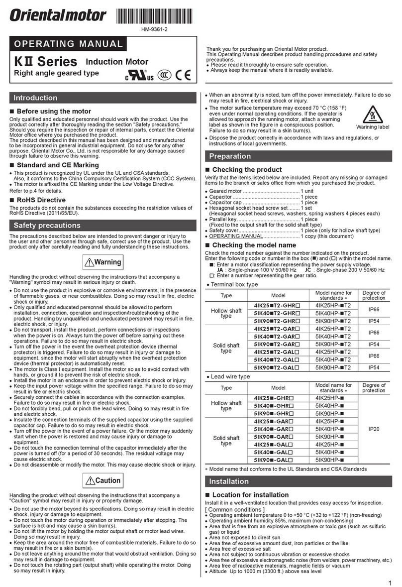
Warning label
To prevent the risk of electric shock, use the motor for class
Iequipment only.
Motore zur Verwendung in Geräten der Schutzklasse I.
Install the motor in an enclosure in order to prevent electric
shock or injury.
Install the motor so as to avoid contact with hands, or
ground it to prevent the risk of electric shock.
Die Gehäuse der Motore sind mit einer Schraube und
Zahnscheibe sicher mit dem geerdeten Gehäuse des Gerätes zu
verbinden.
Keep the input-power voltage within the specification to
avoid fire and electric shock.
Connect the cables securely according to the wiring
diagram in order to prevent fire and electric shock.
Do not forcibly bend, pull or pinch the lead wires. Doing so
may result in fire and electric shock.
Be sure to insulate the connection terminal of the capacitor.
Failure to do so may result in electric shock.
Turn off the power in the event of a power failure, or the
motor will suddenly start when the power is restored and
may cause injury or damage to equipment.
Do not touch the connection terminal of the capacitor
immediately after the power is turned off (for a period of
30 seconds). The residual voltage may cause electric
shock.
Do not disassemble or modify the motor. This may cause
electric shock or injury.
Do not use the motor beyond its specifications, or electric
shock, injury or damage to equipment may result.
Do not touch the motor during operation or immediately
after stopping. The surface is hot and may cause a skin
burn(s).
Do not hold the motor output shaft or motor lead wires. This
may cause injury.
Keep the area around the motor free of combustible
materials in order to prevent fire or a skin burn(s).
To prevent the risk of damage to equipment, leave nothing
around the motor that would obstruct ventilation.
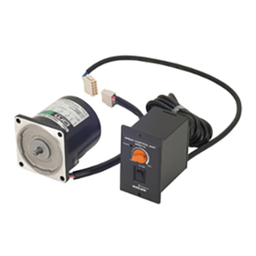
Use a motor and speed controller only in the specified
combination. An incorrect combination may cause a fire.
To prevent bodily injury, do not touch the rotating parts
(output shaft) of the motor during operation.
When an abnormality is noted, turn off the power
immediately, or fire, electric shock or injury may occur.
The motor’s surface temperature may
exceed 70 °C, even under normal operating
conditions. If a motor is accessible during
operation, post the warning label shown in
the figure in a conspicuous position to
prevent the risk of skin burn(s).
To dispose of the motor, disassemble it into parts and
components as much as possible and dispose of individual
parts/components as industrial waste.
Preparation
Checking the product
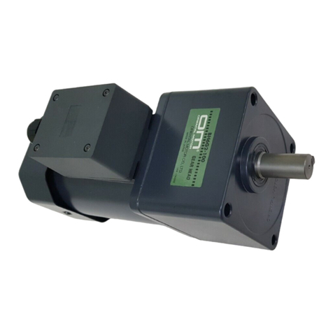
Verify that the items listed below are included. Report any
missing or damaged items to the branch or sales office from
which you purchased the product.
• Motor .............................1 unit
• Capacitor........................1 piece
• Capacitor cap .................1 piece
• Operating manual...........1 copy
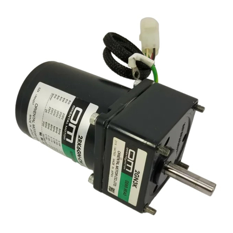
Checking the model name
Check the model number against the number indicated on the
product.
These motors can be driven by the speed controller as follows:
Single-phase 100 V/110 V/115 V: ES01
Single-phase 200 V/220 V/230 V: ES02
●Induction motors
Model Motor model Capacitor model
2IK6RGN-AW2J 2IK6RGN-AW2 CH35FAUL2
2IK6RGN-AW2U 2IK6RGN-AW2 CH25FAUL2
2IK6RGN-CW2J 2IK6RGN-CW2 CH08BFAUL
2IK6RGN-CW2E 2IK6RGN-CW2 CH06BFAUL
3IK15RGN-AW2J 3IK15RGN-AW2 CH55FAUL2
3IK15RGN-AW2U 3IK15RGN-AW2 CH45FAUL2
3IK15RGN-CW2J 3IK15RGN-CW2 CH15BFAUL
3IK15RGN-CW2E 3IK15RGN-CW2 CH10BFAUL
4IK25RGN-AW2J 4IK25RGN-AW2 CH80CFAUL2
4IK25RGN-AW2U 4IK25RGN-AW2 CH65CFAUL2
4IK25RGN-CW2J 4IK25RGN-CW2 CH20BFAUL
4IK25RGN-CW2E 4IK25RGN-CW2 CH15BFAUL
5IK40RGN-AW2J 5IK40RGN-AW2 CH110CFAUL2
5IK40RGN-AW2U 5IK40RGN-AW2 CH90CFAUL2
5IK40RGN-CW2J 5IK40RGN-CW2 CH30BFAUL
5IK40RGN-CW2E 5IK40RGN-CW2 CH23BFAUL
●Reversible motors
Model Motor model Capacitor model
2RK6RGN-AW2J 2RK6RGN-AW2 CH45FAUL2
2RK6RGN-AW2U 2RK6RGN-AW2 CH35FAUL2
2RK6RGN-CW2J 2RK6RGN-CW2 CH10BFAUL
2RK6RGN-CW2E 2RK6RGN-CW2 CH08BFAUL
3RK15RGN-AW2J 3RK15RGN-AW2 CH75CFAUL2
3RK15RGN-AW2U 3RK15RGN-AW2 CH60CFAUL2
3RK15RGN-CW2J 3RK15RGN-CW2 CH18BFAUL
3RK15RGN-CW2E 3RK15RGN-CW2 CH15BFAUL
4RK25RGN-AW2J 4RK25RGN-AW2 CH100CFAUL2
4RK25RGN-AW2U 4RK25RGN-AW2 CH80CFAUL2
4RK25RGN-CW2J 4RK25RGN-CW2 CH30BFAUL
4RK25RGN-CW2E 4RK25RGN-CW2 CH25BFAUL
5RK40RGN-AW2J 5RK40RGN-AW2 CH160CFAUL2
5RK40RGN-AW2U 5RK40RGN-AW2 CH120CFAUL2
5RK40RGN-CW2J 5RK40RGN-CW2 CH40BFAUL
5RK40RGN-CW2E 5RK40RGN-CW2 CH35BFAUL
The list above shows pinion shaft motors.
For the round shaft motor, “GN” in the model and motor model
are replaced by “A”.
Installation
Location for installation
The motor is designed and manufactured for installation in
equipment.
Install it in a well-ventilated location that provides easy access
for inspection. The location must also satisfy the following
conditions:
• Inside an enclosure that is installed indoors (provide vent
holes)
• Operating ambient temperature
−10 to +40 °C (+14 to +104 °F) (non-freezing)
−10 to +50 °C (+14 to +122 °F) for 100 V/200 V
• Operating ambient humidity 85%, maximum
(non-condensing)
