Oriental motor NETC01-CC User manual

HM-60089-2
Network converter
CC-Link compatible
NETC01-CC
USER MANUAL
Thank you for purchasing an Oriental Motor product.
This manual describes product handling procedures and safety precautions.
•Please read it thoroughly to ensure safe operation.
•Always keep the manual where it is readily available.

−2−
Table of contents
1 Safety precautions .................................... 3
2 Introduction ............................................... 5
3 Preparation................................................. 7
3.1 Checking the product.........................................7
3.2 Names and functions of parts..........................8
4 Installation................................................ 10
4.1 Location for installation .................................. 10
4.2 Installation method .......................................... 10
4.3 Installing and wiring in compliance with
EMC Directive ..................................................... 11
5 Connection ............................................... 13
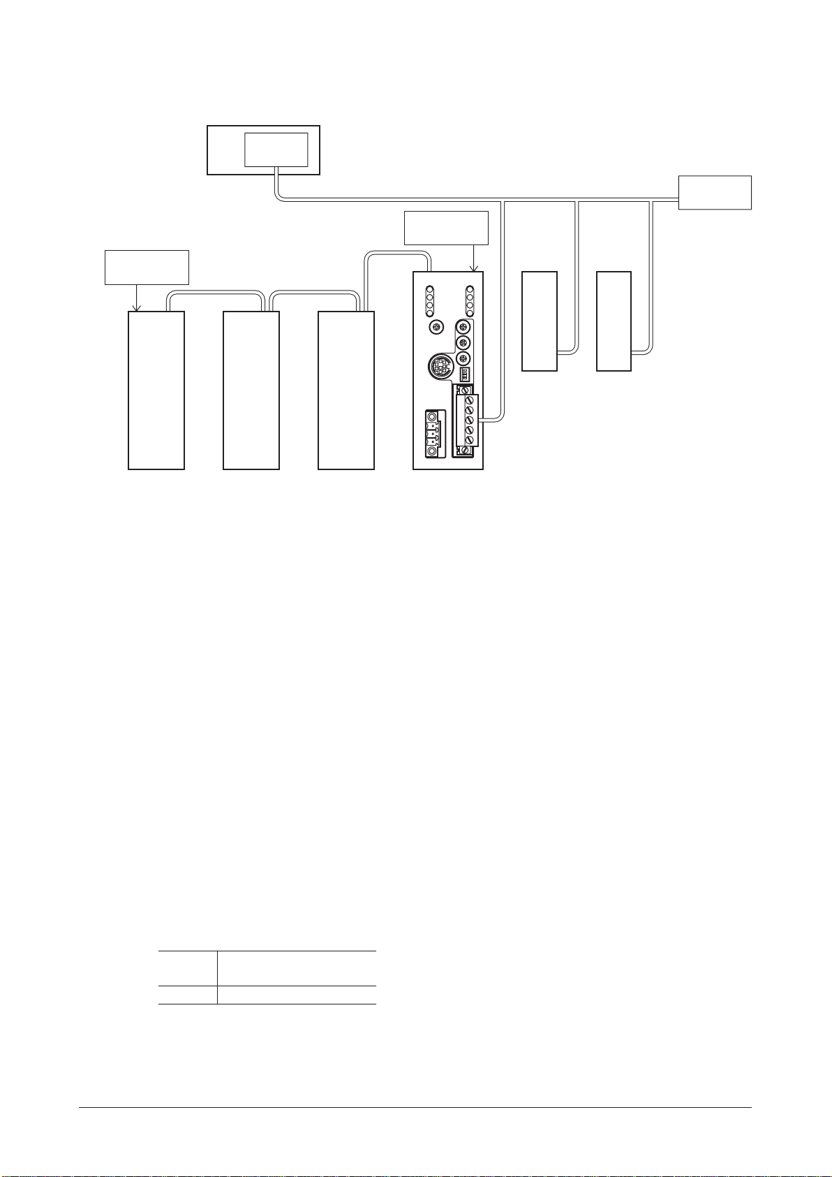
5.1 Connection example........................................ 13
5.2 Connecting the power supply and
grounding the NETC01-CC ....................... 13
5.3 Connecting the RS-485 communication
cable ...................................................................... 14
5.4 Connecting the CC-Link
communication ................................................. 15
5.5 Connecting the data setter............................ 15
6 Guidance ................................................... 16
7 Setting ....................................................... 19
7.1 Transmission rate of RS-485
communication ................................................. 19
7.2 Operation mode ................................................ 19
7.3 CC-Link station number.................................. 20
7.4 CC-Link baud rate.............................................. 20
7.5 Termination resistor.......................................... 20
8 Basic function........................................... 21
8.1 Remote I/O list.................................................... 21
8.2 Remote register list........................................... 22
8.3 Assignment of remote I/O.............................. 22
8.4 Details of remote I/O........................................ 23
8.5 Monitor ................................................................. 25
8.6 Command execution........................................ 26
8.7 Communication error code ...........................28
8.8 Read, write, save of parameters ................... 29
9 RS-485 communication specication.. 30
9.1 Operation mode ................................................ 30
9.2 RS-485 communication conguration....... 30
9.3 RS-485 communication and scan time...... 31
9.4 RS-485 communication status...................... 32
10 Troubleshooting and remedial
actions ....................................................... 33
10.1 Alarms.................................................................... 33
10.2 CC-Link communication error....................... 35
10.3 Warning................................................................. 36
10.4 When connecting with the RS-485
communication compatible product......... 36
11 Inspection ................................................. 37
12 General specications ............................ 38
13 Operation using the OPX-2A ............... 39
13.1 Overview of the OPX-2A............................... 39
13.2 Names and functions of parts....................... 40
13.3 Notation................................................................ 40
13.4 How to read the display.................................. 40
13.5 OPX-2A error display...................................... 41
13.6 Screen transitions.............................................. 42
13.7 Monitor mode..................................................... 44
13.8 Parameter mode ................................................ 45
13.9 Copy mode .......................................................... 45
14 Command code list .................................47
14.1 Application parameter .................................... 47
14.2 System parameter ............................................. 47
14.3 Maintenance command.................................. 48
14.4 Monitor command............................................ 48
15 Accessories (sold separately) ................ 49

Safety precautions
−3−
1 Safety precautions
The precautions described below are intended to prevent danger or injury to the user and other
personnel through safe, correct use of the product. Use the product only after carefully reading and fully
understanding these instructions.
Handling the product without observing the instructions that accompany a "Warning"
symbol may result in serious injury or death.
Handling the product without observing the instructions that accompany a "Caution"
symbol may result in injury or property damage.
The items under this heading contain important handling instructions that the user should
observe to ensure safe use of the product.
General
•Do not use the product in explosive or corrosive environments, in the presence of ammable gases,
locations subjected to splashing water, or near combustibles. Doing so may result in re or injury.
•Assign qualied personnel the task of installing, wiring, operating/controlling, inspecting and
troubleshooting the product. Failure to do so may result in re, injury or damage to equipment.
Connection
•Keep the power supply input voltage of the NETC01-CC within the specied range. Failure to do so may
result in re.
•For the power supply of the NETC01-CC, use a DC power supply with reinforced insulation on its
primary and secondary sides. Failure to do so may cause electric shock.
•Connect the cables securely according to the wiring diagram. Failure to do so may result in re.
•Do not forcibly bend, pull or pinch the cable. Doing so may cause re. Applying stress to the connection
area of the connectors may cause damage to the product.
Operation
•Turn off the NETC01-CC power in the event of a power failure. Or the motor may suddenly start when
the power is restored and may cause injury or damage to equipment.
•When an alarm of the NETC01-CC is generated, stop the motor. Failure to do so may result in re, injury
or damage to equipment.
Repair, disassembly and modication
•Do not disassemble or modify the NETC01-CC. Doing so may cause injury. Refer all such internal
inspections and repairs to the branch or sales ofce from which you purchased the product.

Safety precautions
−4−
General
•Do not use the NETC01-CC beyond its specications. Doing so may result in injury or damage to
equipment.
•Keep your ngers and objects out of the openings in the NETC01-CC. Failure to do so may result in re
or injury.
Installation
•Install the NETC01-CC in the enclosure in order to prevent injury.
•Keep the area around the NETC01-CC free of combustible materials in order to prevent re or a skin
burn(s).
•Do not leave anything around the NETC01-CC that would obstruct ventilation. Doing so may result in
damage to equipment.
Connection
•The power supply connector (CN1), CC-Link communication connector (CN2), data edit connector (CN3)
and RS-485 communication connector (CN6) of the NETC01-CC are not electrically insulated. When
grounding the positive terminal of the power supply, do not connect any equipment (PC, etc.) whose
negative terminal is grounded. Doing so may cause the NETC01-CC and these equipment to short,
damaging both.
Operation
•Use the NETC01-CC in combination with the designated applicable product. Failure to do so may result
in re.
•When operating the product, do so after making preparations that an emergency stop can be performed
at any time. Failure to do may result in injury.
•Set a suitable operation speed and acceleration/deceleration rate. Improper setting may cause loss of
the motor synchronism and moving the load to an unexpected direction, which may result in injury or
damage to equipment.
•Immediately when trouble has occurred, stop running and turn off the NETC01-CC power. Failure to do
so may result in re or injury.
•Static electricity may cause the NETC01-CC to malfunction or suffer damage. Do not touch the
NETC01-CC while the power is input. Always use an insulated screwdriver to adjust the switches of the
NETC01-CC.
Disposal
•To dispose of the NETC01-CC, disassemble it into parts and components as much as possible and
dispose of individual parts/components as industrial waste. Contact your nearest Oriental Motor ofce if
you have any questions.

Introduction
−5−
2 Introduction
Before use
Only qualied personnel should work with the product.
Use the product correctly after thoroughly reading the section "1 Safety precautions" on p.3.
The product described in this manual has been designed and manufactured for use in general industrial
equipment.
Do not use for any other purpose. For the power supply of the NETC01-CC, use a DC power supply with
reinforced insulation on its primary and secondary sides. Oriental Motor Co., Ltd. is not responsible for any
damage caused through failure to observe this warning.
Operating Manuals for the NETC01-CC
Operating manuals for the NETC01-CC are listed below.
After reading the following manuals, keep them in a convenient place so that you can reference them at
any time.
•Network converter CC-Link compatible NETC01-CC USER MANUAL
This manual explains the function, installation and connection of the NETC01-CC as well as operating
method.
For the command code or remote I/O of the RS-485 communication compatible product that can be
connected to the NETC01-CC, refer to the USER MANUAL of the corresponding RS-485 communication
compatible product.
•Network converter CC-Link communication NETC01-CC OPERATING MANUAL
This manual explains safety precautions, connector pin assignments and others.
•Data setting software MEXE02 OPERATING MANUAL
This manual explains the parameter setting method or monitor function using the MEXE02.
Overview of the product
The NETC01-CC is a communication converter between CC-Link and RS-485 communication.
By converting the CC-Link communication protocol of the upper level to the RS-485 communication
protocol of the lower level, Oriental Motor RS-485 communication compatible products can be operated via
CC-Link communication.
The RS-485 communication protocol of the lower level is Oriental Motor's own RS-485 communication
protocol.
The NETC01-CC is connected to CC-Link communication as the remote device station.
Also, using an accessory OPX-2A or MEXE02 (sold separately), the communication time can be monitored.

Introduction
−6−
System conguration
CC-Link master station
Termination
resistor *1
Termination
resistor ON *2
Termination
resistor ON *2
Termination
resistor
CC-Link communication
compatible product
NETC01-CCRS-485 communication
compatible product
RS-485 communication
*1 Termination resistor for CC-Link communication is not supplied. Use a termination resistor supplied with the
master station.
*2 The termination resistor for RS-485 communication is built into the product. For the NETC01-CC, whether to
enable or disable the termination resistor can be set using the termination resistor setting switch (SW3).
CE Marking
Because the input power supply voltage of this product is 24 VDC, it is not subject to the Low Voltage
Directive but install and connect this product as follows.
•This product is designed and manufactured to be installed within another device. Install the product in an
enclosure.
•For the power supply of the NETC01-CC, use a DC power supply with reinforced insulation on its
primary and secondary sides.
•Overvoltage category: Ⅰ
•Pollution degree: 2
•Degree of protection: IP20
•EMC Directive
This product has received EMC compliance under the conditions specied in “Example of NETC01-CC
installation and wiring” on p.12.
Since the conformity to the EMC Directive of the customer's equipment will be affected by various
conditions such as other control-system devices used together with the NETC01-CC, as well as
conguration of electrical components, wiring and installation condition, it therefore must be veried
through EMC measurements of the equipment by the customer.
Applicable standards
EMI EN 61000-6-4
EN 55011 group 1 class A
EMS EN 61000-6-2
Hazardous substances
The products do not contain the substances exceeding the restriction values of RoHS Directive (2011/65/
EU).

Preparation
−7−
3 Preparation
This chapter explains the items you should check, as well as the name and function of each part.
3.1 Checking the product
Verify that the items listed below are included. Report any missing or damaged items to the branch or sales
ofce from which you purchased the product.
•NETC01-CC.......................................................1 unit
•CN1 connector (3 pins) ......................................1 pc.
•CN2 connector (5 pins) ......................................1 pc.
•RS-485 communication cable ...........................2 pcs. [0.1 m (3.94 in.), 0.25 m (9.84 in.) each 1 pc.]
•OPERATING MANUAL.......................................1 copy
•USER MANUAL (CD-ROM) ...............................1 pc.

Preparation
−8−
3.2 Names and functions of parts
Termination resistor setting switch (SW3)
POWER LED (Green) L-RUN LED (Green)
SD LED (Green)
RD LED (Green)
Power supply connector (CN1)
C-ERR LED (Red)
C-DAT LED (Green)
ALARM LED (Red) L-ERR LED (Red)
Data edit connector (CN3)
RS-485 communication transmission
rate setting switch (SW1) CC-Link station number setting
switches (STATION No.×1, ×10)
Operation mode setting switch (SW2-No.1)
CC-Link baud rate setting switch (B-RATE)
CC-Link communication connector (CN2)
DIN lever
RS-485 communication
connector (CN6)

Preparation
−9−
Name Description Ref.
POWER LED (Green) This LED is lit while the power is input. −
ALARM LED (Red) This LED will blink when an alarm generates. It is possible to
check the generated alarm by counting the number of times
the LED blinks. p.33
C-DAT LED (Green) This LED is lit while transmitting and receiving data via RS-485
communication. −
C-ERR LED (Red) This LED is lit when an error has occurred via RS-485
communication. −
L-RUN LED (Green) This LED is lit while communicating properly via CC-Link
communication. p.35
L-ERR LED (Red) This LED is lit when an error has occurred via CC-Link
communication.
SD LED (Green) This LED is lit while transmitting data via CC-Link
communication. −
RD LED (Green) This LED is lit while receiving data via CC-Link communication. −
Power supply connector (CN1) Connects a 24 VDC power supply. p.13
CC-Link communication connector
(CN2) Connects the CC-Link communication cable. p.15
Data edit connector (CN3) Connects a PC in which the MEXE02 has been installed, or an
accessory OPX-2A (sold separately). p.15
RS-485 communication connector
(CN6) Connects the RS-485 communication cable. p.14
RS-485 communication transmission
rate setting switch (SW1) Sets the transmission rate of RS-485 communication. p.19
Operation mode setting switch
(SW2) Sets the operation mode. p.19
Termination resistor setting switch
(SW3) Sets whether to enable or disable termination resistor (120 Ω)
of RS-485 communication. p.20
CC-Link station number setting
switches (STATION No.×1, ×10)
Sets the CC-Link station number in the 01 to 64 range.
×10: Sets the tens place
×1: Sets the ones place p.20
CC-Link baud rate setting switch
(B-RATE) Sets the baud rate of CC-Link communication. p.20

Installation
−10−
4 Installation
This chapter explains the installation location and installation methods of the NETC01-CC.
The installation and wiring methods in compliance with the EMC Directive are also explained.
4.1 Location for installation
The NETC01-CC has been designed and manufactured for use as a component to be installed inside
equipment.
Install it in a well-ventilated location that provides easy access for inspection. The location must also satisfy
the following conditions:
•Inside an enclosure that is installed indoors (provide vent holes)
•Operating ambient temperature 0 to +40 °C (+32 to +104 °F) (non-freezing)
•Operating ambient humidity 85% or less (non-condensing)
•Area that is free of explosive atmosphere or toxic gas (such as sulfuric gas) or liquid
•Area not exposed to direct sun
•Area free of excessive amount of dust, iron particles or the like
•Area not subject to splashing water (rain, water droplets), oil (oil droplets) or other liquids
•Area free of excessive salt
•Area not subject to continuous vibration or excessive shocks
•Area free of excessive electromagnetic noise (from welders, power machinery, etc.)
•Area free of radioactive materials, magnetic elds or vacuum
4.2 Installation method
Install the NETC01-CC to a 35 mm (1.38 in.) width DIN rail.
There must be a clearance of at least 50 mm (1.97 in.) in the
horizontal and vertical directions, between the NETC01-CC
and enclosure or other equipment within the enclosure.
When installing two or more NETC01-CC in parallel, it is
possible to install them closely in the horizontal direction.
Provide a minimum clearance of 50 mm (1.97 in.) in the vertical
direction.
50 mm (1.97 in.)
or more
50 mm (1.97 in.)
or more
Note Be sure to install the NETC01-CC vertically (vertical
position). If the NETC01-CC is installed in the direction
other than vertical position, its heat radiation effect will
deteriorate.
Mounting to DIN rail
Pull down the DIN lever of the NETC01-CC and lock it. Hang the hook at the rear to the DIN rail, and push
in the NETC01-CC. After installation, secure the both sides of the NETC01-CC with the end plate.
Hook
DIN rail
DIN lever
End plate

Installation
−11−
Removing from DIN rail
Pull the DIN lever down until it locks using a at tip screwdriver, and lift the
bottom of the NETC01-CC to remove it from the rail.
Use force of about 10 to 20 N (2.2 to 4.5 lb.) to pull the DIN lever to lock it.
Excessive force may damage the DIN lever.
4.3 Installing and wiring in compliance with EMC Directive
Effective measures must be taken against the EMI that the NETC01-CC may give to adjacent control-
system equipment, as well as the EMS of the NETC01-CC itself, in order to prevent a serious functional
impediment in the machinery. The use of the following installation and wiring methods will enable the
NETC01-CC to be compliant with the EMC directive. Refer to “CE Marking” on p.6 for the applicable
standards.
Oriental Motor conducts EMC measurements on its NETC01-CC in accordance with “Example of
NETC01-CC installation and wiring” on p.12. The user is responsible for ensuring the machine’s compliance
with the EMC Directive, based on the installation and wiring explained below.
Power supply
This network converter is a product of DC power supply input.
Use a DC power supply (switching power supply etc.) that conforms to the EMC Directive.
Noise lter
•Connect a noise lter in the DC power supply input to prevent the noise generated in the NETC01-CC
from propagating externally through the power supply line.
•When using a power supply transformer, be sure to connect a noise lter to the AC input side of the
power supply transformer.
•For a noise lter, use HF2010A-UPF (SOSHIN ELECTRIC CO.,LTD), FN2070-10-06 (Schaffner EMC) or
equivalent product.
•Install the noise lter as close to the AC input terminal of DC power supply as possible. Use cable
clamps and other means to secure the AC input cables (AWG18: 0.75 mm2or more) and output cables
(AWG18: 0.75 mm2 or more) rmly to the surface of the enclosure.
•Connect the ground terminal of the noise lter to the grounding point, using as thick and short a wire as
possible.
•Do not place the AC input cable parallel with the noise lter output cable. Parallel placement will reduce
noise lter effectiveness if the enclosure's internal noise is directly coupled to the power supply cable by
means of stray capacitance.
How to ground
The cable used to ground the NETC01-CC and noise lter must be as thick and short as possible so
that no potential difference is generated. Choose a large, thick and uniformly conductive surface for the
grounding point.
Wiring the power supply cable and I/O signal cable
•Use a shielded cable of AWG22 (0.3 mm2) or more for the power supply cable of the NETC01-CC, and
keep it as short as possible.
•Use a supplied connector cable for the I/O signals cable of the NETC01-CC, and keep it as short as
possible.
•To ground the power supply cable and connector cable,
use a metal cable clamp or similar device that will maintain
contact with the entire circumference of the cable. Attach a
cable clamp as close to the end of the cable as possible, and
connect it as shown in the gure.
Cable cramp
Shielded cable

Installation
−12−
Notes about installation and wiring
•Connect the NETC01-CC and other peripheral control equipment directly to the grounding point so as to
prevent a potential difference from developing between grounds.
•When relays or electromagnetic switches are used together with the system, use noise lters and CR
circuits to suppress surges generated by them.
•Keep cables as short as possible without coiling and bundling extra lengths.
•Place the power cables such as the motor and power supply cables as far apart [100 to 200 mm (3.94 to
7.87 in.)] as possible from the signal cables. If the power cables and signal cables have to cross, cross
them at a right angle. Place the AC input cable and output cable of a noise lter separately from each
other.
Example of NETC01-CC installation and wiring
Master station
NETC01-CC
RS-485 communication cable
Power supply cable
(Shielded cable)
Grounded panel
OPX-2A
Noise
filter DC power
supply
AC
FG
FG
FG FG
FG
PEPE
Shielded caable
CC-Link
communication
cable
RS-485 communication
compatible product
Precautions about static electricity
Static electricity may cause the NETC01-CC to malfunction or suffer damage. While the NETC01-CC is
receiving power, handle the NETC01-CC with care and do not come near or touch the NETC01-CC.
Always use an insulated screwdriver to change the switches of the NETC01-CC.
Note The NETC01-CC uses parts that are sensitive to electrostatic charge. Before touching the
NETC01-CC, turn off the power to prevent electrostatic charge from generating. If an electrostatic
charge is impressed on the NETC01-CC, the NETC01-CC may be damaged.

Connection
−13−
5 Connection
This chapter explains the connection method of the NETC01-CC and power supply/communication cable,
as well as the grounding method.
5.1 Connection example
RS-485
communication cable
CC-Link
communication cable
24 VDC
GND
FG FG
Power supply connector (CN1)
CC-Link communication
connector (CN2)
RS-485 communication
connector (CN6)
Data edit connector (CN3)
OPX-2A MEXE02
Or
5.2 Connecting the power supply and grounding the NETC01-CC
Connecting the power supply
Connect the power supply cable (AWG22: 0.3 mm2) to the power supply connector (CN1) of the NETC01-
CC using the supplied CN1 connector (3 pins).
Grounding the NETC01-CC
Ground the Frame Ground terminal (FG) of the NETC01-CC as necessary.
Ground using a wire of AWG24 to 16 (0.2 to 1.25 mm2), and do not share the protective earth terminal with
a welder or any other power equipment.
CN1 connector pin assignments
Pin No. Signal name Description
24 VDC power supply
CN1 connector (supplied)
GND
FG Power supply
connector (CN1)
1 +24 VDC +24 VDC 0.2 A or more
2 GND Power supply GND
3 FG Frame Ground

Connection
−14−
Connecting method
1. Strip the insulation cover of the lead wire by 7 mm (0.28 in.)
7 mm (0.28 in.)
2. Insert each lead wire into the CN1 connector and tighten
the screw using a screwdriver (connector screw size: M2).
Tightening torque: 0.22 to 0.25 N·m (31 to 35 oz-in)
Lead wire
Screwdriver
CN1 connector
3. Insert the CN1 connector into power supply connector (CN1)
and tighten the screws using a screwdriver (connector
screw size: M2.5).
Tightening torque: 0.4 N·m (56 oz-in)
Power supply
connector (CN1)
Note •When connecting, pay attention to the polarity of the power supply. Reverse-polarity connection
may cause damage to the NETC01-CC.
•Do not wire the power supply cable of the NETC01-CC in the same cable duct with other power
lines. Doing so may cause malfunction due to noise.
5.3 Connecting the RS-485 communication cable
Connect the NETC01-CC and RS-485
communication compatible product using
the supplied RS-485 communication
cable.
Connect the RS-485 communication cable
to RS-485 communication connector
(CN6). Since RS-485 communication
cables of two lengths are supplied, use
either one of the two.
You can also use a commercial LAN cable
to link drivers.
NETC01-CC
RS-485 communication
compatible product
RS-485 communication
connector (CN6)
Termination resistor
setting switch (SW3)
CN6 connector pin assignments
Pin No. Signal name Description
•NETC01-CC internal circuit and termination resistor
1 N.C.
2 GND
3 TR+
4 N.C.
5 N.C.
6 TR
-
7 N.C.
8 N.C.
120 Ω
0 V*
SW3
* The GND line is used in common with CN1 (not
insulated)
1 N.C. Not used (Do not connect anything.)
2 GND GND
3 TR+ RS-485 communication signal (+)
4 N.C. Not used
5 N.C. Not used
6 TR−RS-485 communication signal (−)
7 N.C. Not used
8 N.C. Not used

Connection
−15−
5.4 Connecting the CC-Link communication
Connect the CC-Link communication cable to the CC-Link communication connector (CN2) of the
NETC01-CC using the supplied CN2 connector (5 pins).
CN2 connector pin assignments
Pin No. Signal
name Description CN2 connector (supplied)
CC-Link communication
connector (CN2)
CC-Link communication
cable
FG
1 DA Communication cable2 DB
3 DG
4 SLD Communication shielded cable
5 FG Frame Ground
5.5 Connecting the data setter
Connect the OPX-2A cable or communication
cable for the data setting software to the data
edit connector (CN3) on the NETC01-CC.Data edit connector (CN3)
OPX-2A cable or communication
cable for the data setting software
The power supply connector (CN1), CC-Link communication connector (CN2), data edit
connector (CN3) and RS-485 communication connector (CN6) of the NETC01-CC are
not electrically insulated. When grounding the positive terminal of the power supply, do
not connect any equipment (PC, etc.) whose negative terminal is grounded. Doing so
may cause the NETC01-CC and these equipment to short, damaging both.

Guidance
−16−
6 Guidance
If you are new to the NETC01-CC, read this section to understand the operating methods along with the
operation ow.
As an example, this chapter explains how to perform positioning operation for the "CRK Series FLEX
Built-in controller type [described as the CRD-KD in this manual]," using the NETC01-CC via CC-Link
communication.
Note •Before operating the motor, check the condition of the surrounding area to ensure safety.
•Refer to "8.6 Command execution" on p.26 for how to set parameters.
STEP 1 Set the transmission rate, station address and
address number.
Using the parameter
1. Set the "connection (address number 0) (1D80h)" parameter of the NETC01-CC to "1: Enable."
2. Execute the "batch NV memory write (3E85h)" of the NETC01-CC.
3. Cycle the NETC01-CC power.
Note
•“Connection” parameters will be enabled after the power is cycled.
•The "connection" parameters and "batch NV memory write" command can be executed using the
OPX-2A or MEXE02.
Using the switches
Setting condition
•CC-Link station number: 1
•RS-485 transmission rate: 625 kbps
•CC-Link baud rate: Same as the master station
•Address number of the CRD-KD: 0
Connection device:
Network converter
CRD-KD address
number: 0
×10: 0
×1: 1
NETC01-CCCRD-KD
SW4: OFF
SW1 to 3: ON
CC-Link baud rate:
Same as master station
CC-Link station
number: 1
RS-485 transmission
rate: 625 kbps
SW1: 7
SW1: 0

Guidance
−17−
STEP 2 Check the connection and termination resistor
Termination resistor
(110 Ω1/2 W) Programmable controller
or master device
RS-485 communication cable
CC-Link communication
cable
NETC01-CC Termination resistor
(110 Ω1/2 W)
Termination resistor (SW3): ONTermination resistor (SW3): ON
CRD-KD FGFGFG
STEP 3 Turn on the power and check the setting
Check that the LED condition has become as shown in the gures.
Green LitGreen Lit
OffOff
Green Lit
Off
Green Lit
Off
Green Lit
Off
Green Lit
Green Lit
•When C-ERR (red) of the CRD-KD or NETC01-CC is lit: Check the transmission rate or address number
of RS-485 communication.
•When L-ERR (red) of the NETC01-CC is lit: Check the type of the CC-Link communication error.

Guidance
−18−
STEP 4 Execute positioning operation via remote I/O of CC-Link
communication.
1. Set the "START input mode (1C00h)" parameter of the CRD-KD to "0: Remote I/O."
(Initial setting: Direct I/O)
2. Set the position (travel amount: 1001h) and operating speed (1101h) to the operation data No.1 of the
CRK-KD.
3. Set the "Data No. input mode (1C0Dh)" parameter of the CRD-KD to "0: Remote I/O."
(Initial setting: Direct I/O)
4. Set the "STOP contact conguration (1C03h)" parameter of the CRD-KD to "0: Normally open."
(Initial setting: Normally closed)
5. Select the data No.01 by turning the M0 of the address number 0 for remote I/O of CC-Link
communication to ON.
6. Execute positioning operation by turning the START of the CC-Link remote I/O address number 0 to
ON.
Note Data set via CC-Link communication is written to the driver's RAM, but data in the RAM will be
cleared once the control power is turned off. To save the data set via CC-Link communication to
the non-volatile memory, execute "batch NV memory write" of the maintenance command. For
details, refer to“8.8 Read, write, save of parameters”on p.29.
STEP 5 Were you able to operate the motor properly?
How did it go? Were you able to operate the motor properly? If the motor does not function, check the
following points:
•Is any alarm present in the NETC01-CC or CRD-KD?
•Are the address number, transmission rate and termination resistor set correctly?
•Are the "connection" parameters of the NETC01-CC set correctly?
•Is the C-ERR LED lit? (RS-485 communication error)
•Is the L-ERR LED lit? (CC-Link communication error)
•Is the operation data set correctly?
•Is the motor for the CRD-KD excited? Or is the excitation setting correct?
•Are the CRD-KD parameters set correctly?
•Is the STOP input of the CRD-KD I/O turned ON?
For more detailed settings and functions, refer to the following pages.

Setting
−19−
7 Setting
This chapter explains how to set the functions of the NETC01-CC.
Operation mode setting switch
(SW2-No.1)
CC-Link station number setting
switches (STATION No.×1, ×10)
CC-Link baud rate setting switch
(B-RATE)
Termination resistor
setting switch (SW3)
RS-485 communication
transmission rate setting
switch (SW1)
Note Be sure to turn off the NETC01-CC power before setting the switches. If the switches are set while
the power is still on, the new switch settings will not become effective until the NETC01-CC power
is cycled.
7.1 Transmission rate of RS-485 communication
Set the transmission rate using the transmission rate setting switch (SW1).
Factory setting 7 (625 kbps)
Note •For the SW1, always set to "7." If the switch is set to the dial of "8" or higher, the communication
switch setting error alarm will be generated when turning on the power. And do not set the
switch to the dial of "0" to "6" because they cannot be used. (An alarm will not be generated.)
•For the transmission rate of the RS-485 communication compatible product, set to 625 kbps.
7.2 Operation mode
Set the operation mode according to the maximum number of the RS-485 communication compatible
products connecting to a NETC01-CC.
Set the operation mode using the operation mode setting switch (SW2-No.1).
Cycle the power after switching the operation mode.
Factory setting OFF (6-axes connection mode)
SW2-No.1 Description
OFF 6-axes connection mode
Up to 6 pieces of the RS-485 communication compatible products can be connected.
The number of remote I/Os per RS-485 communication compatible product is 16 points.
ON 12-axes connection mode
Up to 12 pieces of the RS-485 communication compatible product can be connected.
The number of remote I/Os per RS-485 communication compatible product is 8 points.
Note The SW2-No.2 to No.4 is not used.

Setting
−20−
7.3 CC-Link station number
Set the station number of the NETC01-CC using the two CC-Link station number setting switches (STATION
No.×1 and ×10). When connecting two or more CC-Link compatible products, do not set duplicate station
numbers.
Set the tens place with the "STATION No.×10" switch and the ones place with the "STATION No.×1" switch.
Setting range 01 to 64 (00 and 65 or higher cannot be used.)
Factory setting 1 (×10: 0, ×1: 1)
7.4 CC-Link baud rate
Set the CC-Link baud rate using the CC-Link baudrate setting switch (B-RATE).
Factory setting 0 (156 kbps)
B-RATE Baud rate
0 156 kbps
1 625 kbps
2 2.5 Mbps
3 5 Mbps
4 10 Mbps
5 to 9 Not used.
7.5 Termination resistor
Set the termination resistor (120 Ω) of RS-485 communication using the termination resistor setting switch
(SW3).
Always set the switch to ON for the NETC01-CC.
Factory setting ON (Termination resistor enable)
Termination resistor
setting switch (SW3)
ON
OFF
•NETC01-CC internal circtui and termination resistor
1 N.C.
2 GND
3 TR+
4 N.C.
5 N.C.
6 TR
-
7 N.C.
8 N.C.
120 Ω
0 V*
SW3
* The GND line is used in common with CN1
(not insulated).
SW3 Termination resistor (120 Ω)
OFF Disable
ON Enable
Table of contents
Other Oriental motor Media Converter manuals

Oriental motor
Oriental motor NETC01-ECT User manual

Oriental motor
Oriental motor BLV510 User manual

Oriental motor
Oriental motor NETC01-CC User manual

Oriental motor
Oriental motor NETC01-M2 User manual

Oriental motor
Oriental motor NETC01-M3 User manual

Oriental motor
Oriental motor NETC01-ECT User manual

Oriental motor
Oriental motor NETC01-ECT User manual
Popular Media Converter manuals by other brands

Seneca
Seneca Z-4RTD2 installation manual

Siemens
Siemens SINAMICS V20 Inverter operating instructions

ANTAIRA
ANTAIRA IMP-C100 Series Quick installation guide

Nortek Security & Control
Nortek Security & Control Xantech XT-DIG-11 user manual

ZyCast
ZyCast digi-MOD HD-1603 User guide and installation manual

SMSL
SMSL SU-8S user manual