manuals.online logo
Brands
  1. Home
  2. •
  3. Brands
  4. •
  5. Oriental motor
  6. •
  7. Media Converter
  8. •
  9. Oriental motor NETC01-ECT User manual

Oriental motor NETC01-ECT User manual

1
Introduction
Before use
Only qualied personnel should work with the product. Use the product
correctly after thoroughly reading the section "Safety precautions."
The product described in this manual has been designed and manufactured
to be incorporated in general industrial equipment. Do not use for any other
purpose. Oriental Motor Co., Ltd. is not responsible for any damage caused
through failure to observe this warning.
Operating Manuals for the NETC01-ECT
Operating manuals for the NETC01-ECT are listed below.
After reading the following manuals, keep them in a convenient place so that
you can reference them at any time.
•Network converter EtherCAT compatible NETC01-ECT
OPERATING MANUAL (this document)
This manual explains safety precautions, connector pin assignments and
others.
•Network converter EtherCAT compatible NETC01-ECT
USER MANUAL
This manual explains the function, installation and connection of the
NETC01-ECT as well as operating method.
The USER MANUAL does not come with the product. For details, contact your
nearest Oriental Motor sales oce or download from Oriental Motor Website
Download Page.
For the command code or remote I/O of the RS-485 communication
compatible product that can be connected to the NETC01-ECT, refer to
the USER MANUAL of the corresponding RS-485 communication compatible
product or AZ Series Function Edition.
•Data setting software MEXE02 OPERATING MANUAL
This manual explains the parameter setting method and monitor function
using the MEXE02.
CE Marking
zLow Voltage Directives
Because the input power supply voltage of this product is 24 VDC, it is not
subject to the Low Voltage Directive but install and connect this product as
follows.
yThis product is designed and manufactured to be incorporated in
equipment. Be sure to install the product in an enclosure.
yFor the NETC01-ECT power supply, use a DC power supply with reinforced
insulation on its primary and secondary sides.
yOvervoltage category: I
yPollution degree: 2
yDegree of protection: IP10
HM-60082-3
OPERATING MANUAL Thank you for purchasing an Oriental Motor product. This Operating Manual
describes product handling procedures and safety precautions.
yPlease read it thoroughly to ensure safe operation.
yAlways keep the manual where it is readily available.
Network Converter EtherCAT Compatible
NETC01-ECT
zEMC Directive
This product has received EMC compliance under the conditions specied in
"Example of installation and wiring" on the USER MANUAL.
The conformance of your mechanical equipment with the EMC Directive will
vary depending on such factors as the conguration, wiring, and layout for
other control system devices and electrical parts used with the NETC01-
ECT. It therefore must be veried through conducting EMC measures in a
state where all parts including the NETC01-ECT have been installed in the
equipment.
Applicable Standards
EMI EN 55011 group 1 class A, EN 61000-6-4
EMS EN 61000-6-2
Hazardous substances
The products do not contain the substances exceeding the restriction values
of RoHS Directive (2011/65/EU).
Checking the product
Verify that the items listed below are included. Report any missing or
damaged items to the branch or sales oce from which you purchased the
product.
yNETC01-ECT ................................................................ 1 unit
yCN1 connector (3-pins)................................................ 1 pc.
yRS-485 communication cable
[0.1 m (3.94 in.), 0.25 m (9.84 in.) each 1 pc.]........ 2 pcs.
yOPERATING MANUAL (this document) .................. 1 copy
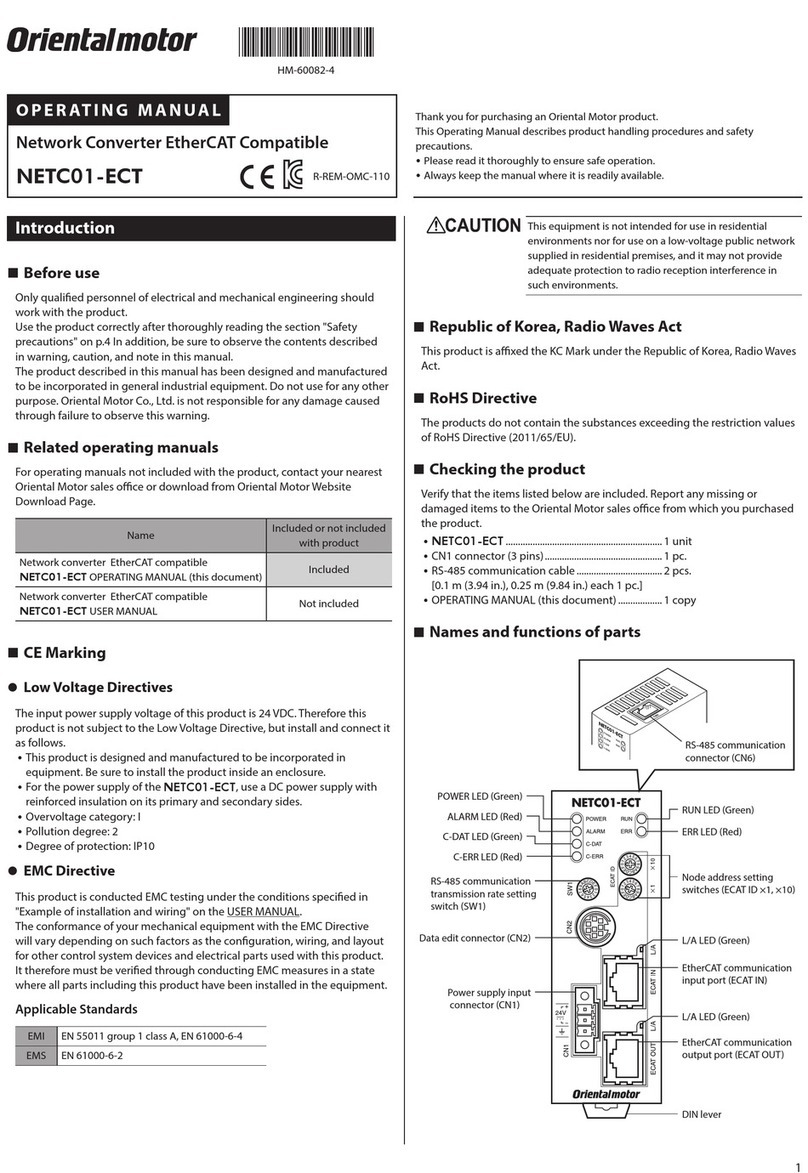
Names and functions of parts
zNETC01-ECT front face
POWER LED (Green)
RUN LED (Green)
L/A LED (Green)
Power supply input
connector (CN1)
C-ERR LED (Red)
C-DAT LED (Green)
ALARM LED (Red)
ERR LED (Red)
Data edit connec
tor (CN2)
RS-485 communication
transmission rate setting
switch (SW1)
EtherCAT communication
input port (ECAT IN)
L/A LED (Green)
EtherCAT communication
output port (ECAT OUT)
DIN lever
Node address setting
switches (ECAT
ID ×1, ×10)
2
Name Description
POWER LED (Green) This LED is lit while the power is input.
ALARM LED (Red)
This LED will blink when an alarm generates. It is
possible to check the generated alarm by counting the
number of times the LED blinks.
C-DAT LED (Green) This LED is lit while transmitting and receiving via RS-
485 communication.
C-ERR LED (Red) This LED is lit when an error has occurred via RS-485
communication.
RUN LED (Green)
ERR LED (Red)
L/A LED (Green)
These LEDs indicate the status of EtherCAT
communication. For detailed, refer to the following
pages.
Power supply input
connector (CN1) Connect 24 VDC power supply.
Data edit connector
(CN2)
Connects a PC in which the MEXE02 has been
installed, or an accessory OPX-2A.
EtherCAT communication
input port (ECAT IN)
This is a connector to perform EtherCAT
communication. Connect to the master controller.
EtherCAT communication
output port (ECAT OUT)
This is a connector to perform EtherCAT
communication. Connect to the following slave.
RS-485 communication
transmission rate setting
switch (SW1)
Set the transmission rate of RS-485 communication.
Factory setting: 7
Node address setting
switches
(ECAT ID ×1, ×10)
Set the node address of EtherCAT communication
within a range of 0 to 255 (00 to FF).
×10: Set the upper
×1: Set the lower
Factory setting: 1 (×10: 0, ×1: 1)
zNETC01-ECT top face
RS-485 communication connector (CN6)
Connect the RS-485 communication cable.
zLEDs to indicate the status of EtherCAT communication
LED indicator LED status *Description
RUN (Green)
OFF Initialization state
Blinking Pre-Operational state
Single ash Safe-Operational state
Lit Operational state (normal condition)
ERR (Red)
OFF No communication error
Blinking Communication setting error
Single ash Communication data error
Double ash Communication watchdog timeout
L/A (Green)
OFF No link
Lit Link establishment
Flickering Operation in progress after link
establishment
* Blinking Repetition of "ON (200 ms), OFF (200 ms)"
Single ash Repetition of "ON (200 ms), OFF (1,000 ms)"
Double ash Repetition of "ON (200 ms), OFF (200 ms), ON (200 ms),
OFF (1,000 ms)"
Flickering Repetition of "ON (50 ms), OFF (50 ms)"
Installation
Location for installation
The NETC01-ECT has been designed and manufactured to be incorporated
in equipment. Install it in a well-ventilated location that provides easy access
for inspection.
The location must also satisfy the following conditions:
yInside an enclosure that is installed indoors (provide vent holes)
yOperating ambient temperature 0 to +40 °C (+32 to +104 °F) (non-
freezing)
yOperating ambient humidity 85% or less (non-condensing)
yArea that is free of explosive atmosphere or toxic gas (such as sulfuric gas)
or liquid
yArea not exposed to direct sun
yArea free of excessive amount of dust, iron particles or the like
yArea not subject to splashing water (rain, water droplets), oil (oil droplets)
or other liquids
yArea free of excessive salt
yArea not subject to continuous vibration or excessive shocks
yArea free of excessive electromagnetic noise (from welders, power
machinery, etc.)
yArea free of radioactive materials, magnetic elds or vacuum
y1,000 m (3,300 ft.) or lower above sea level
Installation method
Mount the NETC01-ECT to a 35 mm (1.38 in.) width DIN rail.
There must be a clearance of at least 50 mm (1.97 in.) in the horizontal and
vertical directions, between the NETC01-ECT and enclosure or other
equipment within the enclosure.
When installing two or more NETC01-ECTs in parallel, it is possible to install
them closely in the horizontal direction.
Provide a minimum clearance of 50 mm (1.97 in.) in the vertical direction.
50 mm (1.97 in.) or mor
e
50 mm (1.97 in.) or mor
e
Be sure to install the NETC01-ECT in the vertical direction (vertical
position). If the NETC01-ECT is installed in the direction other than
vertical position, its heat radiation eect will deteriorate.
zMounting to DIN rail
Pull down the NETC01-ECT’s DIN lever and lock it. Hang the hook at the rear
to the DIN rail, and push in the NETC01-ECT. After installation, secure the
both sides of the NETC01-ECT with the end plate.
Hook
DIN rail
DIN lever
End plate
zRemoving from DIN rail
Pull the DIN lever down until it locks using a
at tip screwdriver, and lift the bottom of the
NETC01-ECT to remove it from the rail. Use
force of about 10 to 20 N (2.2 to 4.5 lb.) to pull
the DIN lever to lock it. Excessive force may
damage the DIN lever.
3
Pin assignment list
zCN1: Power supply input connector
Connect the power supply using the supplied CN1 connector (3-pins).
Pin No. Name Description
1+DC24 V +24 VDC 0.2 A or more
2 GND Power supply GND
3 FG Frame Ground
zCN6: RS-485 communication connector
Connect the RS-485 communication cable.
Since RS-485 communication cables of two lengths are supplied, use either
one of the two.
Pin No. Signal name Description
1 N.C. Not used (Do not connect anything.)
2 GND GND
3 TR+ RS-485 communication signal (+)
4 N.C. Not used
5 N.C. Not used
6 TR− RS-485 communication signal (−)
7 N.C. Not used
8 N.C. Not used
zECAT IN: EtherCAT communication input port
ECAT OUT: EtherCAT communication output port
Connect the EtherCAT communication cable.
Pin No. Signal name Description
1 TD+ output Transmitted data+ output
2 TD− output Transmitted data− output
3 RD+ input Received data+ input
4 N.C. Not used
5 N.C. Not used
6 RD− input Received data− input
7 N.C. Not used
8 N.C. Not used
Setting the switches
RS-485 communication
transmission rate setting
switch (SW1)
Node address setting
switches
(ECAT ID ×1, ×10)
Be sure to turn o the NETC01-ECT power before setting the
switches. If the switches are set while the power is still on, the new
switch settings will not become eective until the power is cycled.
RS-485 communication transmission rate
Set the RS-485 communication transmission rate setting switch (SW1) to 7.
Factory setting: 7 (625 kbps)
For the SW1, always set to 7. If the switch is set to the dial of 8 or more,
the communication switch setting error alarm will generate when
turning on the power. Also, do not set the switch to 0 to 6 because
these dials are unusable. (An alarm will not generate.)
Node Address (ECAT ID)
Set the node address of the NETC01-ECT using two node address setting
switches (ECAT ID ×1 and ECAT ID ×10) concurrently.
When connecting two or more EtherCAT-compatible products, set the node
address not to overlap.
Set the upper using the "ECAT ID ×10" and the lower using the "ECAT ID ×1."
Setting range : 0 to 255 (00 to FF)
Factory setting: 1 (×10: 0, ×1: 1)
Inspection
It is recommended that periodic inspections be conducted for the items listed
below. If an abnormal condition is noted, discontinue any use and contact
your nearest Oriental Motor sales oce.
zDuring inspection
yAre any of the NETC01-ECT DIN rail mounting parts loose?
yAre any of the NETC01-ECT connection loose?
yIs there attachment of dust, etc., on the NETC01-ECT?
yAre there any strange smells or appearances within the NETC01-ECT?
The NETC01-ECT uses semiconductor elements. Handle the
NETC01-ECT with care since static electricity may damage
semiconductor elements.
Troubleshooting and remedial actions
The NETC01-ECT provides alarms (protective functions). When an alarm
generates, the ALARM LED of the NETC01-ECT will blink. You can check the
generated alarm by counting the number of times the LED blinks.
zDescriptions of alarms
•No. of ALARM LED blinks: 7
Alarm
code Alarm type Cause Remedial action
83h Communication
switch setting error
RS-485
communication
transmission rate
setting switch
(SW1) was out-of-
specication.
Set the SW1 to 7.
84h
RS-485
communication
error
The RS-485
communication
error has been
detected three times
consecutively.
yCheck the transmission
rate of RS-485
communication.
yCheck the RS-485
communication
connector or cable.
86h
Check whether the
address number of the
RS-485 communication
compatible products has
duplicated.
•No. of ALARM LED blinks: 9
Alarm
code Alarm type Cause Remedial action
41h EEPROM error The stored data of the
NETC01-ECT was damaged.
Initialize the all
parameters.
•No. of ALARM LED blinks: Lit
Alarm
code Alarm type Cause Remedial action
F0h CPU error CPU malfunctioned. Cycle the power.
4
yUnauthorized reproduction or copying of all or part of this manual is
prohibited.
yOriental Motor shall not be liable whatsoever for any problems relating
to industrial property rights arising from use of any information, circuit,
equipment or device provided or referenced in this manual.
yCharacteristics, specications and dimensions are subject to change without
notice.
yWhile we make every eort to oer accurate information in the manual,
we welcome your input. Should you nd unclear descriptions, errors or
omissions, please contact the nearest oce.
yis a registered trademark or trademark of Oriental Motor
Co., Ltd., in Japan and other countries.
EtherCAT® is registered trademark and patented technology, licensed by Beckho
Automation GmbH, Germany.
© Copyright ORIENTAL MOTOR CO., LTD. 2012
Published in February 2018
T
echnical Support Tel:(800)468-3982
8:30
A.M. to 5:00 P.M., P.S.T. (M-F)
7:30
A.M. to 5:00 P.M., C.S.T. (M-F)
www
.orientalmotor.com
Schiessstraße 44, 40549 Düsseldor
f, Germany
T
echnical Support Tel:00 800/22 55 66 22
www
.orientalmotor.de
T
el:01256-347090
www
.oriental-motor.co.uk
T
el:01 47 86 97 50
www
.orientalmotor.fr
T
el:02-93906346
www
.orientalmotor.it
T
el:+55-11-3266-6018
www
.orientalmotor.com.br
• Please contact your nearest Oriental Motor oce for further information.
4-8-1Higashiueno
,Taito-ku,Tokyo 110-8536
Japan
T
el:03-6744-0361
www
.orientalmotor.co.jp
Tel:0800-060708
www.orientalmotor.com.tw
Singapore
Tel:1800-8420280
www.orientalmotor.com.sg
Tel:1800-806161
www.orientalmotor.com.my
Korea
Tel:080-777-2042
www.inaom.co.kr
Tel:1800-888-881
www.orientalmotor.co.th
Tel:400-820-6516
www.orientalmotor.com.cn
Tel:+91-80-41125586
www.orientalmotor.co.in
Hong Kong Branch
Tel:+852-2427-9800
zAlarm reset
Before resetting an alarm, always remove the cause of the alarm and ensure
safety, and then cycle the power.
Safety precautions
The precautions described below are intended to prevent danger or injury
to the user and other personnel through safe, correct use of the product.
Use the product only after carefully reading and fully understanding these
instructions.
Handling the product without observing the instructions that accompany a
"Warning" symbol may result in serious injury or death.
General
yDo not use the product in explosive or corrosive environments, in the
presence of ammable gases, locations subjected to splashing water, or
near combustibles. Doing so may result in re or injury.
yAssign qualied personnel the task of installing, wiring, operating/
controlling, inspecting and troubleshooting the product. Failure to do so
may result in re, injury or damage to equipment.
Connection
yKeep the input voltage of the NETC01-ECT within the specied range.
Failure to do so may result in re.
yFor the NETC01-ECT power supply, use a DC power supply with reinforced
insulation on its primary and secondary sides. Failure to do so may result in
electric shock.
yConnect the cables securely according to the wiring diagram. Failure to do
so may result in re.
yDo not forcibly bend, pull or pinch the power supply cable. Doing so may
cause re. Repetitive stress or overstress on the connection part may cause
damage to the product.
Operation
yIn the event of a power outage, turn o the power supply of the NETC01-
ECT. When the power is restored, the motor that is compatible with RS-
485 communication may suddenly operate and cause injury or damage to
equipment.
yWhen an alarm of the NETC01-ECT generates, stop the motor that is
compatible with RS-485 communication. Failure to do so may result in re,
injury or damage to equipment.
Repair, disassembly and modication
yDo not disassemble or modify the NETC01-ECT. Doing so may cause
injury. Refer all such internal inspections and repairs to the branch or sales
oce from which you purchased the product.
Handling the product without observing the instructions that accompany a
"Caution" symbol may result in injury or property damage.
General
yDo not use the NETC01-ECT beyond its specications. Doing so may
result in injury or damage to equipment.
yKeep your ngers and objects out of the openings in the
NETC01-ECT. Failure to do so may result in re or injury.
Installation
yInstall the NETC01-ECT in enclosures in order to prevent injury.
yKeep the area around the NETC01-ECT free of combustible materials in
order to prevent re or a skin burn(s).
yDo not leave anything around the NETC01-ECT that would obstruct
ventilation. Doing so may result in damage to equipment.
Operation
yUse the NETC01-ECT in combination with the designated compatible
products. Failure to do so may result in re.
yWhen operating the product, do so after making preparations that an
emergency stop can be performed at any time. Failure to do so may result
in injury.
ySet a suitable operation speed and acceleration/deceleration rate. Improper
setting may cause loss of the motor synchronism and moving the load to an
unexpected direction, which may result in injury or damage to equipment.
yImmediately when trouble has occurred, stop running and turn o the
NETC01-ECT power. Failure to do so may result in re or injury.
yStatic electricity may cause the NETC01-ECT to malfunction or suer
damage. While the NETC01-ECT is receiving power, do not touch the
NETC01-ECT. Always use an insulated screwdriver to adjust the NETC01-
ECT's switches.
Disposal
yTo dispose of the NETC01-ECT, disassemble it into parts and components
as much as possible and dispose of individual parts/components as
industrial waste. Contact your nearest Oriental Motor oce if you have any
questions.

Other Oriental motor Media Converter manuals

Oriental motor NETC01-M2 User manual

Oriental motor

Oriental motor NETC01-M2 User manual

Oriental motor NETC01-CC User manual

Oriental motor

Oriental motor NETC01-CC User manual

Oriental motor BLV510 User manual

Oriental motor

Oriental motor BLV510 User manual

Oriental motor NETC01-M3 User manual

Oriental motor

Oriental motor NETC01-M3 User manual

Oriental motor NETC01-ECT User manual

Oriental motor

Oriental motor NETC01-ECT User manual

Oriental motor NETC01-ECT User manual

Oriental motor

Oriental motor NETC01-ECT User manual

Oriental motor NETC01-CC User manual

Oriental motor

Oriental motor NETC01-CC User manual

Popular Media Converter manuals by other brands

Crystal Vision Dual DL-3G user manual

Crystal Vision

Crystal Vision Dual DL-3G user manual

Panduit Atlona OmniStream AT-OMNI-311 Solutions Setup and Configuration Guide

Panduit

Panduit Atlona OmniStream AT-OMNI-311 Solutions Setup and Configuration Guide

ION VCR 2 PC quick start guide

ION

ION VCR 2 PC quick start guide

Pandigital PANSCN05 user guide

Pandigital

Pandigital PANSCN05 user guide

Contemporary Research QMOD-HDMI RGB product manual

Contemporary Research

Contemporary Research QMOD-HDMI RGB product manual

TR-Electronic CMW582M-00002 Assembly instructions

TR-Electronic

TR-Electronic CMW582M-00002 Assembly instructions

Beijer Electronics BoX2 extreme installation manual

Beijer Electronics

Beijer Electronics BoX2 extreme installation manual

MiLAN MIL-185C installation guide

MiLAN

MiLAN MIL-185C installation guide

YATO YT-09910 Original instructions

YATO

YATO YT-09910 Original instructions

Motormate SP-2120AU instruction manual

Motormate

Motormate SP-2120AU instruction manual

Graviton LPD-1 user manual

Graviton

Graviton LPD-1 user manual

Siemens SINAMICS G120P operating instructions

Siemens

Siemens SINAMICS G120P operating instructions

Microchip Technology TC7129 General description

Microchip Technology

Microchip Technology TC7129 General description

WEISS DAC202 owner's manual

WEISS

WEISS DAC202 owner's manual

Anaheim Automation ENC-M9I Series Assembly instruction guide

Anaheim Automation

Anaheim Automation ENC-M9I Series Assembly instruction guide

X2E Automotive Ethernet Converter user manual

X2E

X2E Automotive Ethernet Converter user manual

Reach ENC110 user manual

Reach

Reach ENC110 user manual

Manhattan IADAP USB32-HDMIPD instructions

Manhattan

Manhattan IADAP USB32-HDMIPD instructions

manuals.online logo
manuals.online logoBrands
  • About & Mission
  • Contact us
  • Privacy Policy
  • Terms and Conditions

Copyright 2025 Manuals.Online. All Rights Reserved.