Oriental motor NETC01-M3 User manual

HM-60093-3
Network converter
MECHATROLINK-Ⅲcompatible
NETC01-M3
USER MANUAL
Thank you for purchasing an Oriental Motor product.
This manual describes product handling procedures and safety precautions.
•Please read it thoroughly to ensure safe operation.
•Always keep the manual where it is readily available.

−2−
Table of contents
1 Safety precautions .................................... 3
2 Introduction ............................................... 4
3 Preparation................................................. 6
3.1 Checking the product.........................................6
3.2 Names and functions of parts..........................6
4 Installation.................................................. 8
4.1 Location for installation .....................................8
4.2 Installation method .............................................8
4.3 Installing and wiring in compliance with
EMC Directive.........................................................9
5 Connection ............................................... 11
5.1 Connection example........................................ 11
5.2 Connecting the power supply and
grounding the NETC01-M3 ....................... 11
5.3 Connecting the RS-485 communication
cable....................................................................... 12
5.4 Connecting the MECHATROLINK-Ⅲ
communication cable...................................... 13
5.5 Connecting the data setter............................ 13
6 Guidance ................................................... 14
7 Setting ....................................................... 17
7.1 Transmission rate of
RS-485 communication................................... 17
7.2 Operation mode ................................................ 17
7.3 Station number .................................................. 18
8 MECHATROLINK-Ⅲcommunication
format ........................................................ 19
8.1 Data format.......................................................... 19
8.2 Phase...................................................................... 19
9 Details of command................................ 20
9.1 No operation command (NOP: 00h)........... 20
9.2 Read ID command (ID_RD: 03h)...................21
9.3 Setup device command (CONFIG: 04h)..... 23
9.4 Read alarm or warning command
(ALM_RD: 05h).................................................... 24
9.5 Clear alarm or warning command
(ALM_CLR: 06h) .................................................. 24
9.6 Establish connection command
(CONNECT: 0Eh) ................................................. 25
9.7 Release connection command
(DISCONNECT: 0Fh)........................................... 26
9.8 Data READ/WRITE_A command
(DATA_RWA: 20h)............................................... 27
9.9 Timing chart of the data READ/WRITE_A
command............................................................. 38
10 Troubleshooting and remedial
actions ....................................................... 45
10.1 Alarms and MECHATROLINK-Ⅲ
communication error....................................... 45
10.2 Warning................................................................. 48
11 Inspection ................................................. 49
12 General specications ............................ 50
13 Operation using the OPX-2A ............... 51
13.1 Overview of the OPX-2A............................... 51
13.2 Names and functions of parts....................... 52
13.3 Notation................................................................ 52
13.4 How to read the display.................................. 52
13.5 OPX-2A error display...................................... 53
13.6 Screen transitions.............................................. 54
13.7 Monitor mode..................................................... 56
13.8 Parameter mode ................................................ 57
13.9 Copy mode .......................................................... 58
14 Accessories (sold separately) ................ 60

Safety precautions
−3−
1 Safety precautions
The precautions described below are intended to prevent danger or injury to the user and other
personnel through safe, correct use of the product. Use the product only after carefully reading and fully
understanding these instructions.
Handling the product without observing the instructions that
accompany a "Warning" symbol may result in serious injury or
death.
General
•Do not use the product in explosive or corrosive
environments, in the presence of ammable gases, locations
subjected to splashing water, or near combustibles. Doing so
may result in re or injury.
•Assign qualied personnel the task of installing, wiring,
operating/controlling, inspecting and troubleshooting the
product. Failure to do so may result in re, injury or damage
to equipment.
Connection
•Keep the power supply input voltage of the NETC01-M3
within the specied range. Failure to do so may result in re.
•For the power supply of the NETC01-M3, use a DC
power supply with reinforced insulation on its primary and
secondary sides. Failure to do so may cause electric shock.
•Connect the cables securely according to the wiring diagram.
Failure to do so may result in re.
•Do not forcibly bend, pull or pinch the cable. Doing so may
cause re. Applying stress to the connection area of the
connectors may cause damage to the product.
Operation
•Turn off the NETC01-M3 power in the event of a power
failure. Or the motor may suddenly start when the power is
restored and may cause injury or damage to equipment.
•When an alarm of the NETC01-M3 is generated, stop the
motor. Failure to do so may result in re, injury or damage to
equipment.
Repair, disassembly and modication
•Do not disassemble or modify the NETC01-M3. Doing
so may cause injury. Refer all such internal inspections
and repairs to the branch or sales ofce from which you
purchased the product.
Handling the product without observing the instructions that
accompany a "Caution" symbol may result in injury or property
damage.
General
•Do not use the NETC01-M3 beyond its specications. Doing
so may result in injury or damage to equipment.
•Keep your ngers and objects out of the openings in the
NETC01-M3. Failure to do so may result in re or injury.
Installation
•Install the NETC01-M3 in the enclosure in order to prevent
injury.
•Keep the area around the NETC01-M3 free of combustible
materials in order to prevent re or a skin burn(s).
•Do not leave anything around the NETC01-M3 that would
obstruct ventilation. Doing so may result in damage to
equipment.
Connection
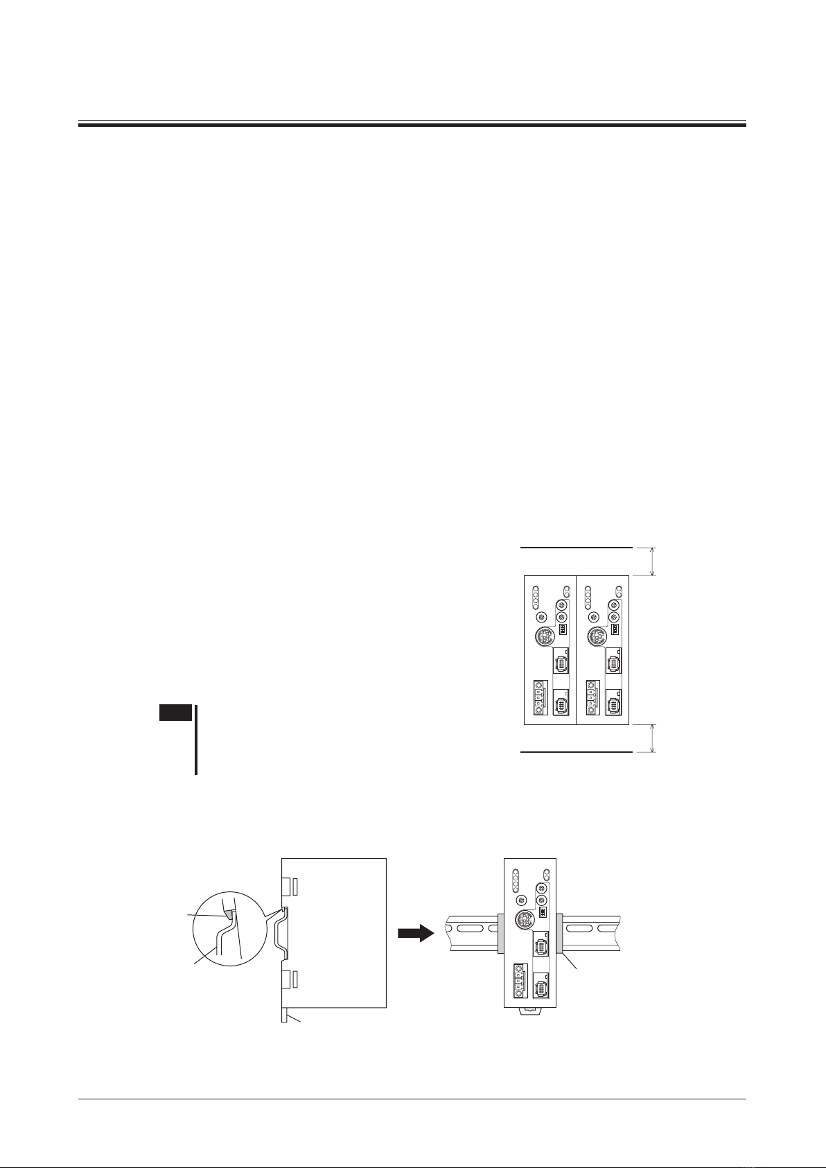
•The power supply connector (CN1), MECHATROLINK-Ⅲ
communication connector (CN2), data edit connector
(CN3) and RS-485 communication connector (CN6) of the
NETC01-M3 are not electrically insulated. When grounding
the positive terminal of the power supply, do not connect any
equipment (PC, etc.) whose negative terminal is grounded.
Doing so may cause the NETC01-M3 and these equipment
to short, damaging both.
Operation
•Use the NETC01-M3 in combination with the designated
applicable product. Failure to do so may result in re.
•When operating the product, do so after making preparations
that an emergency stop can be performed at any time.
Failure to do may result in injury.
•Set a suitable operation speed and acceleration/deceleration
rate. Improper setting may cause loss of the motor
synchronism and moving the load to an unexpected direction,
which may result in injury or damage to equipment.
•Immediately when trouble has occurred, stop running and
turn off the NETC01-M3 power. Failure to do so may result
in re or injury.
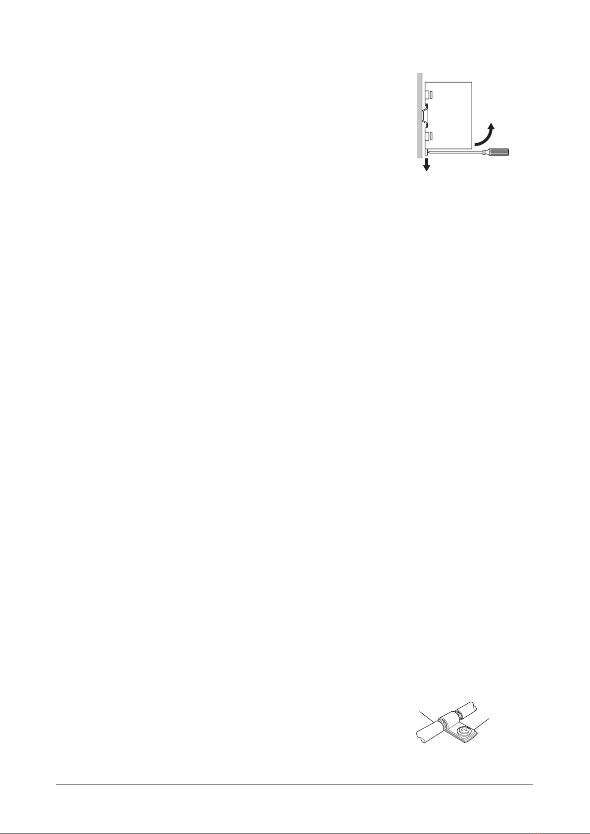
•Always use an insulated screwdriver to adjust the switches
of the NETC01-M3.
Disposal
•To dispose of the NETC01-M3, disassemble it into parts and
components as much as possible and dispose of individual
parts/components as industrial waste. Contact your nearest
Oriental Motor ofce if you have any questions.

Introduction
−4−
2 Introduction
Before use
Only qualied personnel should work with the product.
Use the product correctly after thoroughly reading the section "1 Safety precautions" on p.3.
The product described in this manual has been designed and manufactured for use in general industrial
equipment.
Do not use for any other purpose. For the power supply of the NETC01-M3, use a DC power supply with
reinforced insulation on its primary and secondary sides. Oriental Motor Co., Ltd. is not responsible for any
damage caused through failure to observe this warning.
Operating Manuals for the NETC01-M3
Operating manuals for the NETC01-M3 are listed below.
After reading the following manuals, keep them in a convenient place so that you can reference them at
any time.
•Network converter MECHATROLINK-Ⅲcompatible NETC01-M3 USER MANUAL
This manual explains the function, installation and connection of the NETC01-M3 as well as operating
method.
The USER MANUAL does not come with the product. For details, contact your nearest Oriental Motor
sales ofce or download from Oriental Motor Website Download Page.
For the command code or remote I/O of the RS-485 communication compatible product that can be
connected to the NETC01-M3, refer to the USER MANUAL of the corresponding RS-485 communication
compatible product or AZ Series Function Edition.
•Network converter MECHATROLINK-Ⅲcompatible NETC01-M3 OPERATING MANUAL
This manual explains safety precautions, connector pin assignments and others.
•Data setting software MEXE02 OPERATING MANUAL
This manual explains the parameter setting method or monitor function using the MEXE02.
Overview of the product
The NETC01-M3 is a communication converter between MECHATROLINK-Ⅲand RS-485 communication.
By converting the MECHATROLINK-Ⅲcommunication protocol of the upper level to the RS-485
communication protocol of the lower level, Oriental Motor RS-485 communication compatible products can
be operated via MECHATROLINK-Ⅲcommunication.
The RS-485 communication protocol of the lower level is Oriental Motor's own RS-485 communication
protocol.
Parameters of the NETC01-M3 cannot be set with the master station.
When setting the parameters of the NETC01-M3, use a MEXE02 or accessory OPX-2A.
When the MEXE02 is used, a communication cable for data setting software CC05IF-USB (accessory) is
needed to connect a PC and NETC01-M3. Be sure to purchase it.

Introduction
−5−
System conguration
RS-485 communication
Master station
MECHATROLINK-䊢
communication
MECHATROLINK-䊢
communication
compatible product
MECHATROLINK-䊢
communication
compatible product
NETC01-M3
Termination
resistor: ON *
RS-485
communication
compatible
products
RS-485
communication
compatible
products
RS-485
communication
compatible
products
* The termination resistor for RS-485 communication is built into the product.
CE Marking
Because the input power supply voltage of this product is 24 VDC, it is not subject to the Low Voltage
Directive but install and connect this product as follows.
•This product is designed and manufactured to be installed within another device. Install the product in an
enclosure.
•For the power supply of the NETC01-M3, use a DC power supply with reinforced insulation on its
primary and secondary sides.
•Overvoltage category:Ⅰ
•Pollution degree: 2
•Degree of protection: IP20
•EMC Directive
This product has received EMC compliance under the conditions specied in "Example of NETC01-M3
installation and wiring" on p.10.
The conformance of your mechanical equipment with the EMC Directive will vary depending on such
factors as the conguration, wiring, and layout for other control system devices and electrical parts used
with the NETC01-M3. It therefore must be veried through conducting EMC measures in a state where all
parts including the NETC01-M3 have been installed in the equipment.
Applicable standards
•EMI: EN 61000-6-4, EN 55011 group 1 class A
•EMS: EN 61000-6-2
Hazardous substances
The products do not contain the substances exceeding the restriction values of RoHS Directive (2011/65/
EU).

Preparation
−6−
3 Preparation
This chapter explains the items you should check, as well as the name and function of each part.
3.1 Checking the product
Verify that the items listed below are included. Report any missing or damaged items to the branch or sales
ofce from which you purchased the product.
•NETC01-M3......................................1 unit
•CN1 connector (3 pins) .....................1 pc.
•RS-485 communication cable ...........2 pcs. [0.1 m (3.94 in.), 0.25 m (9.84 in.) each 1 pc.]
•OPERATING MANUAL......................1 copy
3.2 Names and functions of parts
POWER LED (Green)
CONT LED (Green)
LINK1 LED (Green)
LINK2 LED (Green)
Power supply connector (CN1)
RS-485 communication transmission
rate setting switch (SW1)
C-ERR LED (Red)
C-DAT LED (Green)
ALARM LED (Red)
ERR LED (Red)
Data edit connector (CN3)
MECHATROLINK-䊢station number
setting switches (STATION No.×1, ×10)
Operation mode setting switch (SW2)
MECHATROLINK-䊢
communication connector (CN2-1)
MECHATROLINK-䊢
communication connector (CN2-2)
DIN lever
RS-485 communication
connector (CN6)

Preparation
−7−
Name Description Ref.
POWER LED (Green) This LED is lit while the power is input. −
ALARM LED (Red) This LED will blink or illuminate steadily when an alarm or
MECHATROLINK-Ⅲcommunication error has generated. p.45
C-DAT LED (Green) This LED is lit while transmitting and receiving data via RS-485
communication. −
C-ERR LED (Red) This LED is lit when an error has occurred via RS-485 communication. −
CONT LED (Green) This LED is lit while a connection is established. −
ERR LED (Red) This LED is lit when the MECHATROLINK-Ⅲcommunication error has
generated. p.45
RS-485 communication transmission
rate setting switch (SW1)
Sets the transmission rate of RS-485 communication.
Factory setting: 7 (625 kbps) p.17
Data edit connector (CN3) Connects a PC in which the MEXE02 has been installed, or an accessory
OPX-2A (sold separately). p.13
Power supply connector (CN1) Connects a 24 VDC power supply. p.11
MECHATROLINK-Ⅲstation address
setting switches (STATION No.×1, ×10)
Sets the station address in the 03h to EFh range.
Factory setting: 61h (×10=6, ×1=1)
×10: Sets the upper of the station address
×1: Sets the lower of the station address
p.18
Operation mode setting switch
(SW2-Nos.1 to 3)
Sets the operation mode.
•SW2-No.1: Sets the remote I/O occupied size.
Factory setting: OFF (16 bit mode)
•SW2-No.2, No.3: Sets the number of transmission bytes.
Factory setting: No.2=OFF, No.3=ON (32 bytes)
p.17
LINK1 LED (Green)
LINK2 LED (Green)
These LEDs are lit while MECHATROLINK-Ⅲcommunication is properly
connected. −
MECHATROLINK-Ⅲcommunication
connector (CN2-1, CN2-2) Connects the MECHATROLINK-Ⅲcommunication cable. p.13
RS-485 communication connector
(CN6) Connects the RS-485 communication cable. p.12

Installation
−8−
4 Installation
This chapter explains the installation location and installation methods of the NETC01-M3.
The installation and wiring methods in compliance with the EMC Directive are also explained.
4.1 Location for installation
The NETC01-M3 has been designed and manufactured for use as a component to be installed inside
equipment.
Install it in a well-ventilated location that provides easy access for inspection. The location must also satisfy
the following conditions:
•Inside an enclosure that is installed indoors (provide vent holes)
•Operating ambient temperature 0 to +40 °C (+32 to +104 °F) (non-freezing)
•Operating ambient humidity 85% or less (non-condensing)
•Area that is free of explosive atmosphere or toxic gas (such as sulfuric gas) or liquid
•Area not exposed to direct sun
•Area free of excessive amount of dust, iron particles or the like
•Area not subject to splashing water (rain, water droplets), oil (oil droplets) or other liquids
•Area free of excessive salt
•Area not subject to continuous vibration or excessive shocks
•Area free of excessive electromagnetic noise (from welders, power machinery, etc.)
•Area free of radioactive materials, magnetic elds or vacuum
4.2 Installation method
Install the NETC01-M3 to a 35 mm (1.38 in.) width DIN rail.
There must be a clearance of at least 50 mm (1.97 in.) in the
horizontal and vertical directions, between the NETC01-M3
and enclosure or other equipment within the enclosure.
When installing two or more NETC01-M3 in parallel, it is
possible to install them closely in the horizontal direction.
Provide a minimum clearance of 50 mm (1.97 in.) in the vertical
direction.
50 mm (1.97 in.)
or more
50 mm (1.97 in.)
or more
Note Be sure to install the NETC01-M3 vertically (vertical
position). If the NETC01-M3 is installed in the direction
other than vertical position, its heat radiation eect will
deteriorate.
Mounting to DIN rail
Pull down the DIN lever of the NETC01-M3 and lock it. Hang the hook at the rear to the DIN rail, and push
in the NETC01-M3. After installation, secure the both sides of the NETC01-M3 with the end plate.
Hook
DIN rail
DIN lever
End plate

Installation
−9−
Removing from DIN rail
Pull the DIN lever down until it locks using a at tip screwdriver, and lift
the bottom of the NETC01-M3 to remove it from the rail.
Use force of about 10 to 20 N (2.2 to 4.5 lb.) to pull the DIN lever to lock it.
Excessive force may damage the DIN lever.
4.3 Installing and wiring in compliance with EMC Directive
Effective measures must be taken against the EMI that the NETC01-M3 may give to adjacent control-
system equipment, as well as the EMS of the NETC01-M3 itself, in order to prevent a serious functional
impediment in the machinery. The use of the following installation and wiring methods will enable the
NETC01-M3 to be compliant with the EMC directive. Refer to "CE Marking" on p.5 for the applicable
standards.
Oriental Motor conducts EMC measurements on its NETC01-M3 in accordance with "Example of
NETC01-M3 installation and wiring" on p.10. The user is responsible for ensuring the machine’s compliance
with the EMC Directive, based on the installation and wiring explained below.
Power supply
This network converter is a product of DC power supply input.
Use a DC power supply (switching power supply etc.) that conforms to the EMC Directive.
Noise lter
•Connect a noise lter in the DC power supply input to prevent the noise generated in the NETC01-M3
from propagating externally through the power supply line.
•When using a power supply transformer, be sure to connect a noise lter to the AC input side of the
power supply transformer.
•For a noise lter, use HF2010A-UPF (SOSHIN ELECTRIC CO.,LTD), FN2070-10-06 (Schaffner EMC) or
equivalent product.
•Install the noise lter as close to the AC input terminal of DC power supply as possible. Use cable
clamps and other means to secure the AC input cables (AWG18: 0.75 mm2 or more) and output cables
(AWG18: 0.75 mm2 or more) rmly to the surface of the enclosure.
•Connect the ground terminal of the noise lter to the grounding point, using as thick and short a wire as
possible.
•Do not place the AC input cable parallel with the noise lter output cable. Parallel placement will reduce
noise lter effectiveness if the enclosure's internal noise is directly coupled to the power supply cable by
means of stray capacitance.
How to ground
The cable used to ground the NETC01-M3 and noise lter must be as thick and short as possible so
that no potential difference is generated. Choose a large, thick and uniformly conductive surface for the
grounding point.
Wiring the power supply cable and I/O signal cable
•Use a shielded cable of AWG22 (0.3 mm2) or more for the power supply cable of the NETC01-M3, and
keep it as short as possible.
•For the MECHATROLINK-Ⅲcommunication cable, use a dedicated connector cable.
•To ground the power supply cable , use a metal cable clamp
or similar device that will maintain contact with the entire
circumference of the cable. Attach a cable clamp as close to
the end of the cable as possible, and connect it as shown in
the gure.
Cable clamp
Shielded cable

Installation
−10−
Notes about installation and wiring
•Connect the NETC01-M3 and other peripheral control equipment directly to the grounding point so as to
prevent a potential difference from developing between grounds.
•When relays or electromagnetic switches are used together with the system, use noise lters and CR
circuits to suppress surges generated by them.
•Keep cables as short as possible without coiling and bundling extra lengths.
•Place the power cables such as the motor and power supply cables as far as 100 mm (3.94 in.) from the
signal cables. If the power cables and signal cables have to cross, cross them at a right angle. Place the
AC input cable and output cable of a noise lter separately from each other.
Example of NETC01-M3 installation and wiring
Master station
NETC01-M3
RS-485 communication cable
Power supply cable
(Shielded cable)
Grounded panel
OPX-2A
Noise
filter
DC power
supply
AC
FG
FG
FG
PEPE
Shielded cable
MECHATROLINK-䊢
communication cable
RS-485 communication
compatible product
Precautions about static electricity
Static electricity may cause the NETC01-M3 to malfunction or suffer damage. While the NETC01-M3 is
receiving power, handle the NETC01-M3 with care and do not come near or touch the NETC01-M3.
Always use an insulated screwdriver to change the switches of the NETC01-M3.
Note The NETC01-M3 uses parts that are sensitive to electrostatic charge. Before touching the NETC01-M3,
turn o the power to prevent electrostatic charge from generating. If an electrostatic charge is impressed
on the NETC01-M3, the NETC01-M3 may be damaged.

Connection
−11−
5 Connection
This chapter explains the connection method of the NETC01-M3 and power supply/communication cable,
as well as the grounding method.
5.1 Connection example
RS-485 communication cable
MECHATROLINK-䊢
communication cable
24 VDC
GND
FG
Power supply connector (CN1)
MECHATROLINK-䊢
communication connector (CN2-1)
RS-485 communication
connector (CN6)
Data edit connector (CN3)
OPX-2A
Use the OPX-2A or
MEXE02 to set parameters.
MEXE02
Or
Use the accessory communication
cable for the data setting software
when connecting the PC and
NETC01-M3.
5.2 Connecting the power supply and grounding the NETC01-M3
Connecting the power supply
Connect the power supply cable (AWG22: 0.3 mm2) to the power supply connector (CN1) of the
NETC01-M3 using the supplied CN1 connector (3 pins).
Grounding the NETC01-M3
Ground the Frame Ground terminal (FG) of the NETC01-M3 as necessary.
Ground using a wire of AWG24 to 16 (0.2 to 1.25 mm2), and do not share the protective earth terminal with
a welder or any other power equipment.
CN1 connector pin assignments
Pin No. Signal name Description
1 +24 VDC +24 VDC 0.2 A or more
2 GND Power supply GND
3FG Frame Ground
Note
•When connecting, pay attention to the polarity of the power supply. Reverse-polarity connection may
cause damage to the NETC01-M3.
•Do not wire the power supply cable of the NETC01-M3 in the same cable duct with other power
lines. Doing so may cause malfunction due to noise.

Connection
−12−
Connecting method
2. Insert each lead wire into the CN1
connector and tighten
the screw using a screwdriver.
Connector screw size: M2
Tightening torque: 0.22 to 0.25 N·m
(31 to 35 oz-in)
3. Insert the CN1 connector into the CN1 and
tighten the screws using a screwdriver.
Connector screw size: M2.5
Tightening torque: 0.4 N·m (56 oz-in)
7 mm
(0.28 in.)
1. Strip the insulation
cover of the lead wire
by 7 mm (0.28 in.)
Lead wire
CN1 connector
24 VDC
power supply
GND
FG
Power supply connector
(CN1)
5.3 Connecting the RS-485 communication cable
Connect the NETC01-M3 and RS-485 communication compatible product using the supplied RS-485
communication cable.
Connect the RS-485 communication cable to RS-485 communication connector (CN6). Since RS-485
communication cables of two lengths are supplied, use either one of the two.
You can also use a commercial LAN cable to link drivers.
RS-485 communication
connector (CN6)
RS-485 communication
compatible product NETC01-M3
CN6 connector pin assignments
Pin No. Signal name Description
•NETC01-M3 internal circuit and termination resistor
1 N.C.
2 GND
3 TR+
4 N.C.
5 N.C.
6 TR
-
7 N.C.
8 N.C.
120 Ω
0 V
∗
1 N.C. Not used (Do not connect anything.)
2 GND GND
3 TR+ RS-485 communication signal (+)
4N.C. Not used
5
6TR− RS-485 communication signal (−)
7N.C. Not used
8
* The GND line is used in common with CN1 (not insulated)

Connection
−13−
5.4 Connecting the MECHATROLINK-Ⅲcommunication cable
Connect the MECHATROLINK-Ⅲcommunication cable to
the MECHATROLINK-Ⅲcommunication connector (CN2-1
or CN2-2) of the NETC01-M3. For the MECHATROLINK-Ⅲ
communication cable, use a dedicated cable with connector.
Other MECHATRLINK-Ⅲcommunication compatible products
can be connected to the vacant connector.
MECHATROLINK-䊢
communication connector
(CN2-1)
MECHATROLINK-䊢
communication cable
5.5 Connecting the data setter
Connect the OPX-2A cable or communication cable for
the data setting software to the data edit connector (CN3)
on the NETC01-M3.Data edit connector (CN3)
OPX-2A cable or communication
cable for the data setting software
The power supply connector (CN1), MECHATROLINK-Ⅲcommunication connector (CN2-
1, CN2-2), data edit connector (CN3) and RS-485 communication connector (CN6) of
the NETC01-M3 are not electrically insulated. When grounding the positive terminal
of the power supply, do not connect any equipment (PC, etc.) whose negative terminal
is grounded. Doing so may cause the NETC01-M3 and these equipment to short,
damaging both.

Guidance
−14−
6 Guidance
If you are new to the NETC01-M3, read this section to understand the operating methods along with the
operation ow.
As an example, this chapter explains how to perform positioning operation for the "CRK Series
FLEX Built-in controller type [described as the CRD-KD in this manual]," using the NETC01-M3 via
MECHATROLINK-Ⅲcommunication.
Note
•Before operating the motor, check the condition of the surrounding area to ensure safety.
•Refer to "13.8 Parameter mode" on p.57 for how to set parameters.
STEP 1 Set the transmission rate, station address and address number
Using the parameter
1. Set the "connection (address number 0)" parameter of the NETC01-M3 to "1: Enable."
2. Cycle the NETC01-M3 power.
Note
•“Connection” parameters will be enabled after the power is cycled.
•When setting the parameters of the NETC01-M3, use the OPX-2A or MEXE02.
Using the switches
•Setting condition of CRD-KD
•Address number of CRD-KD: 0
•Connection device of CRD-KD: Network converter
•Setting condition of NETC01-M3
•MECHATROLINK-Ⅲstation address: 61h
•RS-485 transmission rate: 625 kbps
•Remote I/O occupied size: 16 bit mode
•Number of transmission bytes: 32 bytes
Connection device:
Network converter
CRD-KD address
number: 0
×10: 6
×1: 1
NETC01-M3CRD-KD
SW4: OFF
SW1 to 3: ON
MECHATROLINK-䊢
station number: 61h
SW2-No.1: OFF
Remote I/O occupied size:
16 bit mode
SW2-No.3: ON
SW2-No.2: OFF
Number of transmission
bytes: 32 bytes
SW1: 7
SW1: 0
RS-485 transmission
rate: 625 kbps

Guidance
−15−
STEP 2 Check the connection and set the termination resistor
Programmable controller
or master device
RS-485
communication cable
MECHATROLINK-
䊢
communication cable
NETC01-M3CRD-KD
FG
FG
Termination
resistor (SW3): ON
STEP 3 Turn on the power and check the setting
Check that the LED condition has become as shown in the gures.
Green Lit
Green Lit
Off
Off
Green Lit
Off
Green Lit
Off
Green Lit
Off
•When C-ERR (red) of the CRD-KD or NETC01-M3 is lit: Check the transmission rate or address number
of RS-485 communication.
•When ERR (red) of the NETC01-M3 is lit: Check the type of the MECHATROLINK-Ⅲcommunication
error.

Guidance
−16−
STEP 4 Set the parameters of CRD-KD
Set the parameters of the CRD-KD using any of the OPX-2A, MEXE02, RS-485 communication or
MECHATROLINK-Ⅲcommunication.
1. Set the "START input mode (1C00h)" parameter of the CRD-KD to "0: RS-485 communication."
(Initial setting: I/O)
2. Set the position (travel amount: 1001h) and operating speed (1101h) to the operation data No.1 of the
CRK-KD.
3. Set the "Data No. input mode (1C0Dh)" parameter of the CRD-KD to "0: RS-485 communication."
(Initial setting: I/O)
4. Set the "STOP contact conguration (1C03h)" parameter of the CRD-KD to "0: Normally open."
(Initial setting: Normally closed)
Note
•Operation data or parameters set via RS-485 communication or MECHATROLINK-Ⅲcommunication
will be written to the RAM of the CRD-KD. The data stored in the RAM will be erased when turning
o the power supply of the CRD-KD. When saving the data to the non-volatile memory, execute the
"batch NV memory write" command of the maintenance command.
•The operation data or parameters set by the OPX-2A or MEXE02 will be saved to the non-volatile
memory of the CRD-KD.
•The non-volatile memory can be rewritten approx. 100,000 times.
STEP 5 Execute positioning operation
Control the I/O signal of the CRD-KD using the standard I/O command (DATA_RWA: 20h) of
MECHATROLINK-Ⅲcommunication.
1. Select the data No.1 by turning the M0 of the address number 0.
2. Execute positioning operation by turning the START of the address number 0 to ON.
STEP 6 Were you able to operate the motor properly?
How did it go? Were you able to operate the motor properly? If the motor does not function, check the
following points:
•Is any alarm present in the NETC01-M3 or CRD-KD?
•Are the address number, transmission rate and termination resistor set correctly?
•Are the "connection" parameters of the NETC01-M3 set correctly?
•Is the C-ERR LED lit? (RS-485 communication error)
•Is the ERR LED lit? (MECHATROLINK-Ⅲcommunication error)
•Is the operation data set correctly?
•Is the motor for the CRD-KD excited? Or is the excitation setting correct?
•Are the CRD-KD parameters set correctly?
•Is the STOP input of the CRD-KD I/O turned ON?
For more detailed settings and functions, refer to the following pages.

Setting
−17−
7 Setting
This chapter explains how to set the functions of the NETC01-M3.
Operation mode setting switch
(SW2-Nos.1 to 3)
MECHATROLINK-䊢station
number setting switches
(STATION No.×1, ×10)
RS-485 communication
transmission rate setting
switch (SW1)
Note Be sure to turn o the NETC01-M3 power before setting the switches. If the switches are set while
the power is still on, the new switch settings will not become eective until the NETC01-M3 power is
cycled.
7.1 Transmission rate of RS-485 communication
Set the transmission rate using the transmission rate setting switch (SW1).
Factory setting 7 (625 kbps)
Note
•For the SW1, always set to "7." If the switch is set to the dial of "8" or higher, the communication switch
setting error alarm will be generated when turning on the power. And do not set the switch to the dial
of "0" to "6" because they cannot be used. (An alarm will not be generated.)
•For the transmission rate of the RS-485 communication compatible product, set to 625 kbps.
7.2 Operation mode
Set the remote I/O occupied size and number of transmission bytes for the RS-485 communication
compatible product connecting to a NETC01-M3. Set the remote I/O occupied size using the operation
mode setting switch SW2-No.1, and set the number of transmission bytes using the SW2-No.2 and No.3.
If the operation mode is changed, cycle the power.
Factory setting No.1: OFF (Remote I/O occupied size: 16 bit mode)
No.2: OFF, No.3: ON (Number of transmission bytes: 32 bytes)
SW2 Description Factory setting
No.1
Sets the remote I/O occupied size.
OFF: 16 bit mode (Up to 8 units can be connected)
ON: 8 bit mode (Up to 16 units can be connected)
OFF
No.2
No.3
Sets the number of transmission bytes.
No.2=OFF, No.3=OFF: 16 bytes
No.2=OFF, No.3=ON: 32 bytes
No.2=ON, No.3=OFF: 48 bytes
No.2=ON, No.3=ON: 64 bytes
No.2: OFF
No.3: ON
Note The SW2-No.4 is not used.

Setting
−18−
7.3 Station number
Set the station number using the two MECHATROLINK-Ⅲstation number setting switches (STATION
No.×1 and ×10). When connecting two or more MECHATROLINK-Ⅲcompatible products, do not set
duplicate station numbers.
Set the tens place with the "STATION No.×10" switch and the ones place with the "STATION No.×1"
switch.
Setting range 03h to EFh
Factory setting 61h (×10: 6, ×1: 1)
Note 00h to 02h and F0h to FFh cannot be used.

MECHATROLINK- Ⅲcommunication format
−19−
8 MECHATROLINK-Ⅲcommunication
format
This chapter explains the MECHATROLINK-Ⅲcommunication format that the NETC01-M3 supports.
8.1 Data format
The outline of the data format for MECHATROLINK-Ⅲcommunication is shown below. The NETC01-M3
is compatible with the cyclic communication mode.
The cyclic communication mode of MECHATROLINK-Ⅲcommunication species that the header elds are
0 byte to 3 bytes and the data elds are 4 bytes and later.
Byte Command
(Master to NETC01-M3)
Response
(NETC01-M3 to master)
Header eld
0 CMD RCMD
1WDT RWDT
2CMD_CTRL CMD_STAT
3
Data eld 4 to 31 Command data eld Response data eld
8.2 Phase
The communication phases of MECHATROLINK-Ⅲcommunication are classied as follows.
Phase Description
0This is a state at power-on. When turning on the power for the master station and slave station,
operation switches to the phase 1.
1This is a state waiting for the connection establishment between the master station and slave
station.
2Asynchronous communication between the master station and slave station is enabled. Only
asynchronous command can be used.
3Synchronous communication between the master station and slave station is enabled. Both
asynchronous command and synchronous command can be used.
4This is a state that the communication between the master station and slave station is stopped and
the connection is disconnected.
5This is a state turning off the power for the master station and slave station.

Details of command
−20−
9 Details of command
This chapter explains the common commands and standard I/O command that the NETC01-M3 supports.
Prole Command
code (Hex) Command Description Ref.
Common
command
00 NOP This command is used as "no operation command." p.20
03 ID_RD This command is used to read the product information as ID data. p.21
04 CONFIG This command is used to set up the NETC01-M3.p.23
05 ALM_RD
This command is used to read the alarm code, warning code or
MECHATROLINK-Ⅲcommunication error code that is currently
occurred.
p.24
06 ALM_CLR
This command is used to reset the alarm, warning or
MECHATROLINK-Ⅲcommunication error that is currently
occurred.
p.24
0E CONNECT This command is used to establish a connection of
MECHATROLINK-Ⅲcommunication. p.25
0F DISCONNECT This command is used to release a connection of
MECHATROLINK-Ⅲcommunication. p.26
Standard I/O
command 20 DATA_RWA
Operation commands to the RS-485 communication compatible
product, reading and writing parameters, and monitoring can be
executed via remote I/O or remote register.
p.27
9.1 No operation command (NOP: 00h)
This command is used as "no operation command." A response returns the present status.
Data format
Byte Command
(Master to NETC01-M3)
Response
(NETC01-M3 to master)
0NOP (00h) NOP (00h)
1WDT RWDT
2CMD_CTRL CMD_STAT
3
4 to 31 Reserved (0h) Reserved (0h)
Explanation of command
Device group Common command group
Communication type Asynchronous command
Completion of command
operation
•Conrms by the response RCMD=NOP (00h) and CMD_STAT.CMDRDY=1.
•When the CMD_STAT.D_ALM or CMD_STAT.D_WAR is equal to 1, use the ALM_
RD to read out the present alarm or warning codes and take appropriate action.
•When the CMD_STAT.CMD_ALM or CMD_STAT.COMM_ALM is other than 0, take
appropriate action according to the alarm code. Refer to "Command status (CMD_
STAT)" on p.37 for details.
Table of contents
Other Oriental motor Media Converter manuals

Oriental motor
Oriental motor NETC01-ECT User manual

Oriental motor
Oriental motor NETC01-ECT User manual

Oriental motor
Oriental motor BLV510 User manual

Oriental motor
Oriental motor NETC01-M2 User manual

Oriental motor
Oriental motor NETC01-ECT User manual

Oriental motor
Oriental motor NETC01-CC User manual

Oriental motor
Oriental motor NETC01-CC User manual